TIRE AND WHEEL TIRE PRESSURE WARNING SYSTEM C2174/74 Vehicle Speed Signal Malfunction C2191/91 Vehicle Speed Signal Error (Test Mode DTC)
DESCRIPTION
Speed signals are input into the tire pressure warning ECU and receiver from the combination meter sub-assembly. At the same time, the acceleration sensor in the tire pressure warning valve and transmitter detects driving conditions, and sends signals to the tire pressure warning ECU and receiver. If the speed signal from the combination meter sub-assembly stops and the acceleration sensor signal in the tire pressure warning valve and transmitter indicates that the vehicle is being driven, DTC C2174/74 is stored.
DTC C2191/91 is stored only during the test mode.
| DTC Code | Detection Condition | Trouble Area |
|---|---|---|
| C2174/74 | Vehicle speed signal malfunction | ·
Combination meter sub-assembly ·
Vehicle speed signal circuit ·
Wire harness or connector ·
Tire pressure warning ECU and receiver ·
Tire pressure warning valve and transmitter |
| C2191/91 | Test mode procedure is performed | ·
Combination meter sub-assembly ·
Vehicle speed signal circuit ·
Wire harness or connector ·
Tire pressure warning ECU and receiver ·
Tire pressure warning valve and transmitter |
WIRING DIAGRAM
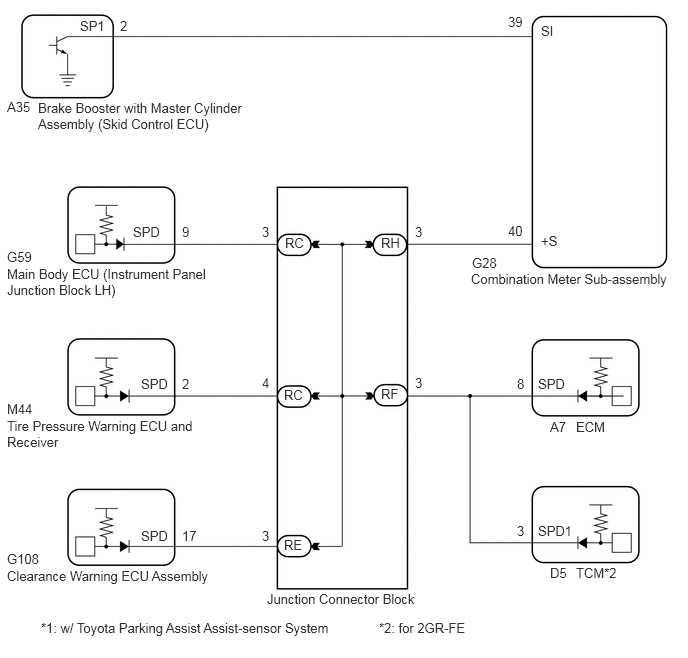
CAUTION / NOTICE / HINT
- NOTICE:
- ·
When replacing the tire pressure warning ECU and receiver, read the transmitter IDs stored in the old ECU using the GTS and write them down before removal.
·It is necessary to perform initialization (See page Drivetrain>TIRE AND WHEEL>TIRE PRESSURE WARNING SYSTEM>INITIALIZATION) after registration (See page Drivetrain>TIRE AND WHEEL>TIRE PRESSURE WARNING SYSTEM>REGISTRATION) of the transmitter IDs into the tire pressure warning ECU and receiver if the ECU and/or one of the valve and transmitters has been replaced.
- HINT:
-
When the speedometer is not moving, first troubleshoot the meter / gauge system (See page Vehicle Interior>METER / GAUGE / DISPLAY>METER / GAUGE SYSTEM>HOW TO PROCEED WITH TROUBLESHOOTING).
PROCEDURE
Turn the engine switch off.
Connect the GTS to the DLC3.
Turn the engine switch on (IG).
Turn the GTS on.
Enter the following menus: Chassis / Tire Pressure Monitor / Data List.
Check that the values indicated on the GTS and on the combination meter are the same.
| Tester Display | Measurement Item/Range | Normal Condition | Diagnostic Note |
|---|---|---|---|
| Vehicle Speed | Vehicle speed reading/
min.: 0 km/h (0 mph) max.: 255 km/h (158 mph) |
Actual vehicle speed | Speed indicated on the combination meter sub-assembly |
- OK:
Vehicle speed indicated on the GTS indicates the actual speed.
OK
NG
Perform a driving test.
Check for DTCs (See page Drivetrain>TIRE AND WHEEL>TIRE PRESSURE WARNING SYSTEM>DTC CHECK / CLEAR).
- HINT:
-
The time required for DTC C2174/74 to be stored is 20 minutes.
| Result | Proceed to |
|---|---|
| DTC C2174/74 is not output | A |
| DTC C2174/74 is output | B |
A
(See pageGeneral>INTRODUCTION>HOW TO TROUBLESHOOT ECU CONTROLLED SYSTEMS>HOW TO PROCEED WITH TROUBLESHOOTING)
B
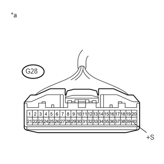
Disconnect the G28 combination meter sub-assembly connector.
Measure the voltage according to the value(s) in the table below.
- Standard Voltage:
Tester Connection Condition Specified Condition G28-40 (+S) - Body ground Engine switch on (IG) 4.5 to 14 V
| *a | Front view of wire harness connector
(to Combination Meter Sub-assembly) |
- HINT:
-
If any of the ECUs specified in the wiring diagram supplies power to the combination meter sub-assembly, the combination meter sub-assembly will output a waveform.
OK
NG
Reconnect the G28 combination meter sub-assembly connector.
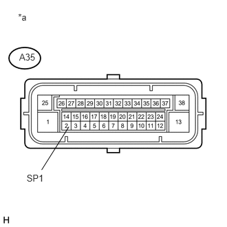
Disconnect the A35 brake actuator assembly (skid control ECU) connector.
Measure the voltage according to the value(s) in the table below.
- Standard Voltage:
Tester Connection Condition Specified Condition A35-2 (SP1) - Body ground Engine switch on (IG) 11 to 14 V
| *a | Front view of wire harness connector
(to Brake Actuator Assembly (Skid Control ECU)) |
OK
NG
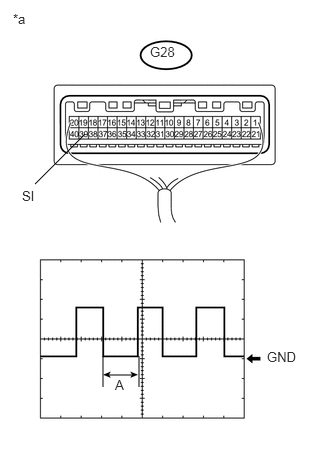
Check the input waveform.
Reconnect the A35 brake actuator assembly (skid control ECU) connector.
Remove the combination meter sub-assembly with the connector(s) still connected.
Connect an oscilloscope to terminal G28-39 (SI) and body ground.
Turn the engine switch on (IG).
Turn the wheel slowly.
Check the signal waveform according to the condition(s) in the table below.
| Item | Condition |
|---|---|
| Tool setting | 5 V/DIV., 20 ms./DIV. |
| Vehicle condition | Engine switch on (IG), wheel being rotated |
| *a | Component with harness connected
(Combination Meter Sub-assembly) |
- OK:
The waveform is similar to that shown in the illustration.
- HINT:
-
When the system is functioning normally, one wheel revolution generates 4 pulses. As the vehicle speed increases, the width indicated by (A) in the illustration narrows.
OK
NG
Disconnect the G28 combination meter sub-assembly connector.
Disconnect the A35 brake actuator assembly (skid control ECU) connector.
Measure the resistance according to the value(s) in the table below.
- Standard Resistance:
Tester Connection Condition Specified Condition G28-40 (SI) - A35-2 (SP1) Always Below 1 Ω G28-40 (SI) - Body ground Always 10 kΩ or higher
OK
NG
Disconnect the RH junction connector.
Measure the resistance according to the value(s) in the table below.
- Standard Resistance:
Tester Connection Condition Specified Condition G28-40 (+S) - RH-3 Always Below 1 Ω G28-40 (+S) - Body ground Always 10 kΩ or higher
OK
NG
Inspect for a short in the wire harness and connectors connected to the junction connector block shown in the wiring diagram.
- HINT:
-
If voltage is not present, it is possible that an ECU or circuit has a malfunction. The malfunctioning ECU or circuit will be diagnosed in the following steps.
Disconnect the RC, RE and RF connectors.
Measure the voltage according to the value(s) in the table below.
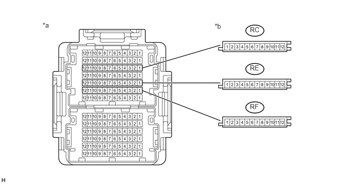
| *a | Component without harness connected
(Junction Connector Block) |
*b | Front view of wire harness connector
(to Junction Connector Block) |
- Standard Voltage:
Tester Connection Condition Specified Condition RC-3 - Body ground Engine switch on (IG) 4.5 to 14 V RC-4 - Body ground Engine switch on (IG) 4.5 to 14 V RE-3 - Body ground Engine switch on (IG) 4.5 to 14 V RF-3 - Body ground Engine switch on (IG) 4.5 to 14 V
- Result:
Result Proceed to Voltage is not present in one circuit. A Voltage is present in all of the circuits. B
A
B
Select the circuit for which voltage was not present in step 8.
- Result:
Tester Connection Proceed to RC-3 - Body ground A RC-4 - Body ground B RE-3 - Body ground*1 C RF-3 - Body ground*2 D RF-3 - Body ground*3 E
*1: w/ Toyota Parking Assist-sensor System
*2: for 2AZ-FE
*3: for 2GR-FE
A
B
C
D
E
Disconnect the G59 main body ECU (instrument panel junction block LH) connector.
Measure the resistance according to the value(s) in the table below.
- Standard Resistance:
Tester Connection Condition Specified Condition G59-9 (SPD) - Body ground Always 10 kΩ or higher
OK
NG
Disconnect the M44 tire pressure warning ECU and receiver connector.
Measure the resistance according to the value(s) in the table below.
- Standard Resistance:
Tester Connection Condition Specified Condition M44-2 (SPD) - Body ground Always 10 kΩ or higher
OK
NG
Disconnect the G108 clearance warning ECU assembly connector.
Measure the resistance according to the value(s) in the table below.
- Standard Resistance:
Tester Connection Condition Specified Condition G108-17 (SPD) - Body ground Always 10 kΩ or higher
OK
NG
Disconnect the A7 ECM connector.
Measure the resistance according to the value(s) in the table below.
- Standard Resistance:
Tester Connection Condition Specified Condition A7-8 (SPD) - Body ground Always 10 kΩ or higher
OK
NG
Disconnect the A7 ECM connector.
Disconnect the D5 TCM connector.
Measure the resistance according to the value(s) in the table below.
- Standard Resistance:
Tester Connection Condition Specified Condition RF-3 - Body ground Always 10 kΩ or higher
OK
NG
Reconnect the D5 TCM connector.
Measure the resistance according to the value(s) in the table below.
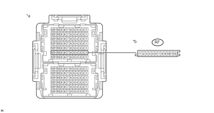
| *a | Component without harness connected
(Junction Connector Block) |
*b | Front view of wire harness connector
(to Junction Connector Block) |
- Standard Resistance:
Tester Connection Condition Specified Condition RF-3 - Body ground Engine switch on (IG) 4.5 to 14 V
- HINT:
-
If the result is as specified, there may be a short circuit in the ECM.
OK
NG
Replace the tire pressure warning ECU and receiver (See page Drivetrain>TIRE AND WHEEL>TIRE PRESSURE WARNING RECEIVER>REMOVAL).
NEXT
Perform registration (See page Drivetrain>TIRE AND WHEEL>TIRE PRESSURE WARNING SYSTEM>REGISTRATION).
NEXT
Perform registration (See page Drivetrain>TIRE AND WHEEL>TIRE PRESSURE WARNING SYSTEM>INITIALIZATION).
NEXT
Perform a driving test.
Check for DTCs (See page Drivetrain>TIRE AND WHEEL>TIRE PRESSURE WARNING SYSTEM>DTC CHECK / CLEAR).
- HINT:
-
The time required for DTC C2174/74 to be stored is 20 minutes.
- Result:
Result Proceed to DTC C2174/74 is output A DTC C2174/74 is not output B
A
B