Home › Power Source / Network › NETWORKING › CAN COMMUNICATION SYSTEM(for LHD with Entry and Start System) › 2015.06–2016.08
RM27T0E _57 Power Source / Network _053729 NETWORKING _0261031 CAN COMMUNICATION SYSTEM(for LHD with Entry and Start System) J

NETWORKING  CAN COMMUNICATION SYSTEM(for LHD with Entry and Start System)  Short to B+ in CAN Bus Line  


DESCRIPTION

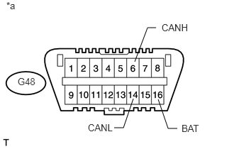
There may be a short circuit between the CAN bus lines and +B when the resistance between terminals 6 (CANH) and 16 (BAT) or terminals 14 (CANL) and 16 (BAT) of the DLC3 is below 6 kΩ.

Symptom Trouble Area
The resistance between terminals 6 (CANH) and 16 (BAT) or terminals 14 (CANL) and 16 (BAT) of the DLC3 is below 6 kΩ.
·

Short between CAN bus lines and +B

·

ECM

·

Brake actuator assembly (skid control ECU)*1

·

Master cylinder solenoid (skid control ECU)*2

·

Four wheel drive control ECU

·

Certification ECU (smart key ECU assembly)

·

Power management control ECU

·

Power steering ECU assembly

·

Navigation receiver assembly*3

·

Radio and display receiver assembly*4

·

Spiral cable sub-assembly (steering angle sensor)

·

Yaw rate sensor assembly

·

Center airbag sensor assembly

·

Main body ECU (multiplex network body ECU)

·

Combination meter assembly

·

No. 1 junction connector

·

No. 2 junction connector

·

No. 3 junction connector

·

No. 4 junction connector*1

·

No. 5 junction connector*2


*1: for 2TR-FE

*2: for 1GR-FE, 1KD-FTV, 1GD-FTV

*3: w/ Navigation System (for Navigation Receiver Type)

*4: w/ Navigation System (for Radio and Display Type) or w/o Navigation System


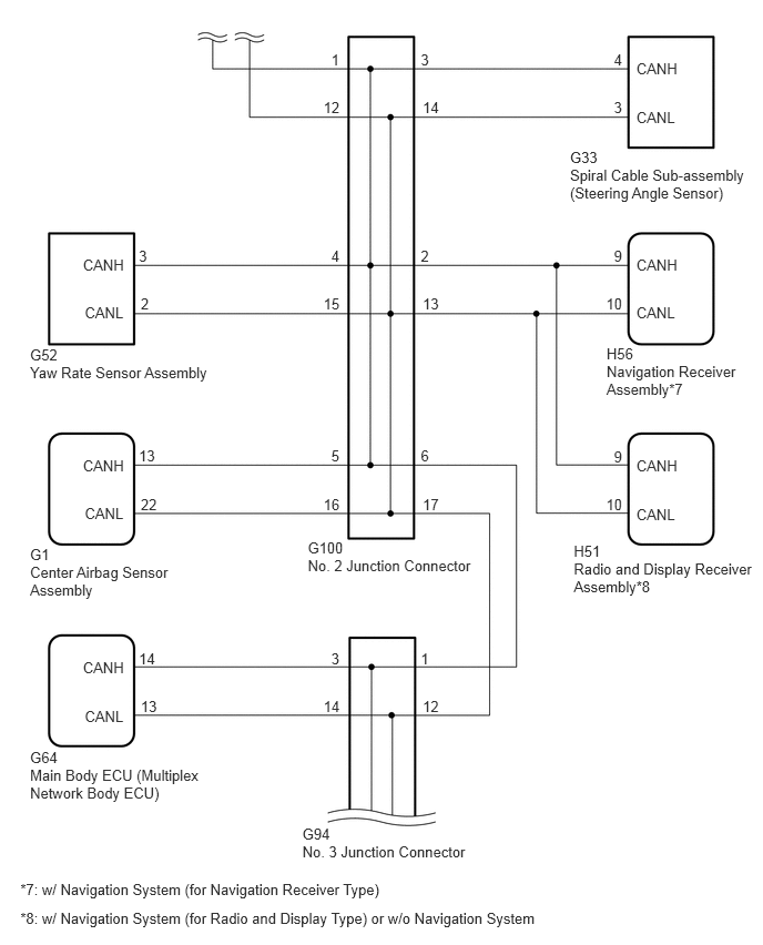
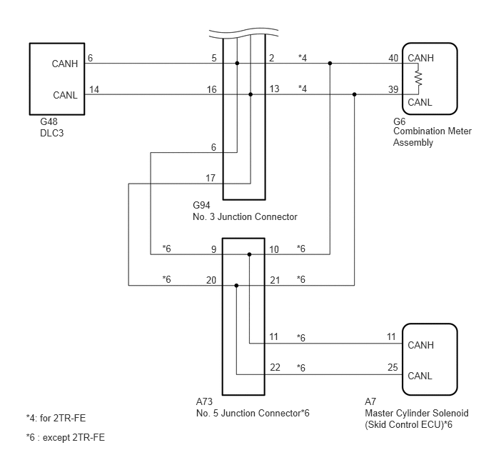
WIRING DIAGRAM
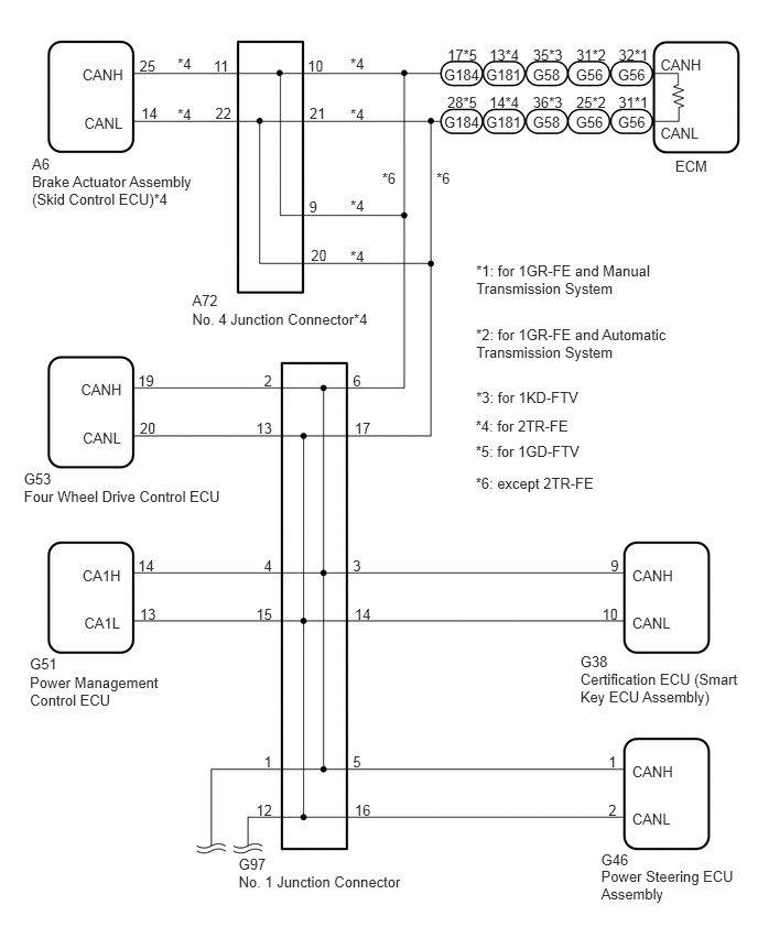
C334437E02
0.765,3.607 1.175,3.749 0.410,0.141 10 CANH 0.782,4.06 1.175,4.203 0.393,0.143 10 CANL 1.304,3.52 1.715,3.661 0.410,0.141 10 19 1.322,3.973 1.715,4.116 0.393,0.143 10 20 0.226,4.447 1.439,4.837 1.213,0.391 10 G53 0.226,4.615 2.181,4.969 1.955,0.354 10 Four Wheel Drive Control ECU 0.779,0.627 1.189,0.769 0.410,0.141 10 CANH 0.796,1.08 1.189,1.223 0.393,0.143 10 CANL 1.318,0.54 1.729,0.681 0.410,0.141 10 25 1.336,0.993 1.729,1.136 0.393,0.143 10 14 0.303,1.467 1.516,1.857 1.213,0.391 10 A6 0.303,1.635 1.897,1.989 1.594,0.354 10 Brake Actuator Assembly (Skid Control ECU)*4 0.779,5.363 1.189,5.504 0.410,0.141 10 CA1H 0.796,5.816 1.189,5.959 0.393,0.143 10 CA1L 1.304,5.275 1.715,5.417 0.410,0.141 10 14 1.322,5.728 1.715,5.871 0.393,0.143 10 13 0.282,6.202 1.495,6.593 1.213,0.391 10 G51 0.282,6.37 1.922,6.725 1.640,0.354 10 Power Management Control ECU 5.977,5.363 6.387,5.504 0.411,0.141 10 CANH 5.977,5.816 6.370,5.959 0.393,0.143 10 CANL 5.773,5.275 6.184,5.416 0.411,0.141 10 9 5.693,5.728 6.086,5.871 0.393,0.143 10 10 5.487,6.174 6.659,6.565 1.172,0.391 10 G38 5.487,6.342 7.072,6.697 1.585,0.354 10 Certification ECU (Smart Key ECU Assembly) 5.977,7.214 6.387,7.355 0.411,0.141 10 CANH 5.977,7.667 6.370,7.810 0.393,0.143 10 CANL 5.752,7.126 6.163,7.267 0.411,0.141 10 1 5.752,7.579 6.146,7.722 0.393,0.143 10 2 3.336,7.126 3.746,7.267 0.411,0.141 10 5 3.353,7.579 3.746,7.722 0.393,0.143 10 16 3.336,5.275 3.746,5.416 0.411,0.141 10 3 3.353,5.728 3.746,5.871 0.393,0.143 10 14 3.336,3.52 3.746,3.661 0.411,0.141 10 6 3.353,3.973 3.746,4.116 0.393,0.143 10 17 2.495,3.52 2.906,3.661 0.411,0.141 10 2 2.421,3.973 2.815,4.116 0.393,0.143 10 13 2.495,5.275 2.906,5.416 0.411,0.141 10 4 2.421,5.728 2.815,5.871 0.393,0.143 10 15 2.495,7.126 2.906,7.267 0.411,0.141 10 1 2.421,7.579 2.815,7.722 0.393,0.143 10 12 5.683,8.053 6.855,8.444 1.172,0.391 10 G46 5.683,8.207 6.983,8.512 1.300,0.305 10 Power Steering ECU Assembly 3.313,0.996 3.705,1.313 0.392,0.317 10 *4 3.313,0.52 3.705,0.837 0.392,0.317 10 *4 3.313,2.341 3.705,2.658 0.392,0.317 10 *4 3.313,1.865 3.705,2.182 0.392,0.317 10 *4 2.922,1.876 3.333,2.017 0.411,0.141 10 9 2.94,2.329 3.333,2.472 0.393,0.143 10 20 2.908,0.54 3.319,0.681 0.411,0.141 10 10 2.926,0.993 3.319,1.136 0.393,0.143 10 21 2.019,0.54 2.429,0.681 0.411,0.141 10 11 2.036,0.993 2.429,1.136 0.393,0.143 10 22 1.817,2.765 3.030,3.156 1.213,0.391 10 A72 1.817,2.934 3.794,3.178 1.977,0.244 10 No. 4 Junction Connector*4 2.256,8.09 3.469,8.480 1.213,0.391 10 G97 2.256,8.258 3.871,8.502 1.616,0.244 10 No. 1 Junction Connector 1.679,0.996 2.071,1.313 0.392,0.317 10 *4 1.679,0.52 2.071,0.837 0.392,0.317 10 *4 3.612,1.603 4.004,1.920 0.392,0.317 10 *6 4.126,1.603 4.518,1.920 0.392,0.317 10 *6 6.244,0.53 6.711,0.671 0.466,0.141 10 CANH 6.244,1.176 6.711,1.352 0.466,0.176 10 CANL 6.384,1.492 6.836,1.684 0.453,0.192 10 ECM 5.037,0.625 5.327,0.768 0.290,0.143 10 G58 5.037,1.078 5.327,1.221 0.290,0.143 10 G58 4.595,0.625 4.965,0.768 0.370,0.143 10 G181 4.595,1.078 4.965,1.221 0.370,0.143 10 G181 4.627,0.437 4.933,0.579 0.306,0.141 10 13*4 4.626,0.888 4.934,1.031 0.309,0.143 10 14*4 4.198,0.625 4.568,0.768 0.370,0.143 10 G184 4.198,1.078 4.568,1.221 0.370,0.143 10 G184 4.23,0.437 4.536,0.579 0.306,0.141 10 17*5 4.229,0.888 4.537,1.031 0.309,0.143 10 28*5 5.039,0.437 5.345,0.579 0.306,0.141 10 35*3 5.038,0.888 5.346,1.031 0.309,0.143 10 36*3 5.444,0.625 5.734,0.768 0.290,0.143 10 G56 5.444,1.078 5.734,1.221 0.290,0.143 10 G56 5.449,0.437 5.755,0.579 0.306,0.141 10 31*2 5.448,0.888 5.756,1.031 0.309,0.143 10 25*2 5.843,0.625 6.133,0.768 0.290,0.143 10 G56 5.843,1.078 6.133,1.221 0.290,0.143 10 G56 5.848,0.437 6.154,0.579 0.306,0.141 10 32*1 5.847,0.888 6.155,1.031 0.309,0.143 10 31*1 4.502,3.085 6.394,3.408 1.893,0.323 10 *2: for 1GR-FE and Automatic Transmission System 4.502,2.483 6.251,2.800 1.749,0.318 10 *1: for 1GR-FE and Manual Transmission System 4.502,3.674 6.444,3.816 1.942,0.142 10 *3: for 1KD-FTV 4.497,3.944 6.439,4.086 1.942,0.142 10 *4: for 2TR-FE 4.497,4.49 6.439,4.632 1.942,0.142 10 *6: except 2TR-FE 4.497,4.192 6.439,4.333 1.942,0.142 10 *5: for 1GD-FTV

C294468E03
5.977,2.406 6.387,2.547 0.411,0.141 10 CANH 5.766,2.318 6.177,2.459 0.411,0.141 10 9 5.693,2.771 6.086,2.914 0.393,0.143 10 10 5.977,2.859 6.370,3.002 0.393,0.143 10 CANL 5.697,3.239 6.869,3.629 1.172,0.391 10 H56 5.697,3.407 7.004,3.761 1.307,0.354 10 Navigation Receiver Assembly*7 5.977,4.292 6.387,4.433 0.411,0.141 10 CANH 5.766,4.204 6.177,4.345 0.411,0.141 10 9 5.693,4.657 6.086,4.800 0.393,0.143 10 10 5.977,4.745 6.370,4.888 0.393,0.143 10 CANL 5.389,5.097 6.561,5.487 1.172,0.391 10 H51 5.389,5.265 7.147,5.619 1.758,0.354 10 Radio and Display Receiver Assembly*8 3.952,2.318 4.363,2.459 0.411,0.141 10 2 3.97,2.771 4.363,2.914 0.393,0.143 10 13 3.111,0.478 3.522,0.619 0.411,0.141 10 1 3.038,0.931 3.431,1.074 0.393,0.143 10 12 0.282,3.413 2.209,3.767 1.927,0.354 10 Yaw Rate Sensor Assembly 0.779,2.405 1.189,2.547 0.410,0.141 10 CANH 0.796,2.858 1.189,3.001 0.393,0.143 10 CANL 1.304,2.318 1.715,2.459 0.410,0.141 10 3 1.322,2.771 1.715,2.914 0.393,0.143 10 2 0.282,3.245 1.495,3.635 1.213,0.391 10 G52 3.111,2.318 3.522,2.459 0.411,0.141 10 4 3.038,2.771 3.431,2.914 0.393,0.143 10 15 0.282,5.297 1.663,5.652 1.381,0.354 10 Center Airbag Sensor Assembly 0.779,4.29 1.189,4.431 0.410,0.141 10 CANH 0.796,4.743 1.189,4.886 0.393,0.143 10 CANL 1.304,4.202 1.715,4.344 0.410,0.141 10 13 1.322,4.655 1.715,4.798 0.393,0.143 10 22 0.282,5.129 1.495,5.520 1.213,0.391 10 G1 3.952,4.202 4.363,4.344 0.411,0.141 10 6 3.97,4.655 4.363,4.798 0.393,0.143 10 17 3.111,4.202 3.522,4.344 0.411,0.141 10 5 3.038,4.655 3.431,4.798 0.393,0.143 10 16 0.282,7.197 1.936,7.551 1.654,0.354 10 Main Body ECU (Multiplex Network Body ECU) 0.779,6.189 1.189,6.330 0.410,0.141 10 CANH 0.796,6.642 1.189,6.785 0.393,0.143 10 CANL 1.304,6.102 1.715,6.243 0.410,0.141 10 14 1.322,6.555 1.715,6.698 0.393,0.143 10 13 0.282,7.029 1.495,7.419 1.213,0.391 10 G64 3.952,6.102 4.363,6.243 0.411,0.141 10 1 3.97,6.555 4.363,6.698 0.393,0.143 10 12 3.111,6.102 3.522,6.243 0.411,0.141 10 3 3.038,6.555 3.431,6.698 0.393,0.143 10 14 2.84,7.745 4.052,8.136 1.213,0.391 10 G94 2.84,7.914 4.455,8.158 1.616,0.244 10 No. 3 Junction Connector 0.191,8.272 6.422,8.418 6.231,0.146 10 *7: w/ Navigation System (for Navigation Receiver Type) 0.191,8.545 6.108,8.691 5.917,0.146 10 *8: w/ Navigation System (for Radio and Display Type) or w/o Navigation System 5.977,0.565 6.387,0.706 0.411,0.141 10 CANH 5.977,1.018 6.370,1.161 0.393,0.143 10 CANL 5.766,0.478 6.177,0.619 0.411,0.141 10 4 5.766,0.931 6.160,1.074 0.393,0.143 10 3 3.952,0.478 4.363,0.619 0.411,0.141 10 3 3.97,0.931 4.363,1.074 0.393,0.143 10 14 5.354,1.393 6.526,1.784 1.172,0.391 10 G33 5.354,1.561 7.112,1.916 1.758,0.354 10 Spiral Cable Sub-assembly (Steering Angle Sensor) 2.891,5.061 4.104,5.452 1.213,0.391 10 G100 2.891,5.229 4.507,5.473 1.616,0.244 10 No. 2 Junction Connector

C294451E06
5.949,0.756 6.359,0.897 0.411,0.141 10 CANH 5.949,1.402 6.342,1.545 0.393,0.143 10 CANL 5.668,0.756 6.079,0.897 0.411,0.141 10 40 5.665,1.223 6.058,1.365 0.393,0.143 10 39 5.739,1.692 6.911,2.083 1.172,0.391 10 G6 5.739,1.828 6.935,2.182 1.196,0.354 10 Combination Meter Assembly 4.33,3.547 4.791,3.698 0.461,0.151 10 *6 4.33,3.988 4.791,4.139 0.461,0.151 10 *6 4.33,4.845 4.791,4.996 0.461,0.151 10 *6 4.33,5.286 4.791,5.437 0.461,0.151 10 *6 2.368,3.547 2.829,3.698 0.461,0.151 10 *6 2.368,3.988 2.829,4.139 0.461,0.151 10 *6 5.949,4.948 6.359,5.089 0.411,0.141 10 CANH 5.949,5.401 6.342,5.544 0.393,0.143 10 CANL 0.584,1.856 2.512,2.210 1.927,0.354 10 DLC3 0.754,0.848 1.165,0.990 0.410,0.141 10 CANH 0.772,1.301 1.165,1.444 0.393,0.143 10 CANL 1.28,0.761 1.690,0.902 0.410,0.141 10 6 1.297,1.214 1.690,1.357 0.393,0.143 10 14 0.584,1.688 1.797,2.078 1.213,0.391 10 G48 3.928,0.756 4.484,0.897 0.556,0.141 10 2 3.928,1.209 4.460,1.351 0.533,0.143 10 13 3.087,0.761 3.497,0.902 0.410,0.141 10 5 3.013,1.214 3.407,1.357 0.393,0.143 10 16 3.924,3.549 4.335,3.690 0.411,0.141 10 10 3.942,4.002 4.335,4.144 0.393,0.143 10 21 3.083,3.549 3.494,3.690 0.411,0.141 10 9 3.01,4.002 3.403,4.144 0.393,0.143 10 20 3.081,2.058 3.539,2.200 0.457,0.141 10 6 2.996,2.511 3.538,2.654 0.542,0.143 10 17 3.924,4.82 4.335,4.961 0.411,0.141 10 11 3.942,5.273 4.335,5.415 0.393,0.143 10 22 5.64,4.82 6.051,4.961 0.411,0.141 10 11 5.658,5.273 6.051,5.415 0.393,0.143 10 25 2.812,2.908 4.024,3.299 1.213,0.391 10 G94 2.812,3.076 4.427,3.320 1.616,0.244 10 No. 3 Junction Connector 5.326,5.769 6.498,6.159 1.172,0.391 10 A7 5.326,5.937 7.084,6.291 1.758,0.354 10 Master Cylinder Solenoid (Skid Control ECU)*6 2.863,5.768 4.076,6.158 1.213,0.391 10 A73 2.863,5.936 4.819,6.180 1.956,0.244 10 No. 5 Junction Connector*6 0.38,6.011 1.487,6.157 1.107,0.146 10 *4: for 2TR-FE 0.38,6.291 1.964,6.437 1.584,0.146 10 *6 : except 2TR-FE 4.352,0.756 4.908,0.897 0.556,0.141 10 *4 4.352,1.209 4.884,1.351 0.533,0.143 10 *4

CAUTION / NOTICE / HINT

HINT:

Operating the engine switch, any switches or any doors triggers related ECU and sensor communication with the CAN, which causes resistance variation.


PROCEDURE

1.DISCONNECT CABLE FROM NEGATIVE BATTERY TERMINAL
a.

Disconnect the cable from the negative (-) battery terminal before measuring the resistances of the CAN main wire and the CAN branch wire.

CAUTION:

Wait at least 90 seconds after disconnecting the cable from the negative (-) battery terminal to disable the airbag system.


NOTICE:
·

After turning the engine switch off, waiting time may be required before disconnecting the cable from the battery terminal. Therefore, make sure to read the disconnecting the cable from the battery terminal notice before proceeding with work (See page General>INTRODUCTION>REPAIR INSTRUCTION>PRECAUTION).

·

When disconnecting the cable, some systems need to be initialized after the cable is reconnected (See page General>INTRODUCTION>REPAIR INSTRUCTION>INITIALIZATION).


NEXT
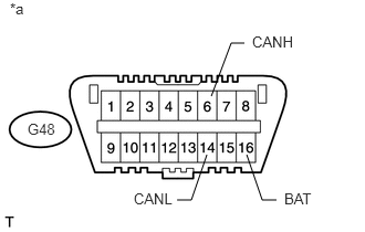
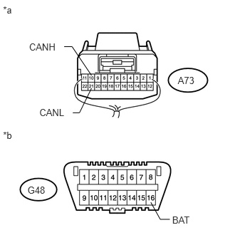
2.CHECK FOR SHORT TO B+ IN CAN BUS WIRE (DLC3 CAN BRANCH WIRE)
a.
U148271E06
1.99,0.906 2.177,0.406 2.177,0.406 2.302,0.406 false 1.948,1.458 1.802,1.885 1.802,1.885 1.667,1.885 false 2.323,1.458 2.469,1.885 2.469,1.885 2.604,1.885 false 0.094,0 0.26,0.188 0.167,0.188 10 false *a 2.375,0.313 2.844,0.5 0.469,0.188 10 false CANH 1.26,1.792 1.667,1.979 0.406,0.188 10 false CANL 0.26,1.135 0.552,1.323 0.292,0.188 10 false G48 2.677,1.792 2.99,1.948 0.313,0.156 10 false BAT

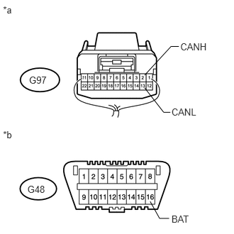
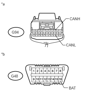
Disconnect the G94 No. 3 junction connector.


b.

Measure the resistance according to the value(s) in the table below.

Standard Resistance:
Tester Connection Switch Condition Specified Condition
G48-6 (CANH) - G48-16 (BAT) Engine switch off 6 kΩ or higher
G48-14 (CANL) - G48-16 (BAT) Engine switch off 6 kΩ or higher


Text in Illustration
*a Front view of DLC3


OK

3.CONNECT CONNECTOR

NG

REPAIR OR REPLACE CAN BRANCH WIRE CONNECTED TO DLC3 (CANH, CANL)

3.CONNECT CONNECTOR
a.

Reconnect the G94 No. 3 junction connector.


NEXT
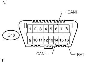
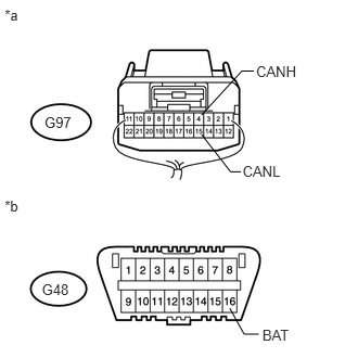
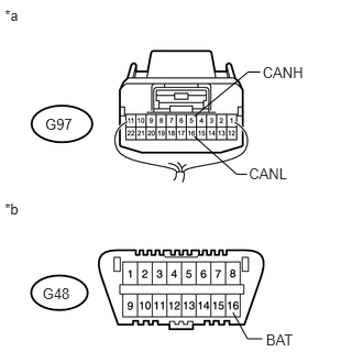
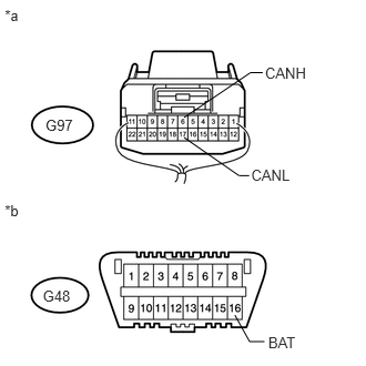
4.CHECK FOR SHORT TO B+ IN CAN BUS WIRE (NO. 1 JUNCTION CONNECTOR SIDE)
a.
U148271E07
1.969,0.917 2.156,0.417 2.156,0.417 2.281,0.417 false 1.958,1.448 1.813,1.875 1.813,1.875 1.677,1.875 false 2.323,1.469 2.469,1.896 2.469,1.896 2.604,1.896 false 0.094,0 0.26,0.188 0.167,0.188 10 false *a 2.344,0.333 2.813,0.521 0.469,0.188 10 false CANH 1.26,1.781 1.667,1.969 0.406,0.188 10 false CANL 0.26,1.135 0.552,1.323 0.292,0.188 10 false G48 2.677,1.813 2.99,1.969 0.313,0.156 10 false BAT

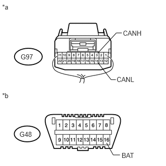
Disconnect the G97 No. 1 junction connector.


b.

Measure the resistance according to the value(s) in the table below.

Standard Resistance:
Tester Connection Switch Condition Specified Condition
G48-6 (CANH) - G48-16 (BAT) Engine switch off 6 kΩ or higher
G48-14 (CANL) - G48-16 (BAT) Engine switch off 6 kΩ or higher


Text in Illustration
*a Front view of DLC3


OK

5.CHECK FOR SHORT TO B+ IN CAN BUS WIRE (NO. 1 JUNCTION CONNECTOR - FOUR WHEEL DRIVE CONTROL ECU)

NG

32.CONNECT CONNECTOR
5.CHECK FOR SHORT TO B+ IN CAN BUS WIRE (NO. 1 JUNCTION CONNECTOR - FOUR WHEEL DRIVE CONTROL ECU)
a.
U148971E01
2.206,2.959 2.344,3.208 2.344,3.208 2.484,3.208 false 2.125,1.291 2.404,1.649 2.404,1.649 2.502,1.649 false 2.627,0.682 2.512,0.682 2.512,0.682 2.125,1.103 false 0.045,0.06 0.282,0.297 0.237,0.237 10 *a 0.045,1.892 0.282,2.129 0.237,0.237 10 *b 2.649,0.605 3.069,0.747 0.420,0.142 10 CANH 2.519,1.564 2.943,1.706 0.424,0.142 10 CANL 2.519,3.14 2.943,3.282 0.424,0.142 10 BAT 0.402,2.702 0.684,2.840 0.282,0.138 10 G48 0.427,1.094 0.708,1.232 0.281,0.138 10 G97

Measure the resistance according to the value(s) in the table below.

Standard Resistance:
Tester Connection Switch Condition Specified Condition
G97-2 (CANH) - G48-16 (BAT) Engine switch off 6 kΩ or higher
G97-13 (CANL) - G48-16 (BAT) Engine switch off 6 kΩ or higher


Text in Illustration
*a Rear view of wire harness connector
(to No. 1 Junction Connector)
*b Front view of DLC3


OK

6.CHECK FOR SHORT TO B+ IN CAN BUS WIRE (NO. 1 JUNCTION CONNECTOR - CERTIFICATION ECU)

NG

10.CONNECT CONNECTOR
6.CHECK FOR SHORT TO B+ IN CAN BUS WIRE (NO. 1 JUNCTION CONNECTOR - CERTIFICATION ECU)
a.
U148972E01
2.206,2.959 2.344,3.208 2.344,3.208 2.484,3.208 false 2.021,1.291 2.3,1.649 2.3,1.649 2.398,1.649 false 2.523,0.682 2.408,0.682 2.408,0.682 2.021,1.103 false 0.045,0.06 0.282,0.297 0.237,0.237 10 *a 0.045,1.892 0.282,2.129 0.237,0.237 10 *b 2.545,0.605 2.964,0.747 0.420,0.142 10 CANH 2.415,1.564 2.839,1.706 0.424,0.142 10 CANL 2.519,3.14 2.943,3.282 0.424,0.142 10 BAT 0.402,2.702 0.684,2.840 0.282,0.138 10 G48 0.427,1.094 0.708,1.232 0.281,0.138 10 G97

Measure the resistance according to the value(s) in the table below.

Standard Resistance:
Tester Connection Switch Condition Specified Condition
G97-3 (CANH) - G48-16 (BAT) Engine switch off 6 kΩ or higher
G97-14 (CANL) - G48-16 (BAT) Engine switch off 6 kΩ or higher


Text in Illustration
*a Rear view of wire harness connector
(to No. 1 Junction Connector)
*b Front view of DLC3


OK

7.CHECK FOR SHORT TO B+ IN CAN BUS WIRE (NO. 1 JUNCTION CONNECTOR - POWER MANAGEMENT CONTROL ECU)

NG

12.CONNECT CONNECTOR
7.CHECK FOR SHORT TO B+ IN CAN BUS WIRE (NO. 1 JUNCTION CONNECTOR - POWER MANAGEMENT CONTROL ECU)
a.
U148973E01
2.206,2.959 2.344,3.208 2.344,3.208 2.484,3.208 false 1.935,1.291 2.214,1.649 2.214,1.649 2.312,1.649 false 2.437,0.682 2.322,0.682 2.322,0.682 1.935,1.103 false 0.045,0.06 0.282,0.297 0.237,0.237 10 *a 0.045,1.892 0.282,2.129 0.237,0.237 10 *b 2.459,0.605 2.879,0.747 0.420,0.142 10 CANH 2.329,1.564 2.753,1.706 0.424,0.142 10 CANL 2.519,3.14 2.943,3.282 0.424,0.142 10 BAT 0.402,2.702 0.684,2.840 0.282,0.138 10 G48 0.427,1.094 0.708,1.232 0.281,0.138 10 G97

Measure the resistance according to the value(s) in the table below.

Standard Resistance:
Tester Connection Switch Condition Specified Condition
G97-4 (CANH) - G48-16 (BAT) Engine switch off 6 kΩ or higher
G97-15 (CANL) - G48-16 (BAT) Engine switch off 6 kΩ or higher


Text in Illustration
*a Rear view of wire harness connector
(to No. 1 Junction Connector)
*b Front view of DLC3


OK

8.CHECK FOR SHORT TO B+ IN CAN BUS WIRE (NO. 1 JUNCTION CONNECTOR - POWER STEERING ECU ASSEMBLY)

NG

14.CONNECT CONNECTOR
8.CHECK FOR SHORT TO B+ IN CAN BUS WIRE (NO. 1 JUNCTION CONNECTOR - POWER STEERING ECU ASSEMBLY)
a.
U148974E01
2.206,2.959 2.344,3.208 2.344,3.208 2.484,3.208 false 1.839,1.291 2.241,1.649 2.241,1.649 2.339,1.649 false 2.464,0.682 2.349,0.682 2.349,0.682 1.839,1.103 false 0.045,0.06 0.282,0.297 0.237,0.237 10 *a 0.045,1.892 0.282,2.129 0.237,0.237 10 *b 2.486,0.605 2.905,0.747 0.420,0.142 10 CANH 2.356,1.564 2.780,1.706 0.424,0.142 10 CANL 2.519,3.14 2.949,3.282 0.431,0.142 10 BAT 0.402,2.702 0.684,2.840 0.282,0.138 10 G48 0.427,1.094 0.708,1.232 0.281,0.138 10 G97

Measure the resistance according to the value(s) in the table below.

Standard Resistance:
Tester Connection Switch Condition Specified Condition
G97-5 (CANH) - G48-16 (BAT) Engine switch off 6 kΩ or higher
G97-16 (CANL) - G48-16 (BAT) Engine switch off 6 kΩ or higher


Text in Illustration
*a Rear view of wire harness connector
(to No. 1 Junction Connector)
*b Front view of DLC3


OK

9.CHECK FOR SHORT TO B+ IN CAN BUS WIRE (NO. 1 JUNCTION CONNECTOR - ECM OR NO. 4 JUNCTION CONNECTOR)

NG

16.CONNECT CONNECTOR
9.CHECK FOR SHORT TO B+ IN CAN BUS WIRE (NO. 1 JUNCTION CONNECTOR - ECM OR NO. 4 JUNCTION CONNECTOR)
a.
U148975E01
2.206,2.959 2.344,3.208 2.344,3.208 2.484,3.208 false 1.729,1.291 2.244,1.649 2.244,1.649 2.341,1.649 false 2.467,0.682 2.352,0.682 2.352,0.682 1.729,1.103 false 0.045,0.06 0.282,0.297 0.237,0.237 10 *a 0.045,1.892 0.282,2.129 0.237,0.237 10 *b 2.489,0.605 2.908,0.747 0.420,0.142 10 CANH 2.359,1.564 2.783,1.706 0.424,0.142 10 CANL 2.519,3.14 2.943,3.282 0.424,0.142 10 BAT 0.402,2.702 0.684,2.840 0.282,0.138 10 G48 0.427,1.094 0.708,1.232 0.281,0.138 10 G97

Measure the resistance according to the value(s) in the table below.

Standard Resistance:
Tester Connection Switch Condition Specified Condition
G97-6 (CANH) - G48-16 (BAT) Engine switch off 6 kΩ or higher
G97-17 (CANL) - G48-16 (BAT) Engine switch off 6 kΩ or higher


Text in Illustration
*a Rear view of wire harness connector
(to No. 1 Junction Connector)
*b Front view of DLC3

Result
Result Proceed to
OK A
NG (for 1GR-FE) B
NG (for 1KD-FTV) C
NG (for 1GD-FTV) D
NG (for 2TR-FE) E


A

REPLACE NO. 1 JUNCTION CONNECTOR

B

18.CONNECT CONNECTOR

C

20.CONNECT CONNECTOR

D

22.CONNECT CONNECTOR

E

24.CONNECT CONNECTOR
10.CONNECT CONNECTOR
a.

Reconnect the G97 No. 1 junction connector.


NEXT
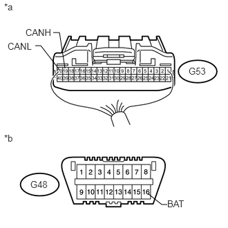
11.CHECK FOR SHORT TO B+ IN CAN BUS WIRE (FOUR WHEEL DRIVE CONTROL ECU)
a.
U148675E04
2.229,2.917 2.438,3.083 2.438,3.083 2.521,3.083 false 0.979,1.031 0.896,0.49 0.896,0.49 0.802,0.49 false 0.896,1.052 0.615,0.688 0.615,0.688 0.531,0.688 false 2.844,0.99 3.125,1.167 0.281,0.177 10 false G53 0.458,2.698 0.781,2.875 0.323,0.177 10 false G48 0.063,0.021 0.271,0.198 0.208,0.177 10 false *a 0.063,2 0.271,2.177 0.208,0.177 10 false *b 2.521,2.99 2.958,3.167 0.438,0.177 10 false BAT 0.385,0.406 0.802,0.583 0.417,0.177 10 false CANH 0.115,0.615 0.51,0.792 0.396,0.177 10 false CANL

Disconnect the G53 four wheel drive control ECU connector.


b.

Measure the resistance according to the value(s) in the table below.

Standard Resistance:
Tester Connection Switch Condition Specified Condition
G53-19 (CANH) - G48-16 (BAT) Engine switch off 6 kΩ or higher
G53-20 (CANL) - G48-16 (BAT) Engine switch off 6 kΩ or higher


Text in Illustration
*a Rear view of wire harness connector
(to Four Wheel Drive Control ECU)
*b Front view of DLC3


OK

REPLACE FOUR WHEEL DRIVE CONTROL ECU

NG

REPAIR OR REPLACE CAN BRANCH WIRE CONNECTED TO FOUR WHEEL DRIVE CONTROL ECU (CANH, CANL)

12.CONNECT CONNECTOR
a.

Reconnect the G97 No. 1 junction connector.


NEXT
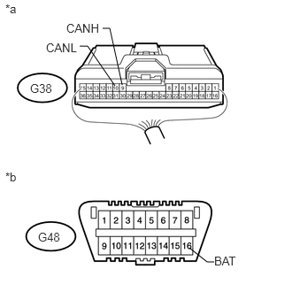
13.CHECK FOR SHORT TO B+ IN CAN BUS WIRE (CERTIFICATION ECU)
a.
U148689E04
2.229,2.917 2.438,3.083 2.438,3.083 2.521,3.083 false 1.354,1.01 1.031,0.542 1.031,0.542 0.938,0.542 false 1.438,1 1.292,0.333 1.292,0.333 1.208,0.333 false 0.354,0.958 0.719,1.135 0.365,0.177 10 false G38 0.448,2.708 0.771,2.885 0.323,0.177 10 false G48 0.063,0.021 0.271,0.198 0.208,0.177 10 false *a 0.063,2 0.271,2.177 0.208,0.177 10 false *b 2.521,2.99 2.958,3.167 0.438,0.177 10 false BAT 0.781,0.25 1.198,0.427 0.417,0.177 10 false CANH 0.542,0.479 0.938,0.646 0.396,0.167 10 false CANL

Disconnect the G38 certification ECU (smart key ECU assembly) connector.


b.

Measure the resistance according to the value(s) in the table below.

Standard Resistance:
Tester Connection Switch Condition Specified Condition
G38-9 (CANH) - G48-16 (BAT) Engine switch off 6 kΩ or higher
G38-10 (CANL) - G48-16 (BAT) Engine switch off 6 kΩ or higher


Text in Illustration
*a Rear view of wire harness connector
(to Certification ECU [Smart Key ECU Assembly])
*b Front view of DLC3


OK

REPLACE CERTIFICATION ECU (SMART KEY ECU ASSEMBLY)

NG

REPAIR OR REPLACE CAN BRANCH WIRE CONNECTED TO CERTIFICATION ECU (CANH, CANL)

14.CONNECT CONNECTOR
a.

Reconnect the G97 No. 1 junction connector.


NEXT
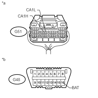
15.CHECK FOR SHORT TO B+ IN CAN BUS WIRE (POWER MANAGEMENT CONTROL ECU)
a.
U148663E04
2.229,2.917 2.438,3.083 2.438,3.083 2.521,3.083 false 1.604,1.115 1.385,0.354 1.385,0.354 1.302,0.354 false 1.531,1.115 1.125,0.552 1.125,0.552 1.042,0.552 false 0.51,1.021 0.792,1.198 0.281,0.177 10 false G51 0.448,2.708 0.771,2.885 0.323,0.177 10 false G48 0.063,0.021 0.271,0.198 0.208,0.177 10 false *a 0.063,2 0.271,2.177 0.208,0.177 10 false *b 2.521,2.99 2.958,3.167 0.438,0.177 10 false BAT 0.625,0.479 1.021,0.656 0.396,0.177 10 false CA1H 0.917,0.26 1.292,0.438 0.375,0.177 10 false CA1L

Disconnect the G51 power management control ECU connector.


b.

Measure the resistance according to the value(s) in the table below.

Standard Resistance:
Tester Connection Switch Condition Specified Condition
G51-14 (CA1H) - G48-16 (BAT) Engine switch off 6 kΩ or higher
G51-13 (CA1L) - G48-16 (BAT) Engine switch off 6 kΩ or higher


Text in Illustration
*a Rear view of wire harness connector
(to Power Management Control ECU)
*b Front view of DLC3


OK

NG

REPAIR OR REPLACE CAN BRANCH WIRE CONNECTED TO POWER MANAGEMENT CONTROL ECU (CA1H, CA1L)

16.CONNECT CONNECTOR
a.

Reconnect the G97 No. 1 junction connector.


NEXT
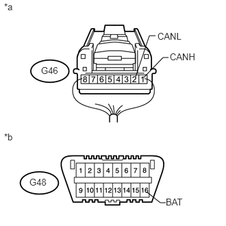
17.CHECK FOR SHORT TO B+ IN CAN BUS WIRE (POWER STEERING ECU ASSEMBLY)
a.
U148674E02
2.229,2.917 2.438,3.083 2.438,3.083 2.521,3.083 false 2.063,1.167 2.271,0.542 2.271,0.542 2.365,0.542 false 2.188,1.177 2.479,0.875 2.479,0.875 2.563,0.875 false 0.625,0.99 0.927,1.167 0.302,0.177 10 false G46 0.448,2.688 0.771,2.865 0.323,0.177 10 false G48 0.063,0.021 0.271,0.198 0.208,0.177 10 false *a 0.063,2 0.271,2.177 0.208,0.177 10 false *b 2.521,2.99 2.958,3.167 0.438,0.177 10 false BAT 2.583,0.781 3,0.958 0.417,0.177 10 false CANH 2.396,0.469 2.792,0.646 0.396,0.177 10 false CANL

Disconnect the G46 power steering ECU assembly connector.


b.

Measure the resistance according to the value(s) in the table below.

Standard Resistance:
Tester Connection Switch Condition Specified Condition
G46-1 (CANH) - G48-16 (BAT) Engine switch off 6 kΩ or higher
G46-2 (CANL) - G48-16 (BAT) Engine switch off 6 kΩ or higher


Text in Illustration
*a Rear view of wire harness connector
(to Power Steering ECU Assembly)
*b Front view of DLC3


OK

REPLACE POWER STEERING ECU ASSEMBLY

NG

REPAIR OR REPLACE CAN BRANCH WIRE CONNECTED TO POWER STEERING ECU ASSEMBLY (CANH, CANL)

18.CONNECT CONNECTOR
a.

Reconnect the G97 No. 1 junction connector.


NEXT
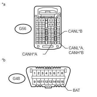
19.CHECK FOR SHORT TO B+ IN CAN BUS WIRE (ECM)
a.
U170190E01
0.449,2.694 0.736,2.872 0.287,0.178 10 G48 0.672,0.924 0.976,1.102 0.303,0.178 10 G56 0.062,0.061 0.275,0.239 0.213,0.178 10 *a 0.062,2.041 0.275,2.219 0.213,0.178 10 *b 2.434,1.619 3.070,1.974 0.636,0.355 10 CANL*A, CANH*B 2.103,1.524 2.314,1.709 2.314,1.709 2.402,1.709 false 0.787,1.833 1.435,2.011 0.648,0.178 10 CANH*A 1.857,1.52 1.604,1.917 1.604,1.917 1.516,1.917 false 2.205,2.961 2.404,3.201 2.404,3.201 2.544,3.201 false 2.582,3.114 3.006,3.256 0.424,0.142 10 BAT 2.415,1.018 3.248,1.373 0.834,0.355 10 CANL*B 2.072,1.264 2.295,1.107 2.295,1.107 2.383,1.107 false

Disconnect the G56 ECM connector.


b.

Measure the resistance according to the value(s) in the table below.

Standard Resistance:
for Manual Transmission System
Tester Connection Switch Condition Specified Condition
G56-32 (CANH) - G48-16 (BAT) Engine switch off 6 kΩ or higher
G56-31 (CANL) - G48-16 (BAT) Engine switch off 6 kΩ or higher

for Automatic Transmission System
Tester Connection Switch Condition Specified Condition
G56-31 (CANH) - G48-16 (BAT) Engine switch off 6 kΩ or higher
G56-25 (CANL) - G48-16 (BAT) Engine switch off 6 kΩ or higher


Text in Illustration
*A for Manual Transmission System
*B for Automatic Transmission System
*a Rear view of wire harness connector
(to ECM)
*b Front view of DLC3


OK

NG

REPAIR OR REPLACE CAN MAIN WIRE CONNECTED TO ECM (CANH, CANL)

20.CONNECT CONNECTOR
a.

Reconnect the G97 No. 1 junction connector.


NEXT
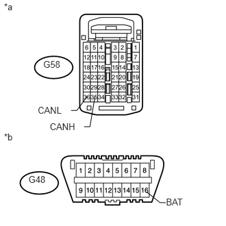
21.CHECK FOR SHORT TO B+ IN CAN BUS WIRE (ECM)
a.
U170184E01
0.433,2.643 0.721,2.821 0.287,0.178 10 G48 0.658,0.901 0.939,1.038 0.280,0.137 10 G58 0.062,0.016 0.275,0.194 0.213,0.178 10 *a 0.062,1.997 0.275,2.175 0.213,0.178 10 *b 2.525,2.987 2.958,3.165 0.434,0.178 10 BAT 2.229,2.918 2.434,3.082 2.434,3.082 2.521,3.082 false 0.574,1.597 1.005,1.734 0.431,0.137 10 CANL 1.327,1.462 1.168,1.68 1.168,1.68 1.081,1.68 false 0.757,1.844 1.188,1.981 0.431,0.137 10 CANH 1.444,1.462 1.368,1.927 1.368,1.927 1.28,1.927 false

Disconnect the G58 ECM connector.


b.

Measure the resistance according to the value(s) in the table below.

Standard Resistance:
Tester Connection Switch Condition Specified Condition
G58-35 (CANH) - G48-16 (BAT) Engine switch off 6 kΩ or higher
G58-36 (CANL) - G48-16 (BAT) Engine switch off 6 kΩ or higher


Text in Illustration
*a Rear view of wire harness connector
(to ECM)
*b Front view of DLC3


OK

NG

REPAIR OR REPLACE CAN MAIN WIRE CONNECTED TO ECM (CANH, CANL)

22.CONNECT CONNECTOR
a.

Reconnect the G97 No. 1 junction connector.


NEXT
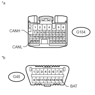
23.CHECK FOR SHORT TO B+ IN CAN BUS WIRE (ECM)
a.
U170537E02
2.229,2.917 2.406,3.125 2.406,3.125 2.49,3.125 false 1.115,1.281 0.854,1.094 0.854,1.094 0.771,1.094 false 1.125,1.51 0.927,1.688 0.927,1.688 0.833,1.688 false 0.469,2.688 0.76,2.865 0.292,0.177 10 false G48 2.76,1.073 3.198,1.302 0.438,0.229 10 false G184 0.063,0.021 0.271,0.198 0.208,0.177 10 false *a 0.063,2 0.271,2.177 0.208,0.177 10 false *b 2.542,3.031 2.979,3.208 0.438,0.177 10 false BAT 0.448,1.615 0.896,1.844 0.448,0.229 10 false CANL 0.344,1.031 0.813,1.24 0.469,0.208 10 false CANH

Disconnect the G184 ECM connector.


b.

Measure the resistance according to the value(s) in the table below.

Standard Resistance:
Tester Connection Switch Condition Specified Condition
G184-17 (CANH) - G48-16 (BAT) Engine switch off 6 kΩ or higher
G184-28 (CANL) - G48-16 (BAT) Engine switch off 6 kΩ or higher


Text in Illustration
*a Front view of wire harness connector
(to ECM)
*b Front view of DLC3


OK

NG

REPAIR OR REPLACE CAN MAIN WIRE CONNECTED TO ECM (CANH, CANL)

24.CONNECT CONNECTOR
a.

Reconnect the G97 No. 1 junction connector.


NEXT
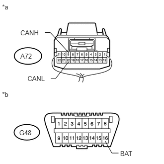
25.CHECK FOR SHORT TO B+ IN CAN BUS WIRE (NO. 4 JUNCTION CONNECTOR - NO. 1 JUNCTION CONNECTOR)
a.
U148976E01
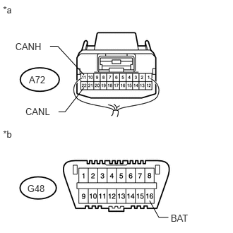
2.206,2.959 2.344,3.208 2.344,3.208 2.484,3.208 false 1.441,1.291 1.162,1.649 1.162,1.649 1.065,1.649 false 0.939,0.682 1.054,0.682 1.054,0.682 1.441,1.103 false 0.045,0.06 0.282,0.297 0.237,0.237 10 *a 0.045,1.892 0.282,2.129 0.237,0.237 10 *b 0.426,0.605 0.846,0.747 0.420,0.142 10 CANH 0.576,1.564 1.000,1.706 0.424,0.142 10 CANL 2.519,3.14 2.943,3.282 0.424,0.142 10 BAT 0.402,2.702 0.684,2.840 0.282,0.138 10 G48 0.427,1.094 0.708,1.232 0.281,0.138 10 A72

Disconnect the A72 No. 4 junction connector.


b.

Measure the resistance according to the value(s) in the table below.

Standard Resistance:
Tester Connection Switch Condition Specified Condition
A72-9 (CANH) - G48-16 (BAT) Engine switch off 6 kΩ or higher
A72-20 (CANL) - G48-16 (BAT) Engine switch off 6 kΩ or higher


Text in Illustration
*a Rear view of wire harness connector
(to No. 4 Junction Connector)
*b Front view of DLC3


OK

26.CHECK FOR SHORT TO B+ IN CAN BUS WIRE (NO. 4 JUNCTION CONNECTOR - SKID CONTROL ECU)

NG

REPAIR OR REPLACE CAN MAIN WIRE OR CONNECTOR (NO. 4 JUNCTION CONNECTOR - NO. 1 JUNCTION CONNECTOR)

26.CHECK FOR SHORT TO B+ IN CAN BUS WIRE (NO. 4 JUNCTION CONNECTOR - SKID CONTROL ECU)
a.
U148977E01
2.206,2.959 2.344,3.208 2.344,3.208 2.484,3.208 false 1.239,1.291 0.96,1.649 0.96,1.649 0.863,1.649 false 0.738,0.682 0.852,0.682 0.852,0.682 1.239,1.103 false 0.045,0.06 0.282,0.297 0.237,0.237 10 *a 0.045,1.892 0.282,2.129 0.237,0.237 10 *b 0.224,0.605 0.644,0.747 0.420,0.142 10 CANH 0.374,1.564 0.798,1.706 0.424,0.142 10 CANL 2.519,3.14 2.943,3.282 0.424,0.142 10 BAT 0.402,2.702 0.684,2.840 0.282,0.138 10 G48 0.427,1.094 0.708,1.232 0.281,0.138 10 A72

Measure the resistance according to the value(s) in the table below.

Standard Resistance:
Tester Connection Switch Condition Specified Condition
A72-11 (CANH) - G48-16 (BAT) Engine switch off 6 kΩ or higher
A72-22 (CANL) - G48-16 (BAT) Engine switch off 6 kΩ or higher


Text in Illustration
*a Rear view of wire harness connector
(to No. 4 Junction Connector)
*b Front view of DLC3


OK

27.CHECK FOR SHORT TO B+ IN CAN BUS WIRE (NO. 4 JUNCTION CONNECTOR - ECM)

NG

28.CONNECT CONNECTOR
27.CHECK FOR SHORT TO B+ IN CAN BUS WIRE (NO. 4 JUNCTION CONNECTOR - ECM)
a.
U148978E01
2.206,2.959 2.344,3.208 2.344,3.208 2.484,3.208 false 1.332,1.291 1.053,1.649 1.053,1.649 0.956,1.649 false 0.83,0.682 0.945,0.682 0.945,0.682 1.332,1.103 false 0.045,0.06 0.282,0.297 0.237,0.237 10 *a 0.045,1.892 0.282,2.129 0.237,0.237 10 *b 0.317,0.605 0.737,0.747 0.420,0.142 10 CANH 0.467,1.564 0.891,1.706 0.424,0.142 10 CANL 2.519,3.14 2.943,3.282 0.424,0.142 10 BAT 0.402,2.702 0.684,2.840 0.282,0.138 10 G48 0.427,1.094 0.708,1.232 0.281,0.138 10 A72

Measure the resistance according to the value(s) in the table below.

Standard Resistance:
Tester Connection Switch Condition Specified Condition
A72-10 (CANH) - G48-16 (BAT) Engine switch off 6 kΩ or higher
A72-21 (CANL) - G48-16 (BAT) Engine switch off 6 kΩ or higher


Text in Illustration
*a Rear view of wire harness connector
(to No. 4 Junction Connector)
*b Front view of DLC3


OK

REPLACE NO. 4 JUNCTION CONNECTOR

NG

30.CONNECT CONNECTOR
28.CONNECT CONNECTOR
a.

Reconnect the A72 No. 4 junction connector.


NEXT
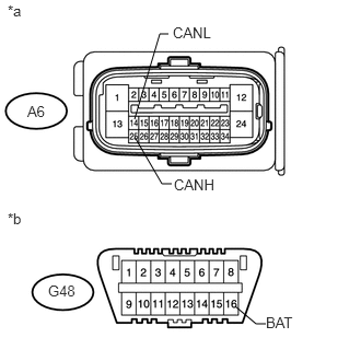
29.CHECK FOR SHORT TO B+ IN CAN BUS WIRE (SKID CONTROL ECU)
a.
U148737E03
2.24,2.917 2.438,3.083 2.438,3.083 2.531,3.083 false 1.281,1.302 1.542,1.75 1.542,1.75 1.635,1.75 false 1.281,1.135 1.521,0.323 1.521,0.323 1.604,0.323 false 0.26,0.979 0.542,1.156 0.281,0.177 10 false A6 0.458,2.688 0.781,2.865 0.323,0.177 10 false G48 0.073,0.021 0.281,0.198 0.208,0.177 10 false *a 0.073,2 0.281,2.177 0.208,0.177 10 false *b 2.531,2.99 2.969,3.167 0.438,0.177 10 false BAT 1.656,1.677 2.094,1.854 0.438,0.177 10 false CANH 1.646,0.229 2.083,0.406 0.438,0.177 10 false CANL

Disconnect the A6 brake actuator assembly (skid control ECU) connector.


b.

Measure the resistance according to the value(s) in the table below.

Standard Resistance:
Tester Connection Switch Condition Specified Condition
A6-25 (CANH) - G48-16 (BAT) Engine switch off 6 kΩ or higher
A6-14 (CANL) - G48-16 (BAT) Engine switch off 6 kΩ or higher


Text in Illustration
*a Front view of wire harness connector
(to Brake Actuator Assembly [Skid Control ECU])
*b Front view of DLC3


OK

REPLACE BRAKE ACTUATOR ASSEMBLY (SKID CONTROL ECU)

NG

REPAIR OR REPLACE CAN BRANCH WIRE CONNECTED TO SKID CONTROL ECU (CANH, CANL)

30.CONNECT CONNECTOR
a.

Reconnect the A72 No. 4 junction connector.


NEXT
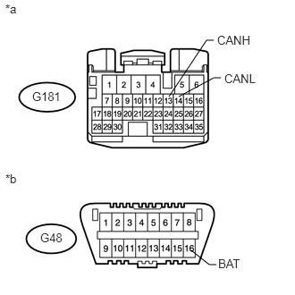
31.CHECK FOR SHORT TO B+ IN CAN BUS WIRE (ECM)
a.
U170534E02
2.229,2.917 2.438,3.083 2.438,3.083 2.521,3.083 false 2.083,1.125 2.49,0.906 2.49,0.906 2.573,0.906 false 1.969,1.125 2.406,0.469 2.406,0.469 2.49,0.469 false 0.469,2.688 0.76,2.865 0.292,0.177 10 false G48 0.375,1.042 0.75,1.25 0.375,0.208 10 false G181 0.063,0.021 0.271,0.198 0.208,0.177 10 false *a 0.063,2 0.271,2.177 0.208,0.177 10 false *b 2.542,2.99 2.979,3.167 0.438,0.177 10 false BAT 2.615,0.833 3.104,1.042 0.49,0.208 10 false CANL 2.531,0.385 3.01,0.573 0.479,0.188 10 false CANH

Disconnect the G181 ECM connector.


b.

Measure the resistance according to the value(s) in the table below.

Standard Resistance:
Tester Connection Switch Condition Specified Condition
G181-13 (CANH) - G48-16 (BAT) Engine switch off 6 kΩ or higher
G181-14 (CANL) - G48-16 (BAT) Engine switch off 6 kΩ or higher


Text in Illustration
*a Front view of wire harness connector
(to ECM)
*b Front view of DLC3


OK

NG

REPAIR OR REPLACE CAN MAIN WIRE CONNECTED TO ECM (CANH, CANL)

32.CONNECT CONNECTOR
a.

Reconnect the G97 No. 1 junction connector.


NEXT
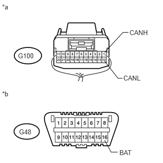
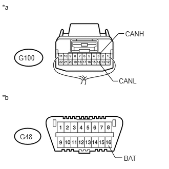
33.CHECK FOR SHORT TO B+ IN CAN BUS WIRE (NO. 2 JUNCTION CONNECTOR - NO. 1 JUNCTION CONNECTOR)
a.
U148979E01
2.206,2.959 2.344,3.208 2.344,3.208 2.484,3.208 false 2.207,1.291 2.486,1.649 2.486,1.649 2.584,1.649 false 2.709,0.682 2.594,0.682 2.594,0.682 2.207,1.103 false 0.045,0.06 0.282,0.297 0.237,0.237 10 *a 0.045,1.892 0.282,2.129 0.237,0.237 10 *b 2.731,0.605 3.151,0.747 0.420,0.142 10 CANH 2.601,1.564 3.025,1.706 0.424,0.142 10 CANL 2.519,3.14 2.943,3.282 0.424,0.142 10 BAT 0.402,2.702 0.684,2.840 0.282,0.138 10 G48 0.379,1.094 0.740,1.232 0.362,0.138 10 G100

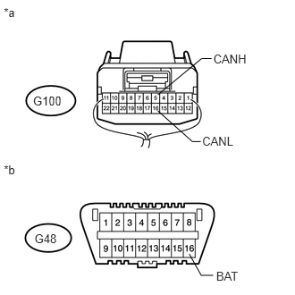
Disconnect the G100 No. 2 junction connector.


b.

Measure the resistance according to the value(s) in the table below.

Standard Resistance:
Tester Connection Switch Condition Specified Condition
G100-1 (CANH) - G48-16 (BAT) Engine switch off 6 kΩ or higher
G100-12 (CANL) - G48-16 (BAT) Engine switch off 6 kΩ or higher


Text in Illustration
*a Rear view of wire harness connector
(to No. 2 Junction Connector)
*b Front view of DLC3


OK

34.CHECK FOR SHORT TO B+ IN CAN BUS WIRE (NO. 2 JUNCTION CONNECTOR SIDE)

NG

REPAIR OR REPLACE CAN MAIN WIRE OR CONNECTOR (NO. 2 JUNCTION CONNECTOR - NO. 1 JUNCTION CONNECTOR)

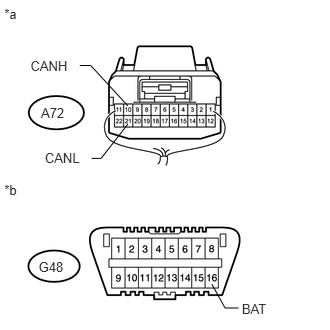
34.CHECK FOR SHORT TO B+ IN CAN BUS WIRE (NO. 2 JUNCTION CONNECTOR SIDE)
a.
U148271E08
1.979,0.906 2.167,0.406 2.167,0.406 2.292,0.406 false 1.958,1.448 1.813,1.875 1.813,1.875 1.677,1.875 false 2.323,1.458 2.469,1.885 2.469,1.885 2.604,1.885 false 0.094,0 0.26,0.188 0.167,0.188 10 false *a 2.375,0.323 2.844,0.51 0.469,0.188 10 false CANH 1.292,1.792 1.698,1.979 0.406,0.188 10 false CANL 0.26,1.115 0.552,1.302 0.292,0.188 10 false G48 2.667,1.802 2.979,1.958 0.313,0.156 10 false BAT

Measure the resistance according to the value(s) in the table below.

Standard Resistance:
Tester Connection Switch Condition Specified Condition
G48-6 (CANH) - G48-16 (BAT) Engine switch off 6 kΩ or higher
G48-14 (CANL) - G48-16 (BAT) Engine switch off 6 kΩ or higher


Text in Illustration
*a Front view of DLC3


OK

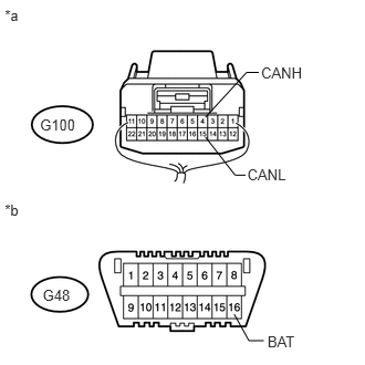
35.CHECK FOR SHORT TO B+ IN CAN BUS WIRE (NO. 2 JUNCTION CONNECTOR - NAVIGATION RECEIVER ASSEMBLY)

NG

50.CONNECT CONNECTOR
35.CHECK FOR SHORT TO B+ IN CAN BUS WIRE (NO. 2 JUNCTION CONNECTOR - NAVIGATION RECEIVER ASSEMBLY)
NOTICE:

For vehicles without a navigation system (for navigation receiver type), go to "Check for Short to B+ in CAN Bus Wire (No. 2 Junction Connector - Radio and Display Receiver Assembly)".
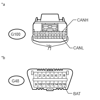

a.
U148980E01
2.206,2.959 2.344,3.208 2.344,3.208 2.484,3.208 false 2.125,1.291 2.404,1.649 2.404,1.649 2.502,1.649 false 2.627,0.682 2.512,0.682 2.512,0.682 2.125,1.103 false 0.045,0.06 0.282,0.297 0.237,0.237 10 *a 0.045,1.892 0.282,2.129 0.237,0.237 10 *b 2.649,0.605 3.069,0.747 0.420,0.142 10 CANH 2.519,1.564 2.943,1.706 0.424,0.142 10 CANL 2.519,3.14 2.943,3.282 0.424,0.142 10 BAT 0.402,2.702 0.684,2.840 0.282,0.138 10 G48 0.372,1.094 0.737,1.232 0.365,0.138 10 G100

Measure the resistance according to the value(s) in the table below.

Standard Resistance:
Tester Connection Switch Condition Specified Condition
G100-2 (CANH) - G48-16 (BAT) Engine switch off 6 kΩ or higher
G100-13 (CANL) - G48-16 (BAT) Engine switch off 6 kΩ or higher


Text in Illustration
*a Rear view of wire harness connector
(to No. 2 Junction Connector)
*b Front view of DLC3


OK

36.CHECK FOR SHORT TO B+ IN CAN BUS WIRE (NO. 2 JUNCTION CONNECTOR - RADIO AND DISPLAY RECEIVER ASSEMBLY)

NG

40.CONNECT CONNECTOR
36.CHECK FOR SHORT TO B+ IN CAN BUS WIRE (NO. 2 JUNCTION CONNECTOR - RADIO AND DISPLAY RECEIVER ASSEMBLY)
NOTICE:

For vehicles with a navigation system (for navigation receiver type), go to "Check for Short to B+ in CAN Bus Wire (No. 2 Junction Connector - Steering Angle Sensor)".


a.
U148980E01
2.206,2.959 2.344,3.208 2.344,3.208 2.484,3.208 false 2.125,1.291 2.404,1.649 2.404,1.649 2.502,1.649 false 2.627,0.682 2.512,0.682 2.512,0.682 2.125,1.103 false 0.045,0.06 0.282,0.297 0.237,0.237 10 *a 0.045,1.892 0.282,2.129 0.237,0.237 10 *b 2.649,0.605 3.069,0.747 0.420,0.142 10 CANH 2.519,1.564 2.943,1.706 0.424,0.142 10 CANL 2.519,3.14 2.943,3.282 0.424,0.142 10 BAT 0.402,2.702 0.684,2.840 0.282,0.138 10 G48 0.372,1.094 0.737,1.232 0.365,0.138 10 G100

Measure the resistance according to the value(s) in the table below.

Standard Resistance:
Tester Connection Switch Condition Specified Condition
G100-2 (CANH) - G48-16 (BAT) Engine switch off 6 kΩ or higher
G100-13 (CANL) - G48-16 (BAT) Engine switch off 6 kΩ or higher


Text in Illustration
*a Rear view of wire harness connector
(to No. 2 Junction Connector)
*b Front view of DLC3


OK

37.CHECK FOR SHORT TO B+ IN CAN BUS WIRE (NO. 2 JUNCTION CONNECTOR - STEERING ANGLE SENSOR)

NG

42.CONNECT CONNECTOR
37.CHECK FOR SHORT TO B+ IN CAN BUS WIRE (NO. 2 JUNCTION CONNECTOR - STEERING ANGLE SENSOR)
a.
U148981E01
2.206,2.959 2.344,3.208 2.344,3.208 2.484,3.208 false 2.021,1.291 2.3,1.649 2.3,1.649 2.398,1.649 false 2.523,0.682 2.408,0.682 2.408,0.682 2.021,1.103 false 0.045,0.06 0.282,0.297 0.237,0.237 10 *a 0.045,1.892 0.282,2.129 0.237,0.237 10 *b 2.545,0.605 2.964,0.747 0.420,0.142 10 CANH 2.415,1.564 2.839,1.706 0.424,0.142 10 CANL 2.519,3.14 2.943,3.282 0.424,0.142 10 BAT 0.402,2.702 0.684,2.840 0.282,0.138 10 G48 0.375,1.094 0.735,1.232 0.360,0.138 10 G100

Measure the resistance according to the value(s) in the table below.

Standard Resistance:
Tester Connection Switch Condition Specified Condition
G100-3 (CANH) - G48-16 (BAT) Engine switch off 6 kΩ or higher
G100-14 (CANL) - G48-16 (BAT) Engine switch off 6 kΩ or higher


Text in Illustration
*a Rear view of wire harness connector
(to No. 2 Junction Connector)
*b Front view of DLC3


OK

38.CHECK FOR SHORT TO B+ IN CAN BUS WIRE (NO. 2 JUNCTION CONNECTOR - YAW RATE SENSOR ASSEMBLY)

NG

44.CONNECT CONNECTOR
38.CHECK FOR SHORT TO B+ IN CAN BUS WIRE (NO. 2 JUNCTION CONNECTOR - YAW RATE SENSOR ASSEMBLY)
a.
U148982E01
2.206,2.959 2.344,3.208 2.344,3.208 2.484,3.208 false 1.935,1.291 2.214,1.649 2.214,1.649 2.312,1.649 false 2.437,0.682 2.322,0.682 2.322,0.682 1.935,1.103 false 0.045,0.06 0.282,0.297 0.237,0.237 10 *a 0.045,1.892 0.282,2.129 0.237,0.237 10 *b 2.459,0.605 2.879,0.747 0.420,0.142 10 CANH 2.329,1.564 2.753,1.706 0.424,0.142 10 CANL 2.519,3.14 2.943,3.282 0.424,0.142 10 BAT 0.402,2.702 0.684,2.840 0.282,0.138 10 G48 0.377,1.094 0.735,1.232 0.358,0.138 10 G100

Measure the resistance according to the value(s) in the table below.

Standard Resistance:
Tester Connection Switch Condition Specified Condition
G100-4 (CANH) - G48-16 (BAT) Engine switch off 6 kΩ or higher
G100-15 (CANL) - G48-16 (BAT) Engine switch off 6 kΩ or higher


Text in Illustration
*a Rear view of wire harness connector
(to No. 2 Junction Connector)
*b Front view of DLC3


OK

39.CHECK FOR SHORT TO B+ IN CAN BUS WIRE (NO. 2 JUNCTION CONNECTOR - CENTER AIRBAG SENSOR ASSEMBLY)

NG

46.CONNECT CONNECTOR
39.CHECK FOR SHORT TO B+ IN CAN BUS WIRE (NO. 2 JUNCTION CONNECTOR - CENTER AIRBAG SENSOR ASSEMBLY)
a.
U148983E01
2.206,2.959 2.344,3.208 2.344,3.208 2.484,3.208 false 1.839,1.291 2.241,1.649 2.241,1.649 2.339,1.649 false 2.464,0.682 2.349,0.682 2.349,0.682 1.839,1.103 false 0.045,0.06 0.282,0.297 0.237,0.237 10 *a 0.045,1.892 0.282,2.129 0.237,0.237 10 *b 2.486,0.605 2.905,0.747 0.420,0.142 10 CANH 2.356,1.564 2.780,1.706 0.424,0.142 10 CANL 2.519,3.14 2.949,3.282 0.431,0.142 10 BAT 0.402,2.702 0.684,2.840 0.282,0.138 10 G48 0.385,1.094 0.743,1.232 0.358,0.138 10 G100

Measure the resistance according to the value(s) in the table below.

Standard Resistance:
Tester Connection Switch Condition Specified Condition
G100-5 (CANH) - G48-16 (BAT) Engine switch off 6 kΩ or higher
G100-16 (CANL) - G48-16 (BAT) Engine switch off 6 kΩ or higher


Text in Illustration
*a Rear view of wire harness connector
(to No. 2 Junction Connector)
*b Front view of DLC3


OK

REPLACE NO. 2 JUNCTION CONNECTOR

NG

48.CONNECT CONNECTOR
40.CONNECT CONNECTOR
a.

Reconnect the G100 No. 2 junction connector.


NEXT
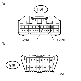
41.CHECK FOR SHORT TO B+ IN CAN BUS WIRE (NAVIGATION RECEIVER ASSEMBLY)
a.
U170272E01
0.378,2.688 0.659,2.828 0.281,0.140 10 G48 1.578,0.311 1.863,0.451 0.286,0.140 10 H56 0.088,0.077 0.353,0.219 0.265,0.142 10 *a 0.088,0.077 0.353,0.219 0.265,0.142 10 *a 0.088,1.765 0.353,1.907 0.265,0.142 10 *b 2.394,1.689 2.282,1.689 2.282,1.689 1.983,1.175 false 1.444,1.689 1.556,1.689 1.556,1.689 1.856,1.175 false 0.913,1.6 1.356,1.740 0.443,0.140 10 CANH 2.421,1.6 2.864,1.740 0.443,0.140 10 CANL 2.184,2.927 2.316,3.148 2.316,3.148 2.456,3.148 false 2.486,3.05 2.909,3.192 0.424,0.142 10 BAT

Disconnect the H56 radio and display receiver assembly connector.


b.

Measure the resistance according to the value(s) in the table below.

Standard Resistance:
Tester Connection Switch Condition Specified Condition
H56-9 (CANH) - G48-16 (BAT) Engine switch off 6 kΩ or higher
H56-10 (CANL) - G48-16 (BAT) Engine switch off 6 kΩ or higher


Text in Illustration
*a Front view of wire harness connector
(to Navigation Receiver Assembly)
*b Front view of DLC3


OK

NG

REPAIR OR REPLACE CAN BRANCH WIRE CONNECTED TO NAVIGATION RECEIVER ASSEMBLY (CANH, CANL)

42.CONNECT CONNECTOR
a.

Reconnect the G100 No. 2 junction connector.


NEXT
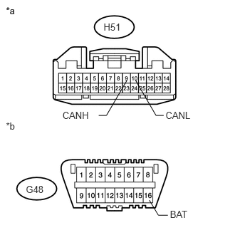
43.CHECK FOR SHORT TO B+ IN CAN BUS WIRE (RADIO AND DISPLAY RECEIVER ASSEMBLY)
a.
U148883E01
0.378,2.688 0.659,2.828 0.281,0.140 10 G48 1.515,0.311 1.800,0.451 0.286,0.140 10 H51 0.088,0.077 0.353,0.219 0.265,0.142 10 *a 0.088,0.077 0.353,0.219 0.265,0.142 10 *a 0.088,1.765 0.353,1.907 0.265,0.142 10 *b 2.394,1.689 2.282,1.689 2.282,1.689 1.983,1.175 false 1.444,1.689 1.556,1.689 1.556,1.689 1.856,1.175 false 0.913,1.6 1.356,1.740 0.443,0.140 10 CANH 2.421,1.6 2.864,1.740 0.443,0.140 10 CANL 2.184,2.927 2.316,3.148 2.316,3.148 2.456,3.148 false 2.486,3.05 2.909,3.192 0.424,0.142 10 BAT

Disconnect the H51 radio and display receiver assembly connector.


b.

Measure the resistance according to the value(s) in the table below.

Standard Resistance:
Tester Connection Switch Condition Specified Condition
H51-9 (CANH) - G48-16 (BAT) Engine switch off 6 kΩ or higher
H51-10 (CANL) - G48-16 (BAT) Engine switch off 6 kΩ or higher


Text in Illustration
*a Front view of wire harness connector
(to Radio and Display Receiver Assembly)
*b Front view of DLC3


OK

NG

REPAIR OR REPLACE CAN BRANCH WIRE CONNECTED TO RADIO AND DISPLAY RECEIVER ASSEMBLY (CANH, CANL)

44.CONNECT CONNECTOR
a.

Reconnect the G100 No. 2 junction connector.


NEXT
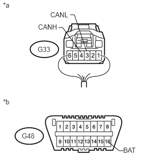
45.CHECK FOR SHORT TO B+ IN CAN BUS WIRE (STEERING ANGLE SENSOR)
a.
U148671E03
1.771,1.052 1.521,0.302 1.521,0.302 1.438,0.302 false 1.656,1.073 1.281,0.563 1.281,0.563 1.198,0.563 false 2.229,2.917 2.438,3.083 2.438,3.083 2.521,3.083 false 0.771,0.927 1.073,1.104 0.302,0.177 10 false G33 0.781,0.469 1.188,0.646 0.406,0.177 10 false CANH 1.031,0.219 1.427,0.396 0.396,0.177 10 false CANL 0.448,2.698 0.771,2.875 0.323,0.177 10 false G48 0.063,0.021 0.271,0.198 0.208,0.177 10 false *a 0.063,2 0.271,2.177 0.208,0.177 10 false *b 2.521,2.99 2.958,3.167 0.438,0.177 10 false BAT

Disconnect the G33 spiral cable sub-assembly (steering angle sensor) connector.


b.

Measure the resistance according to the value(s) in the table below.

Standard Resistance:
Tester Connection Switch Condition Specified Condition
G33-4 (CANH) - G48-16 (BAT) Engine switch off 6 kΩ or higher
G33-3 (CANL) - G48-16 (BAT) Engine switch off 6 kΩ or higher


Text in Illustration
*a Rear view of wire harness connector
(to Spiral Cable Sub-assembly [Steering Angle Sensor])
*b Front view of DLC3


OK

REPLACE SPIRAL CABLE SUB-ASSEMBLY (STEERING ANGLE SENSOR)

NG

REPAIR OR REPLACE CAN BRANCH WIRE CONNECTED TO STEERING ANGLE SENSOR (CANH, CANL)

46.CONNECT CONNECTOR
a.

Reconnect the G100 No. 2 junction connector.


NEXT
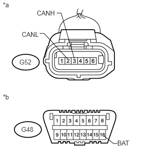
47.CHECK FOR SHORT TO B+ IN CAN BUS WIRE (YAW RATE SENSOR ASSEMBLY)
a.
U148667E04
2.229,2.917 2.438,3.083 2.438,3.083 2.521,3.083 false 1.594,1.25 1.313,0.281 1.313,0.281 1.219,0.281 false 1.448,1.26 0.948,0.719 0.948,0.719 0.854,0.719 false 0.417,1.25 0.719,1.427 0.302,0.177 10 false G52 0.458,2.698 0.781,2.875 0.323,0.177 10 false G48 0.063,0.021 0.271,0.198 0.208,0.177 10 false *a 0.063,2 0.271,2.177 0.208,0.177 10 false *b 2.521,2.99 2.958,3.167 0.438,0.177 10 false BAT 0.469,0.656 0.875,0.833 0.406,0.177 10 false CANL 0.792,0.198 1.208,0.375 0.417,0.177 10 false CANH

Disconnect the G52 yaw rate sensor assembly connector.


b.

Measure the resistance according to the value(s) in the table below.

Standard Resistance:
Tester Connection Switch Condition Specified Condition
G52-3 (CANH) - G48-16 (BAT) Engine switch off 6 kΩ or higher
G52-2 (CANL) - G48-16 (BAT) Engine switch off 6 kΩ or higher


Text in Illustration
*a Front view of wire harness connector
(to Yaw Rate Sensor Assembly)
*b Front view of DLC3


OK

NG

REPAIR OR REPLACE CAN BRANCH WIRE CONNECTED TO YAW RATE SENSOR ASSEMBLY (CANH, CANL)

48.CONNECT CONNECTOR
a.

Reconnect the G100 No. 2 junction connector.


NEXT
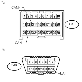
49.CHECK FOR SHORT TO B+ IN CAN BUS WIRE (CENTER AIRBAG SENSOR ASSEMBLY)
a.
U148679E02
2.229,2.917 2.438,3.083 2.438,3.083 2.521,3.083 false 1.188,1.417 1.094,1.802 1.094,1.802 1,1.802 false 1.333,0.969 0.99,0.313 0.99,0.313 0.906,0.313 false 2.896,0.927 3.198,1.104 0.302,0.177 10 false G1 0.448,2.646 0.771,2.823 0.323,0.177 10 false G48 0.063,0.021 0.271,0.198 0.208,0.177 10 false *a 0.063,2 0.271,2.177 0.208,0.177 10 false *b 2.521,2.99 2.958,3.167 0.438,0.177 10 false BAT 0.479,0.229 0.896,0.406 0.417,0.177 10 false CANH 0.625,1.708 1.021,1.885 0.396,0.177 10 false CANL

Disconnect the G1 center airbag sensor assembly connector.


b.

Measure the resistance according to the value(s) in the table below.

Standard Resistance:
Tester Connection Switch Condition Specified Condition
G1-13 (CANH) - G48-16 (BAT) Engine switch off 6 kΩ or higher
G1-22 (CANL) - G48-16 (BAT) Engine switch off 6 kΩ or higher


Text in Illustration
*a Front view of wire harness connector
(to Center Airbag Sensor Assembly)
*b Front view of DLC3


OK

NG

REPAIR OR REPLACE CAN BRANCH WIRE CONNECTED TO CENTER AIRBAG SENSOR ASSEMBLY (CANH, CANL)

50.CONNECT CONNECTOR
a.

Reconnect the G100 No. 2 junction connector.


NEXT
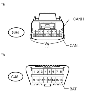
51.CHECK FOR SHORT TO B+ IN CAN BUS WIRE (NO. 3 JUNCTION CONNECTOR - NO. 2 JUNCTION CONNECTOR)
a.
U148984E01
2.206,2.959 2.344,3.208 2.344,3.208 2.484,3.208 false 2.2,1.291 2.404,1.649 2.404,1.649 2.502,1.649 false 2.627,0.682 2.512,0.682 2.512,0.682 2.2,1.103 false 0.045,0.06 0.282,0.297 0.237,0.237 10 *a 0.045,1.892 0.282,2.129 0.237,0.237 10 *b 2.649,0.605 3.069,0.747 0.420,0.142 10 CANH 2.519,1.564 2.943,1.706 0.424,0.142 10 CANL 2.519,3.14 2.943,3.282 0.424,0.142 10 BAT 0.402,2.702 0.684,2.840 0.282,0.138 10 G48 0.427,1.094 0.708,1.232 0.281,0.138 10 G94

Disconnect the G94 No. 3 junction connector.


b.

Measure the resistance according to the value(s) in the table below.

Standard Resistance:
Tester Connection Switch Condition Specified Condition
G94-1 (CANH) - G48-16 (BAT) Engine switch off 6 kΩ or higher
G94-12 (CANL) - G48-16 (BAT) Engine switch off 6 kΩ or higher


Text in Illustration
*a Rear view of wire harness connector
(to No. 3 Junction Connector)
*b Front view of DLC3


OK

52.CHECK FOR SHORT TO B+ IN CAN BUS WIRE (NO. 3 JUNCTION CONNECTOR - MAIN BODY ECU)

NG

REPAIR OR REPLACE CAN MAIN WIRE OR CONNECTOR (NO. 3 JUNCTION CONNECTOR - NO. 2 JUNCTION CONNECTOR)

52.CHECK FOR SHORT TO B+ IN CAN BUS WIRE (NO. 3 JUNCTION CONNECTOR - MAIN BODY ECU)
a.
U148985E01
2.206,2.959 2.344,3.208 2.344,3.208 2.484,3.208 false 2.021,1.291 2.3,1.649 2.3,1.649 2.398,1.649 false 2.523,0.682 2.408,0.682 2.408,0.682 2.021,1.103 false 0.045,0.06 0.282,0.297 0.237,0.237 10 *a 0.045,1.892 0.282,2.129 0.237,0.237 10 *b 2.545,0.605 2.964,0.747 0.420,0.142 10 CANH 2.415,1.564 2.839,1.706 0.424,0.142 10 CANL 2.519,3.14 2.943,3.282 0.424,0.142 10 BAT 0.402,2.702 0.684,2.840 0.282,0.138 10 G48 0.427,1.094 0.708,1.232 0.281,0.138 10 G94

Measure the resistance according to the value(s) in the table below.

Standard Resistance:
Tester Connection Switch Condition Specified Condition
G94-3 (CANH) - G48-16 (BAT) Engine switch off 6 kΩ or higher
G94-14 (CANL) - G48-16 (BAT) Engine switch off 6 kΩ or higher


Text in Illustration
*a Rear view of wire harness connector
(to No. 3 Junction Connector)
*b Front view of DLC3


OK

53.CHECK FOR SHORT TO B+ IN CAN BUS WIRE (NO. 3 JUNCTION CONNECTOR - NO. 5 JUNCTION CONNECTOR OR COMBINATION METER ASSEMBLY)

NG

54.CONNECT CONNECTOR
53.CHECK FOR SHORT TO B+ IN CAN BUS WIRE (NO. 3 JUNCTION CONNECTOR - NO. 5 JUNCTION CONNECTOR OR COMBINATION METER ASSEMBLY)
a.
U149007E01
2.206,2.959 2.344,3.208 2.344,3.208 2.484,3.208 false 2.125,1.291 2.404,1.649 2.404,1.649 2.502,1.649 false 2.627,0.682 2.512,0.682 2.512,0.682 2.125,1.103 false 0.045,0.06 0.282,0.297 0.237,0.237 10 *a 0.045,1.892 0.282,2.129 0.237,0.237 10 *b 2.649,0.605 3.218,0.747 0.569,0.142 10 CANH*B 2.321,0.376 2.207,0.376 2.207,0.376 1.735,1.095 false 2.343,0.299 2.912,0.441 0.569,0.142 10 CANH*A 2.519,1.564 3.069,1.706 0.550,0.142 10 CANL*B 1.735,1.296 2.06,1.896 2.06,1.896 2.157,1.896 false 2.175,1.81 2.725,1.952 0.550,0.142 10 CANL*A 2.519,3.14 2.943,3.282 0.424,0.142 10 BAT 0.402,2.702 0.684,2.840 0.282,0.138 10 G48 0.427,1.094 0.708,1.232 0.281,0.138 10 G94

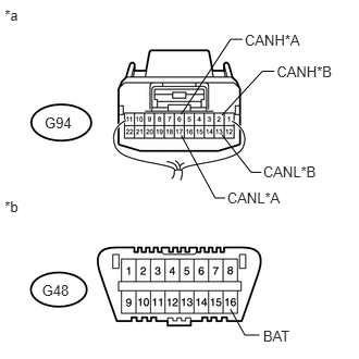
Measure the resistance according to the value(s) in the table below.

Standard Resistance:
for 1GR-FE, 1KD-FTV, 1GD-FTV
Tester Connection Switch Condition Specified Condition
G94-6 (CANH) - G48-16 (BAT) Engine switch off 6 kΩ or higher
G94-17 (CANL) - G48-16 (BAT) Engine switch off 6 kΩ or higher

for 2TR-FE
Tester Connection Switch Condition Specified Condition
G94-2 (CANH) - G48-16 (BAT) Engine switch off 6 kΩ or higher
G94-13 (CANL) - G48-16 (BAT) Engine switch off 6 kΩ or higher


Text in Illustration
*A for 1GR-FE, 1KD-FTV, 1GD-FTV
*B for 2TR-FE
*a Rear view of wire harness connector
(to No. 3 Junction Connector)
*b Front view of DLC3

Result
Result Proceed to
OK A
NG (for 2TR-FE) B
NG (for 1GR-FE, 1KD-FTV, 1GD-FTV) C


A

REPLACE NO. 3 JUNCTION CONNECTOR

B

56.CONNECT CONNECTOR

C

58.CONNECT CONNECTOR
54.CONNECT CONNECTOR
a.

Reconnect the G94 No. 3 junction connector.


NEXT
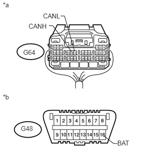
55.CHECK FOR SHORT TO B+ IN CAN BUS WIRE (MAIN BODY ECU)
a.
U148664E03
2.229,2.917 2.438,3.083 2.438,3.083 2.521,3.083 false 1.604,1.104 1.385,0.344 1.385,0.344 1.302,0.344 false 1.542,1.115 1.135,0.552 1.135,0.552 1.052,0.552 false 0.5,1.042 0.844,1.219 0.344,0.177 10 false G64 0.448,2.677 0.771,2.854 0.323,0.177 10 false G48 0.063,0.021 0.271,0.198 0.208,0.177 10 false *a 0.063,2 0.271,2.177 0.208,0.177 10 false *b 2.521,2.99 2.958,3.167 0.438,0.177 10 false BAT 0.615,0.479 1.042,0.656 0.427,0.177 10 false CANH 0.927,0.26 1.323,0.438 0.396,0.177 10 false CANL

Disconnect the G64 main body ECU (multiplex network body ECU) connector.


b.

Measure the resistance according to the value(s) in the table below.

Standard Resistance:
Tester Connection Switch Condition Specified Condition
G64-14 (CANH) - G48-16 (BAT) Engine switch off 6 kΩ or higher
G64-13 (CANL) - G48-16 (BAT) Engine switch off 6 kΩ or higher


Text in Illustration
*a Rear view of wire harness connector
(to Main Body ECU [Multiplex Network Body ECU])
*b Front view of DLC3


OK

REPLACE MAIN BODY ECU (MULTIPLEX NETWORK BODY ECU)

NG

REPAIR OR REPLACE CAN BRANCH WIRE CONNECTED TO MAIN BODY ECU (CANH, CANL)

56.CONNECT CONNECTOR
a.

Reconnect the G94 No. 3 junction connector.


NEXT
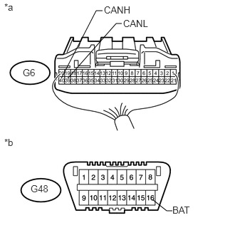
57.CHECK FOR SHORT TO B+ IN CAN BUS WIRE (COMBINATION METER ASSEMBLY)
a.
U148676E04
2.229,2.917 2.438,3.083 2.438,3.083 2.521,3.083 false 0.896,1.146 1.406,0.156 1.406,0.156 1.5,0.156 false 0.99,1.146 1.698,0.344 1.698,0.344 1.781,0.344 false 0.333,0.979 0.625,1.156 0.292,0.177 10 false G6 0.448,2.677 0.771,2.854 0.323,0.177 10 false G48 0.063,0.021 0.271,0.198 0.208,0.177 10 false *a 0.063,2 0.271,2.177 0.208,0.177 10 false *b 2.521,2.99 2.958,3.167 0.438,0.177 10 false BAT 1.802,0.26 2.219,0.438 0.417,0.177 10 false CANL 1.521,0.063 1.99,0.24 0.469,0.177 10 false CANH

Disconnect the G6 combination meter assembly connector.


b.

Measure the resistance according to the value(s) in the table below.

Standard Resistance:
Tester Connection Switch Condition Specified Condition
G6-40 (CANH) - G48-16 (BAT) Engine switch off 6 kΩ or higher
G6-39 (CANL) - G48-16 (BAT) Engine switch off 6 kΩ or higher


Text in Illustration
*a Rear view of wire harness connector
(to Combination Meter Assembly)
*b Front view of DLC3


OK

REPLACE COMBINATION METER ASSEMBLY

NG

REPAIR OR REPLACE CAN MAIN WIRE CONNECTED TO COMBINATION METER ASSEMBLY (CANH, CANL)

58.CONNECT CONNECTOR
a.

Reconnect the G94 No. 3 junction connector.


NEXT
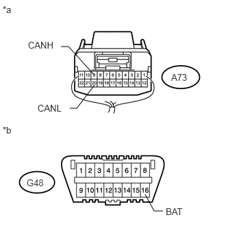
59.CHECK FOR SHORT TO B+ IN CAN BUS WIRE (NO. 5 JUNCTION CONNECTOR - NO. 3 JUNCTION CONNECTOR)
a.
U148986E02
2.208,2.958 2.344,3.208 2.344,3.208 2.479,3.208 false 1.438,1.292 1.167,1.646 1.167,1.646 1.063,1.646 false 0.927,0.708 1.042,0.708 1.042,0.708 1.427,1.135 false 0.042,0.063 0.281,0.302 0.24,0.24 10 false *a 0.042,1.896 0.281,2.135 0.24,0.24 10 false *b 0.427,0.604 0.844,0.75 0.417,0.146 10 false CANH 0.573,1.563 1,1.708 0.427,0.146 10 false CANL 2.521,3.135 2.948,3.281 0.427,0.146 10 false BAT 0.406,2.698 0.792,2.917 0.385,0.219 10 false G48 2.604,1.094 3.021,1.313 0.417,0.219 10 false A73

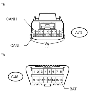
Disconnect the A73 No. 5 junction connector.


b.

Measure the resistance according to the value(s) in the table below.

Standard Resistance:
Tester Connection Switch Condition Specified Condition
A73-9 (CANH) - G48-16 (BAT) Engine switch off 6 kΩ or higher
A73-20 (CANL) - G48-16 (BAT) Engine switch off 6 kΩ or higher


Text in Illustration
*a Rear view of wire harness connector
(to No. 5 Junction Connector)
*b Front view of DLC3


OK

60.CHECK FOR SHORT TO B+ IN CAN BUS WIRE (NO. 5 JUNCTION CONNECTOR - SKID CONTROL ECU)

NG

REPAIR OR REPLACE CAN MAIN WIRE OR CONNECTOR (NO. 5 JUNCTION CONNECTOR - NO. 3 JUNCTION CONNECTOR)

60.CHECK FOR SHORT TO B+ IN CAN BUS WIRE (NO. 5 JUNCTION CONNECTOR - SKID CONTROL ECU)
a.
U148987E01
2.206,2.959 2.344,3.208 2.344,3.208 2.484,3.208 false 1.239,1.291 0.96,1.649 0.96,1.649 0.863,1.649 false 0.738,0.682 0.852,0.682 0.852,0.682 1.239,1.103 false 0.045,0.06 0.282,0.297 0.237,0.237 10 *a 0.045,1.892 0.282,2.129 0.237,0.237 10 *b 0.224,0.605 0.644,0.747 0.420,0.142 10 CANH 0.374,1.564 0.798,1.706 0.424,0.142 10 CANL 2.519,3.14 2.943,3.282 0.424,0.142 10 BAT 0.402,2.702 0.684,2.840 0.282,0.138 10 G48 2.722,1.094 3.002,1.232 0.281,0.138 10 A73

Measure the resistance according to the value(s) in the table below.

Standard Resistance:
Tester Connection Switch Condition Specified Condition
A73-11 (CANH) - G48-16 (BAT) Engine switch off 6 kΩ or higher
A73-22 (CANL) - G48-16 (BAT) Engine switch off 6 kΩ or higher


Text in Illustration
*a Rear view of wire harness connector
(to No. 5 Junction Connector)
*b Front view of DLC3


OK

61.CHECK FOR SHORT TO B+ IN CAN BUS WIRE (NO. 5 JUNCTION CONNECTOR - COMBINATION METER ASSEMBLY)

NG

62.CONNECT CONNECTOR
61.CHECK FOR SHORT TO B+ IN CAN BUS WIRE (NO. 5 JUNCTION CONNECTOR - COMBINATION METER ASSEMBLY)
a.
U148988E01
2.206,2.959 2.344,3.208 2.344,3.208 2.484,3.208 false 1.338,1.291 1.162,1.649 1.162,1.649 1.065,1.649 false 0.939,0.682 1.054,0.682 1.054,0.682 1.338,1.103 false 0.045,0.06 0.282,0.297 0.237,0.237 10 *a 0.045,1.892 0.282,2.129 0.237,0.237 10 *b 0.426,0.605 0.846,0.747 0.420,0.142 10 CANH 0.576,1.564 1.000,1.706 0.424,0.142 10 CANL 2.519,3.14 2.943,3.282 0.424,0.142 10 BAT 0.402,2.702 0.684,2.840 0.282,0.138 10 G48 2.601,1.094 2.882,1.232 0.281,0.138 10 A73

Measure the resistance according to the value(s) in the table below.

Standard Resistance:
Tester Connection Switch Condition Specified Condition
A73-10 (CANH) - G48-16 (BAT) Engine switch off 6 kΩ or higher
A73-21 (CANL) - G48-16 (BAT) Engine switch off 6 kΩ or higher


Text in Illustration
*a Rear view of wire harness connector
(to No. 5 Junction Connector)
*b Front view of DLC3


OK

REPLACE NO. 5 JUNCTION CONNECTOR

NG

64.CONNECT CONNECTOR
62.CONNECT CONNECTOR
a.

Reconnect the A73 No. 5 junction connector.


NEXT
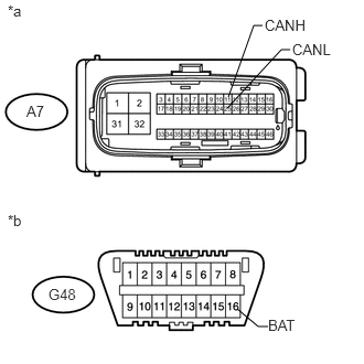
63.CHECK FOR SHORT TO B+ IN CAN BUS WIRE (SKID CONTROL ECU)
a.
U148661E04
2.24,2.917 2.438,3.083 2.438,3.083 2.531,3.083 false 2.156,0.917 2.396,0.24 2.396,0.24 2.479,0.24 false 2.146,1.021 2.656,0.469 2.656,0.469 2.74,0.469 false 0.25,0.969 0.531,1.146 0.281,0.177 10 false A7 0.458,2.698 0.781,2.875 0.323,0.177 10 false G48 0.073,0.021 0.281,0.198 0.208,0.177 10 false *a 0.073,2 0.281,2.177 0.208,0.177 10 false *b 2.531,2.99 2.969,3.167 0.438,0.177 10 false BAT 2.5,0.156 2.938,0.333 0.438,0.177 10 false CANH 2.76,0.385 3.198,0.563 0.438,0.177 10 false CANL

Disconnect the A7 master cylinder solenoid (skid control ECU) connector.


b.

Measure the resistance according to the value(s) in the table below.

Standard Resistance:
Tester Connection Switch Condition Specified Condition
A7-11 (CANH) - G48-16 (BAT) Engine switch off 6 kΩ or higher
A7-25 (CANL) - G48-16 (BAT) Engine switch off 6 kΩ or higher


Text in Illustration
*a Front view of wire harness connector
(to Master Cylinder Solenoid [Skid Control ECU])
*b Front view of DLC3


OK

REPLACE MASTER CYLINDER SOLENOID (SKID CONTROL ECU)

NG

REPAIR OR REPLACE CAN BRANCH WIRE CONNECTED TO SKID CONTROL ECU (CANH, CANL)

64.CONNECT CONNECTOR
a.

Reconnect the A73 No. 5 junction connector.


NEXT
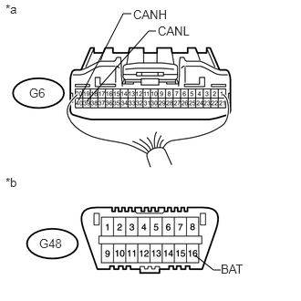
65.CHECK FOR SHORT TO B+ IN CAN BUS WIRE (COMBINATION METER ASSEMBLY)
a.
U148676E05
2.229,2.917 2.438,3.083 2.438,3.083 2.521,3.083 false 0.896,1.146 1.406,0.156 1.406,0.156 1.5,0.156 false 0.99,1.156 1.698,0.354 1.698,0.354 1.781,0.354 false 0.333,0.979 0.625,1.156 0.292,0.177 10 false G6 0.448,2.698 0.771,2.875 0.323,0.177 10 false G48 0.063,0.021 0.271,0.198 0.208,0.177 10 false *a 0.063,2 0.271,2.177 0.208,0.177 10 false *b 2.521,2.99 2.958,3.167 0.438,0.177 10 false BAT 1.802,0.271 2.219,0.448 0.417,0.177 10 false CANL 1.521,0.083 1.99,0.26 0.469,0.177 10 false CANH

Disconnect the G6 combination meter assembly connector.


b.

Measure the resistance according to the value(s) in the table below.

Standard Resistance:
Tester Connection Switch Condition Specified Condition
G6-40 (CANH) - G48-16 (BAT) Engine switch off 6 kΩ or higher
G6-39 (CANL) - G48-16 (BAT) Engine switch off 6 kΩ or higher


Text in Illustration
*a Rear view of wire harness connector
(to Combination Meter Assembly)
*b Front view of DLC3


OK

REPLACE COMBINATION METER ASSEMBLY

NG

REPAIR OR REPLACE CAN MAIN WIRE CONNECTED TO COMBINATION METER ASSEMBLY (CANH, CANL)