VARIABLE GEAR RATIO STEERING STEERING ACTUATOR INSTALLATION
CAUTION / NOTICE / HINT
- HINT:
- ·
Use the same procedure for RHD and LHD vehicles.
·The procedure listed below is for LHD vehicles.
PROCEDURE

 1. HANDLING PRECAUTIONS FOR STEERING ACTUATOR ASSEMBLY
- NOTICE:
- ·
Be careful that the No. 2 seal lip or boot does not turn outward while carrying or installing the steering actuator assembly. If installing a new steering actuator assembly, make sure that the spiral center lock pin is securely inserted.
·Do not use the steering actuator assembly if it has been dropped.
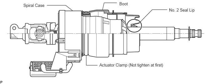 1.563,0.177 2.188,0.177 2.188,0.177 2.417,0.354 false 2.875,1.833 2.875,2.177 false 2.875,2.177 3.25,2.177 false 3.896,0.094 3.469,0.094 false 3.469,0.094 3.417,0.323 false 4.677,0.729 5.073,0.323 false 5.073,0.323 5.573,0.323 false 0.781,0.094 1.563,0.292 0.781,0.198 10 false Spiral Case 3.313,2.083 5.594,2.281 2.281,0.198 10 false Actuator Clamp (Not tighten at first) 3.979,0.042 4.375,0.24 0.396,0.198 10 false Boot 5.635,0.25 6.573,0.438 0.938,0.188 10 false No. 2 Seal Lip
45240J
2.INSTALL STEERING ACTUATOR ASSEMBLY
Make sure that the power steering link assembly is centered.
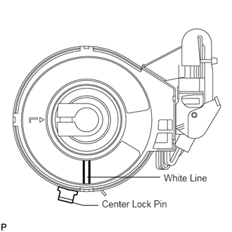
Install the steering actuator assembly.
If installing a new steering actuator assembly:
Install the steering actuator assembly with the white paint on the upper surface of the spiral case facing down.
- NOTICE:
-
Do not pull out the center lock pin.
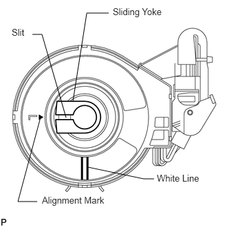
If reinstalling the removed steering actuator assembly:
Slowly turn the spiral case clockwise until it locks.
Turn the spiral case two turns counterclockwise from the lock position.
Align the slit of the sliding yoke with the alignment mark (▲).
Install the steering actuator assembly with the white paint on the upper surface of the spiral case facing down.
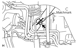
Align the matchmarks on the No. 2 steering intermediate shaft and steering actuator.
- NOTICE:
- ·
Do not fold back the boot part of the steering hole cover or turn it excessively. If it is turned excessively, return it to its original position.
·Do not turn the actuator body and the spiral case.
- HINT:
-
Install the steering actuator from the inside of the vehicle.
Install the bolt.
- Torque:
- 35 N*m (360 kgf*cm, 26 ft.*lbf)
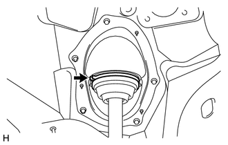
Using needle nose pliers, lock the clamp to the steering column hole cover to install it.
- NOTICE:
-
Be careful when performing the operation as the clamp may not lock if the claws of the clamp are deformed.
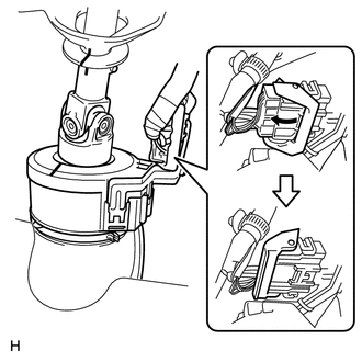
Move the lock in the direction of the arrow and connect the steering actuator connector.
- HINT:
-
When a new actuator is installed, remove the center lock pin.
Connect the connector.
45250
3.INSTALL STEERING COLUMN ASSEMBLY
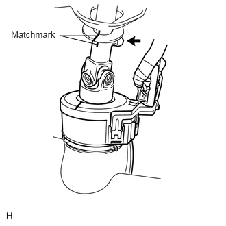
Align the matchmarks on the steering actuator and steering column.
Install the bolt.
- Torque:
- 35 N*m (360 kgf*cm, 26 ft.*lbf)
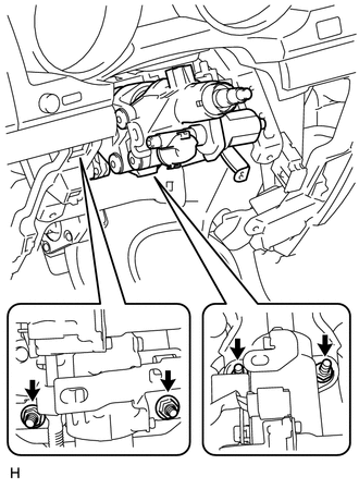
Install the steering column with the 4 nuts.
- Torque:
- 26 N*m (265 kgf*cm, 19 ft.*lbf)
87201F
4.INSTALL NO. 3 AIR DUCT SUB-ASSEMBLY
5.CONNECT WIRE HARNESS PROTECTOR AND WIRE HARNESS
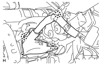
Attach the 3 claws to connect the wire harness protector and wire harness.
73900
6.INSTALL DRIVER SIDE KNEE AIRBAG ASSEMBLY (w/ Driver Side Knee Airbag)
55303B
7.INSTALL LOWER INSTRUMENT PANEL SUB-ASSEMBLY (w/o Driver Side Knee Airbag)
55446A
8.INSTALL NO. 1 SWITCH HOLE BASE
55432D
9.INSTALL LOWER NO. 1 INSTRUMENT PANEL FINISH PANEL
62112
10.INSTALL COWL SIDE TRIM BOARD LH
55606
11.INSTALL NO. 1 INSTRUMENT PANEL UNDER COVER SUB-ASSEMBLY (w/ Floor Under Cover)
67914B
12.INSTALL FRONT DOOR SCUFF PLATE LH
55404C
13.INSTALL INSTRUMENT CLUSTER FINISH PANEL SUB-ASSEMBLY (w/o Multi-information Display)
55404C
14.INSTALL INSTRUMENT CLUSTER FINISH PANEL SUB-ASSEMBLY (w/ Multi-information Display)
55475A
15.INSTALL NO. 2 INSTRUMENT CLUSTER FINISH PANEL GARNISH
55474C
16.INSTALL NO. 1 INSTRUMENT CLUSTER FINISH PANEL GARNISH
55318C
17.INSTALL INSTRUMENT SIDE PANEL LH
55403C
18.INSTALL LOWER INSTRUMENT PANEL PAD SUB-ASSEMBLY LH
55449C
19.INSTALL NO. 2 INSTRUMENT PANEL FINISH PANEL CUSHION
20.INSTALL COMBINATION SWITCH ASSEMBLY WITH SPIRAL CABLE SUB-ASSEMBLY
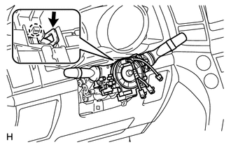
Using pliers, grip the claws of the clamp and install the combination signal switch assembly with spiral cable sub-assembly to the steering column assembly with the clamp.
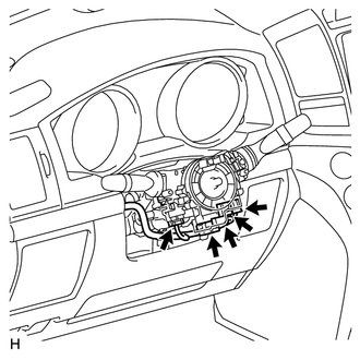
Connect the 5 connectors to the combination switch with spiral cable.
89235A
21.INSTALL TILT AND TELESCOPIC SWITCH
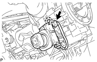
Attach the claw to install the switch.
Connect the switch connector.
45286B
22.INSTALL UPPER STEERING COLUMN COVER
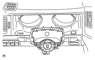
Attach the claw to install the upper steering column cover.
Attach the 4 clips to the instrument cluster finish panel.
23.INSTALL LOWER STEERING COLUMN COVER
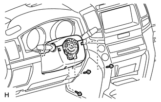
Attach the 2 claws to install the lower steering column cover.
- NOTICE:
-
Do not damage the tilt and telescopic switch.
Install the 3 screws.
- Torque:
- 1.5 N*m (15 kgf*cm, 13 in.*lbf)
45100
24.INSTALL STEERING WHEEL ASSEMBLY
45130
25.INSTALL STEERING PAD
45186
26.INSTALL LOWER NO. 2 STEERING WHEEL COVER
45187
27.INSTALL LOWER NO. 3 STEERING WHEEL COVER
28.CONNECT CABLE TO NEGATIVE BATTERY TERMINAL
- NOTICE:
- ·
Reset the AUTO TILT AWAY function setting to the previous condition by changing the customize parameter (See page General>INTRODUCTION>REPAIR INSTRUCTION>CUSTOMIZE PARAMETERS).
·When disconnecting the cable, some systems need to be initialized after the cable is reconnected (See page General>INTRODUCTION>REPAIR INSTRUCTION>INITIALIZATION).
29.INSPECT SRS WARNING LIGHT
Inspect the SRS warning light (See page Vehicle Interior>SUPPLEMENTAL RESTRAINT SYSTEMS>AIRBAG SYSTEM>DIAGNOSIS SYSTEM).
30. PERFORM VARIABLE GEAR RATIO STEERING SYSTEM CALIBRATION
Perform variable gear ratio steering system calibration (See page Steering>VARIABLE GEAR RATIO STEERING>VARIABLE GEAR RATIO STEERING SYSTEM>CALIBRATION).