HEATING / AIR CONDITIONING CONDENSER INSTALLATION
CAUTION / NOTICE / HINT
- HINT:
- ·
Use the same procedures for LHD and RHD vehicles.
·The procedures listed below are for LHD vehicles.
PROCEDURE

 88474
1.INSTALL COOLER DRYER
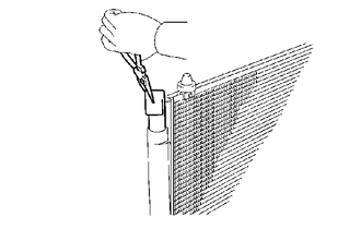
Using pliers, install the cooler dryer.
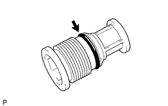
Apply a sufficient amount of compressor oil to the contact surfaces of a new O-ring and the cap.
- Compressor oil:
ND-OIL 8 or equivalent
Install O-ring to the cap.
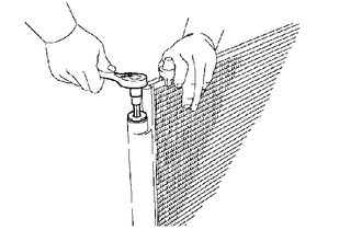
Using a 14 mm socket hexagon wrench, install the cap to the modulator.
- Torque:
- 2.9 N*m (30 kgf*cm, 26 in.*lbf)
88460
2.INSTALL COOLER CONDENSER ASSEMBLY
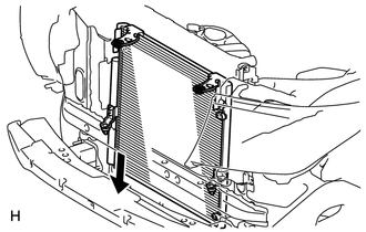
Install the cooler condenser as shown in the illustration.
- HINT:
-
If the cooler condenser assembly is replaced with a new one, add compressor oil to the new cooler condenser assembly.
- Capacity:
40 cc (1.35 fl.oz)
- Compressor oil:
ND-OIL 8 or equivalent
53201
3.INSTALL RADIATOR SUPPORT SUB-ASSEMBLY
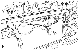
Install the radiator support with the 8 bolts.
- Torque:
- 21.7 N*m (221 kgf*cm, 16 ft.*lbf)
for bolt A
- 9.8 N*m (100 kgf*cm, 7 ft.*lbf)
for bolt B
16400
4.INSTALL RADIATOR ASSEMBLY
53510
5.INSTALL HOOD LOCK ASSEMBLY
53629
6.INSTALL HOOD LOCK CONTROL CABLE COVER
32910
7.CONNECT OIL COOLER ASSEMBLY (w/ Air Cooled Transmission Oil Cooler)
52521
8.INSTALL FRONT BUMPER CENTER UPPER RETAINER
for Standard:
(See page Vehicle Exterior>EXTERIOR PANELS / TRIM>FRONT BUMPER(for Standard)>INSTALLATION)
w/ Winch:
(See page Vehicle Exterior>EXTERIOR PANELS / TRIM>FRONT BUMPER(w/ Winch)>INSTALLATION)
53209B
9.INSTALL HOOD LOCK SUPPORT BRACE SUB-ASSEMBLY
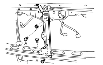
Install the brace with the 3 bolts and nut.
- Torque:
- 21.7 N*m (221 kgf*cm, 16 ft.*lbf)
for bolt A
- 5.5 N*m (56 kgf*cm, 49 in.*lbf)
for nut
53228A
10.INSTALL LOWER NO. 1 RADIATOR MOUNTING BRACKET
88590
11.INSTALL SHROUD BLOWER ASSEMBLY (w/ Rear Air Conditioning System)
86520
12.INSTALL LOW PITCHED HORN ASSEMBLY
86510
13.INSTALL HIGH PITCHED HORN ASSEMBLY
88716A
14.CONNECT COOLER REFRIGERANT LIQUID PIPE A
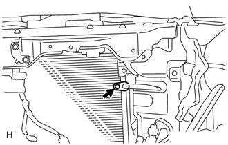
Remove the attached vinyl tape from the hose and the connecting part of the cooler condenser.
Sufficiently apply compressor oil to a new O-ring and the fitting surface of the pipe joint.
- Compressor oil:
ND-OIL 8 or equivalent
Install O-ring on the liquid pipe A.
Connect the liquid pipe A to the cooler condenser with the bolt.
- Torque:
- 5.4 N*m (55 kgf*cm, 48 in.*lbf)
- NOTICE:
- ·
When tightening the bolt, do not allow any tools to contact the pipe.
·When tightening the bolt, hold a part of the pipe near the connector.
88711
15.CONNECT NO. 1 COOLER REFRIGERANT DISCHARGE HOSE
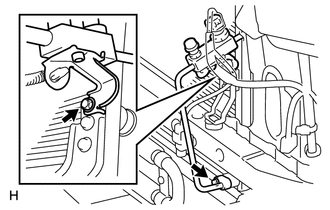
Remove the attached vinyl tape from the pipe and the connecting part of the cooler condenser.
Sufficiently apply compressor oil to a new O-ring and the fitting surface of the hose joint.
- Compressor oil:
ND-OIL 8 or equivalent
Install O-ring on the discharge hose.
Connect the discharge hose to the cooler condenser with the 2 bolts.
- Torque:
- 5.4 N*m (55 kgf*cm, 48 in.*lbf)
- NOTICE:
- ·
When tightening the bolts, do not allow any tools to contact the pipe.
·When tightening the bolts, hold a part of the pipe near the connector.
16.CONNECT CABLE TO NEGATIVE BATTERY TERMINAL
- NOTICE:
-
When disconnecting the cable, some systems need to be initialized after the cable is reconnected (See page General>INTRODUCTION>REPAIR INSTRUCTION>INITIALIZATION).
17.CHARGE REFRIGERANT
18.WARM UP ENGINE
19.CHECK FOR REFRIGERANT GAS LEAK
20.CHECK SRS WARNING LIGHT
52119A
21.INSTALL FRONT BUMPER COVER
for Standard:
(See page Vehicle Exterior>EXTERIOR PANELS / TRIM>FRONT BUMPER(for Standard)>INSTALLATION)
w/ Winch:
(See page Vehicle Exterior>EXTERIOR PANELS / TRIM>FRONT BUMPER(w/ Winch)>INSTALLATION)