1GR-FE ENGINE MECHANICAL ENGINE ASSEMBLY INSTALLATION
PROCEDURE

 12361 1.INSTALL FRONT ENGINE MOUNTING INSULATOR
- HINT:
-
Only perform this procedure when replacement of the front engine mounting insulator is necessary.
Install the 2 front engine mounting insulators with the 2 nuts.
- Torque:
- 72 N*m (734 kgf*cm, 53 ft.*lbf)
2.INSTALL ENGINE HANGER
3.REMOVE ENGINE STAND
Attach an engine sling device and hang the engine with a chain block.
Lift the engine and remove it from the engine stand.
4.INSTALL ENGINE ASSEMBLY
Slowly lower the engine into the engine compartment.
Install the front engine mounting insulator LH and RH to the body with the 2 washers and 2 nuts.
- Torque:
- 87 N*m (887 kgf*cm, 64 ft.*lbf)
5.REMOVE ENGINE HANGER
13405 6.INSTALL FLYWHEEL SUB-ASSEMBLY
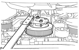
Using SST, hold the crankshaft.
- SST
-
09213-54015 (91651-60855)
09330-00021
Clean the bolts and their installation holes.
Temporarily install the flywheel sub-assembly with 8 new bolts.
Install and tighten the 8 mounting bolts uniformly in several steps.
- Torque:
- 30 N*m (306 kgf*cm, 22 ft.*lbf)
Mark the top of the bolts with paint.
Tighten the 8 bolts 90° in the same sequence.
Check that the paint marks are now at a 90° angle to the top.
31250 7.INSTALL CLUTCH DISC ASSEMBLY
31210 8.INSTALL CLUTCH COVER ASSEMBLY
31210 9.INSPECT AND ADJUST CLUTCH COVER ASSEMBLY
12371 10.INSTALL REAR NO. 1 ENGINE MOUNTING INSULATOR
- HINT:
-
Only perform this procedure when replacement of the rear No. 1 engine mounting insulator is necessary.
11.INSTALL MANUAL TRANSMISSION WITH TRANSFER
37140 12.INSTALL FRONT PROPELLER SHAFT ASSEMBLY
37110 13.INSTALL PROPELLER SHAFT ASSEMBLY
23801P 14.CONNECT NO. 1 FUEL PIPE SUB-ASSEMBLY AND NO. 2 FUEL PIPE SUB-ASSEMBLY
Connect the No. 1 fuel pipe sub-assembly and No. 2 fuel pipe sub-assembly.
Click hereEngine / Hybrid System>1GR-FE (FUEL)>FUEL SYSTEM>PRECAUTION
Install the No. 1 fuel pipe clamp.
88320 15.INSTALL COOLER COMPRESSOR ASSEMBLY (w/ Air Conditioning System)
16631B 16.INSTALL IDLER PULLEY BRACKET (w/o Air Conditioning System)
27020 17.INSTALL GENERATOR ASSEMBLY
12395 18.INSTALL ENGINE MOUNTING BRACKET HEAT INSULATOR
Install the engine mounting bracket heat insulator with the 3 bolts.
- Torque:
- 19 N*m (194 kgf*cm, 14 ft.*lbf)
44310 19.CONNECT VANE PUMP ASSEMBLY
Connect the vane pump assembly with the 2 bolts.
- Torque:
- 21 N*m (214 kgf*cm, 15 ft.*lbf)
Connect the connector.
88712 20.CONNECT NO. 1 COOLER REFRIGERANT SUCTION HOSE (w/ Air Conditioning System)
31482 21.CONNECT CLUTCH TUBE
82121 22.CONNECT ENGINE WIRE
Connect the No. 7 engine wire with the bolt.
- Torque:
- 8.4 N*m (86 kgf*cm, 74 in.*lbf)
Connect the ground cable with the bolt to the rear water by-pass joint.
- Torque:
- 8.4 N*m (86 kgf*cm, 74 in.*lbf)
Connect the No. 2 engine wire with the 2 nuts and attach the 2 wire harness clamps.
- Torque:
- 7.6 N*m (77 kgf*cm, 67 in.*lbf)
Connect the connector to the engine room main wire.
Connect the No. 2 engine wire to the fuse block with the bolt.
- Torque:
- 8.4 N*m (86 kgf*cm, 74 in.*lbf)
Attach the 2 claws to install the fuse block cover.
Attach the 2 wire harness clamps.
Connect the 5 connectors.
87246A 23.CONNECT OUTLET HEATER WATER HOSE
Connect the outlet heater water hose to the hose and valve assembly, and slide the hose clamp to secure the hose.
87245A 24.CONNECT INLET HEATER WATER HOSE
Connect the inlet heater water hose to the heater core, and slide the hose clamp to secure the hose.
17104 25.INSTALL EXHAUST MANIFOLD SUB-ASSEMBLY RH
17118 26.INSTALL NO. 1 MANIFOLD STAY
17105 27.INSTALL EXHAUST MANIFOLD SUB-ASSEMBLY LH
17119 28.INSTALL NO. 2 MANIFOLD STAY
53736 29.INSTALL FRONT FENDER APRON SEAL RH
53737B 30.INSTALL FRONT FENDER APRON SEAL LH
17410 31.INSTALL FRONT EXHAUST PIPE ASSEMBLY (for Model Code #J78, #J79 Series)
17410 32.INSTALL FRONT EXHAUST PIPE ASSEMBLY (for Model Code #J71, #J76 Series)
17129 33.INSTALL INTAKE AIR SURGE TANK
17700 34.INSTALL AIR CLEANER ASSEMBLY
Install the air cleaner assembly with the 2 bolts and nut.
- Torque:
- 18 N*m (184 kgf*cm, 13 ft.*lbf)
17801 35.INSTALL AIR CLEANER FILTER ELEMENT SUB-ASSEMBLY
Install the air cleaner filter element sub-assembly.
17705 36.INSTALL AIR CLEANER CAP SUB-ASSEMBLY WITH NO. 1 AIR CLEANER HOSE
16400 37.INSTALL RADIATOR ASSEMBLY
38.CONNECT CABLE TO NEGATIVE BATTERY TERMINAL
39.ADD ENGINE COOLANT
40.ADD MANUAL TRANSMISSION OIL
41.ADD ENGINE OIL
42.CHARGE REFRIGERANT (w/ Air Conditioning System)
43.INSPECT FOR FUEL LEAK
44.INSPECT FOR COOLANT LEAK
45.INSPECT FOR OIL LEAK
46.CHECK ENGINE OIL LEVEL
47.INSPECT FOR EXHAUST GAS LEAK
48.CHECK FOR REFRIGERANT LEAK (w/ Air Conditioning System)
49.INSPECT IGNITION TIMING
50.INSPECT ENGINE IDLE SPEED
51.INSPECT CO/HC
53301 52.INSTALL HOOD SUB-ASSEMBLY
Install the hood sub-assembly with the 4 bolts.
- Torque:
- 18 N*m (184 kgf*cm, 13 ft.*lbf)
Connect the washer hose.
53301 53.ADJUST HOOD SUB-ASSEMBLY