METER / GAUGE / DISPLAY METER / GAUGE SYSTEM B150718 Turn Signal Light Circuit Current Below Threshold
DESCRIPTION
When the operation signal of the turn signal switch (headlight dimmer switch assembly) is input, the combination meter assembly operates the turn signal lights on the RH and LH sides in response to switch operation. If there is an open in the front or rear turn signal light circuit, the combination meter assembly outputs B150718.
- HINT:
-
If there is an open in a front turn signal light circuit or rear turn signal light circuit, the turn signal lights on the side with the open circuit will blink faster than usual.
| DTC No. | Detection Item | DTC Detection Condition | Trouble Area | Memory | DTC Output from | Priority | Note |
|---|---|---|---|---|---|---|---|
| B150718 | Turn Signal Light Circuit Current Below Threshold | Diagnosis Condition:
Auxiliary battery voltage is 10 V or more Malfunction Status:
·
Open in front turn signal light circuit ·
Open in side turn signal light circuit |
·
Front turn signal light assembly (w/ Adaptive High Beam System) ·
Front turn signal light LED (w/o Adaptive High Beam System) ·
Front multiplex network door ECU (w/ Blind Spot Monitor System) ·
Outer mirror retractor ·
Side turn signal light assembly ·
Rear combination light cord ·
Rear turn signal light LED |
DTC stored | Combination Meter | A | - |
WIRING DIAGRAM
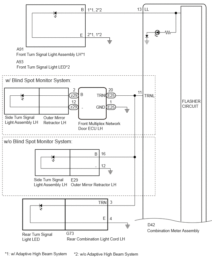
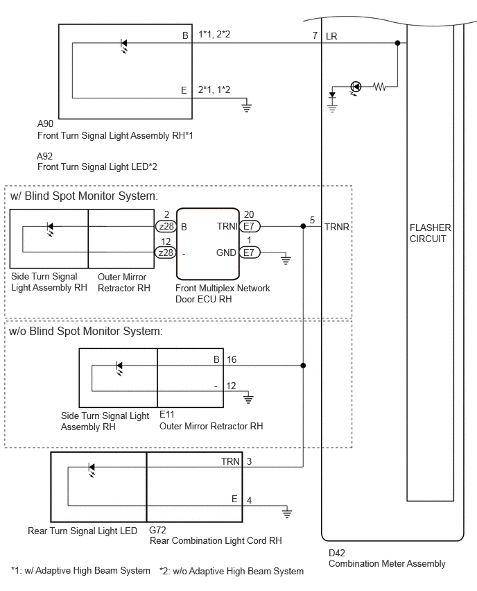
CAUTION / NOTICE / HINT
- NOTICE:
- ·
When replacing the combination meter assembly, always replace it with a new one. If a combination meter assembly which was installed to another vehicle is used, the information stored in it will not match the information from the vehicle and a DTC may be stored.
·If the headlight ECU sub-assembly LH has been replaced, it is necessary to synchronize the vehicle information and initialize the headlight ECU sub-assembly LH.
Click hereVehicle Exterior>LIGHTING (EXT)>LIGHTING SYSTEM>REGISTRATION
PROCEDURE
Inspect the illumination of each turn signal light.
- Result:
Result Proceed to RH side turn signal light or LH side turn signal light does not illuminate. A Rear turn signal light LH and side turn signal light LH does not blink. B Front turn signal light LH does not blink. C Side turn signal light LH does not blink. D Rear turn signal light LH does not blink. E Rear turn signal light RH and side turn signal light RH does not blink. F Front turn signal light RH does not blink. G Side turn signal light RH does not blink. H Rear turn signal light RH does not blink. I
A
B
C
D
E
F
G
H
I
Check vehicle condition.
- Result:
Result Proceed to w/ Blind Spot Monitor System A w/o Blind Spot Monitor System B
A
B
Pre-procedure1
Disconnect the E25 front multiplex network door ECU LH connector.
Disconnect the D42 combination meter assembly connector.
Procedure1
Measure the resistance according to the value(s) in the table below.
- Standard Resistance:
Tester Connection Condition Specified Condition Click Location & Routing(E25,D42)Location & Routingewd_type=routing;type=c,c;code=E25,D42
Click Connector(E25)Body>Front Door Wire LH / Front Door Wire RH>Front Multiplex Network Door ECU LHewd_type=component;type=c;code=E25;pinno=20
Click Connector(D42)Instrument Panel>Instrument Panel Wire>Combination Meter Assemblyewd_type=component;type=c;code=D42;pinno=11
E25-20 (TRNI) - D42-11 (TRNL) Always Below 1 Ω
- Result:
Proceed to OK NG
Post-procedure1
None
OK
NG
Pre-procedure1
Disconnect the E29 outer mirror retractor LH connector.
Disconnect the D42 combination meter assembly connector.
Procedure1
Measure the resistance according to the value(s) in the table below.
- Standard Resistance:
Tester Connection Condition Specified Condition Click Location & Routing(E29,D42)Location & Routingewd_type=routing;type=c,c;code=E29,D42
Click Connector(E29)Body>Front Door Wire LH / Front Door Wire RH>Outer Rear View Mirror Assembly LHewd_type=component;type=c;code=E29;pinno=16
Click Connector(D42)Instrument Panel>Instrument Panel Wire>Combination Meter Assemblyewd_type=component;type=c;code=D42;pinno=11
E29-16 (B) - D42-11 (TRNL) Always Below 1 Ω
- Result:
Proceed to OK NG
Post-procedure1
None
OK
NG
Check vehicle condition.
- Result:
Result Proceed to w/o Adaptive High Beam System A w/ Adaptive High Beam System B
A
B
Click hereVehicle Exterior>LIGHTING (EXT)>FRONT TURN SIGNAL LIGHT ASSEMBLY>INSPECTION
- Result:
Proceed to OK NG
OK
NG
Click hereVehicle Exterior>LIGHTING (EXT)>FRONT TURN SIGNAL LIGHT ASSEMBLY>INSPECTION
- Result:
Proceed to OK NG
OK
NG
Check vehicle condition.
- Result:
Result Proceed to w/ Blind Spot Monitor System A w/o Blind Spot Monitor System B
A
B
Pre-procedure1
Disconnect the E25 front multiplex network door ECU LH connector.
Disconnect the D42 combination meter assembly connector.
Procedure1
Measure the resistance according to the value(s) in the table below.
- Standard Resistance:
Tester Connection Condition Specified Condition Click Location & Routing(E25,D42)Location & Routingewd_type=routing;type=c,c;code=E25,D42
Click Connector(E25)Body>Front Door Wire LH / Front Door Wire RH>Front Multiplex Network Door ECU LHewd_type=component;type=c;code=E25;pinno=20,1
Click Connector(D42)Instrument Panel>Instrument Panel Wire>Combination Meter Assemblyewd_type=component;type=c;code=D42;pinno=11
E25-20 (TRNI) - D42-11 (TRNL) Always Below 1 Ω E25-1 (GND) - Body ground Always Below 1 Ω
- Result:
Proceed to OK NG
Post-procedure1
None
OK
NG
OK
NG
Click hereVehicle Exterior>LIGHTING (EXT)>SIDE TURN SIGNAL LIGHT ASSEMBLY>INSPECTION
- Result:
Proceed to OK NG
OK
NG
OK
NG
Click hereVehicle Exterior>LIGHTING (EXT)>SIDE TURN SIGNAL LIGHT ASSEMBLY>INSPECTION
- Result:
Proceed to OK NG
OK
NG
Click hereVehicle Exterior>LIGHTING (EXT)>REAR COMBINATION LIGHT ASSEMBLY>INSPECTION
- Result:
Proceed to OK NG
OK
NG
Click hereVehicle Exterior>LIGHTING (EXT)>REAR COMBINATION LIGHT ASSEMBLY>INSPECTION
- Result:
Proceed to OK NG
OK
NG
Check vehicle condition.
- Result:
Result Proceed to w/ Blind Spot Monitor System A w/o Blind Spot Monitor System B
A
B
Pre-procedure1
Disconnect the E7 front multiplex network door ECU RH connector.
Disconnect the D42 combination meter assembly connector.
Procedure1
Measure the resistance according to the value(s) in the table below.
- Standard Resistance:
Tester Connection Condition Specified Condition Click Location & Routing(E7,D42)Location & Routingewd_type=routing;type=c,c;code=E7,D42
Click Connector(E7)Body>Front Door Wire LH / Front Door Wire RH>Front Multiplex Network Door ECU RHewd_type=component;type=c;code=E7;pinno=20
Click Connector(D42)Instrument Panel>Instrument Panel Wire>Combination Meter Assemblyewd_type=component;type=c;code=D42;pinno=5
E7-20 (TRNI) - D42-5 (TRNR) Always Below 1 Ω
- Result:
Proceed to OK NG
Post-procedure1
None
OK
NG
Pre-procedure1
Disconnect the E11 outer mirror retractor RH connector.
Disconnect the D42 combination meter assembly connector.
Procedure1
Measure the resistance according to the value(s) in the table below.
- Standard Resistance:
Tester Connection Condition Specified Condition Click Location & Routing(E11,D42)Location & Routingewd_type=routing;type=c,c;code=E11,D42
Click Connector(E11)Body>Front Door Wire LH / Front Door Wire RH>Outer Rear View Mirror Assembly RHewd_type=component;type=c;code=E11;pinno=16
Click Connector(D42)Instrument Panel>Instrument Panel Wire>Combination Meter Assemblyewd_type=component;type=c;code=D42;pinno=5
E11-16 (B) - D42-5 (TRNR) Always Below 1 Ω
- Result:
Proceed to OK NG
Post-procedure1
None
OK
NG
Check vehicle condition.
- Result:
Result Proceed to w/o Adaptive High Beam System A w/ Adaptive High Beam System B
A
B
Click hereVehicle Exterior>LIGHTING (EXT)>FRONT TURN SIGNAL LIGHT ASSEMBLY>INSPECTION
- Result:
Proceed to OK NG
OK
NG
Click hereVehicle Exterior>LIGHTING (EXT)>FRONT TURN SIGNAL LIGHT ASSEMBLY>INSPECTION
- Result:
Proceed to OK NG
OK
NG
Check vehicle condition.
- Result:
Result Proceed to w/ Blind Spot Monitor System A w/o Blind Spot Monitor System B
A
B
Pre-procedure1
Disconnect the E7 front multiplex network door ECU RH connector.
Disconnect the D42 combination meter assembly connector.
Procedure1
Measure the resistance according to the value(s) in the table below.
- Standard Resistance:
Tester Connection Condition Specified Condition Click Location & Routing(E7,D42)Location & Routingewd_type=routing;type=c,c;code=E7,D42
Click Connector(E7)Body>Front Door Wire LH / Front Door Wire RH>Front Multiplex Network Door ECU RHewd_type=component;type=c;code=E7;pinno=20,1
Click Connector(D42)Instrument Panel>Instrument Panel Wire>Combination Meter Assemblyewd_type=component;type=c;code=D42;pinno=5
E7-20 (TRNI) - D42-5 (TRNR) Always Below 1 Ω E7-1 (GND) - Body ground Always Below 1 Ω
- Result:
Proceed to OK NG
Post-procedure1
None
OK
NG
OK
NG
Click hereVehicle Exterior>LIGHTING (EXT)>SIDE TURN SIGNAL LIGHT ASSEMBLY>INSPECTION
- Result:
Proceed to OK NG
OK
NG
OK
NG
Click hereVehicle Exterior>LIGHTING (EXT)>SIDE TURN SIGNAL LIGHT ASSEMBLY>INSPECTION
- Result:
Proceed to OK NG
OK
NG
Click hereVehicle Exterior>LIGHTING (EXT)>REAR COMBINATION LIGHT ASSEMBLY>INSPECTION
- Result:
Proceed to OK NG
OK
NG
Click hereVehicle Exterior>LIGHTING (EXT)>REAR COMBINATION LIGHT ASSEMBLY>INSPECTION
- Result:
Proceed to OK NG
OK
NG