FRONT SUSPENSION FRONT SHOCK ABSORBER REMOVAL
CAUTION / NOTICE / HINT
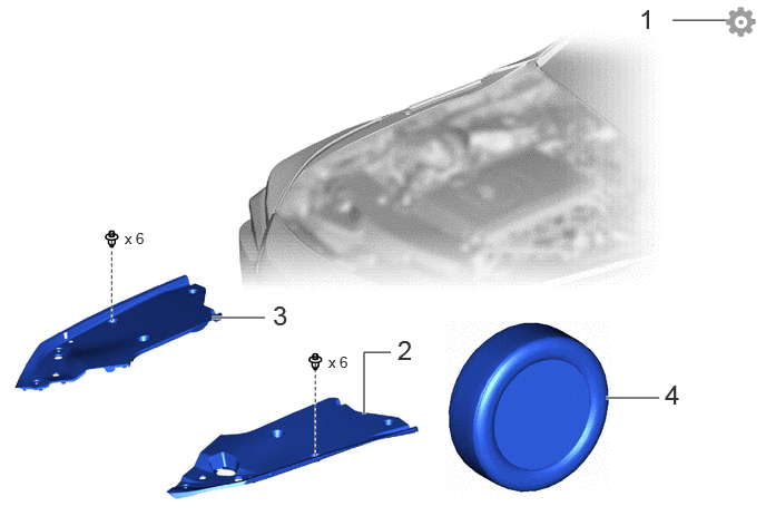
| Procedure | Part Name Code | 
|

|

|
|
|---|---|---|---|---|---|
| 1 | DISABLE BRAKE CONTROL | - | - | - | ( ) |
| 2 | UPPER RADIATOR SUPPORT SEAL | 53292A | - | - | - |
| 3 | RADIATOR COVER PLATE | 53291B | - | - | - |
| 4 | FRONT TIRE | - | - | - | - |
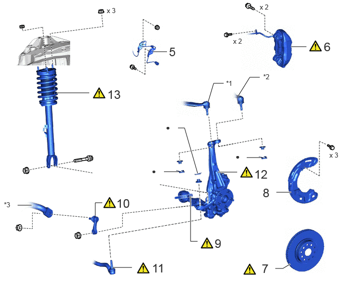
| Procedure | Part Name Code |
|
|
|
|
|---|---|---|---|---|---|
| 5 | SKID CONTROL SENSOR WIRE LH | 89516F | - | - | - |
| 6 | DISC BRAKE CYLINDER ASSEMBLY LH | 47750 | ()
|
- | - |
| 7 | FRONT DISC | 43512 | ()
|
- | - |
| 8 | FRONT DISC BRAKE DUST COVER LH | 47782 | - | - | - |
| 9 | FRONT LOWER SUSPENSION ARM ASSEMBLY LH | 48640 | ()
|
- | - |
| 10 | FRONT STABILIZER LINK ASSEMBLY LH | 48810 | ()
|
- | - |
| 11 | TIE ROD ASSEMBLY LH | 45470 | ()
|
- | - |
| 12 | STEERING KNUCKLE LH | 43212 | ()
|
- | - |
| 13 | FRONT SHOCK ABSORBER WITH COIL SPRING | - | ()
|
- | - |
| *1 | FRONT UPPER NO. 1 SUSPENSION ARM ASSEMBLY LH | *2 | FRONT UPPER NO. 2 SUSPENSION ARM ASSEMBLY LH |
| *3 | FRONT STABILIZER BAR | - | - |
| ● | Non-reusable part | - | - |
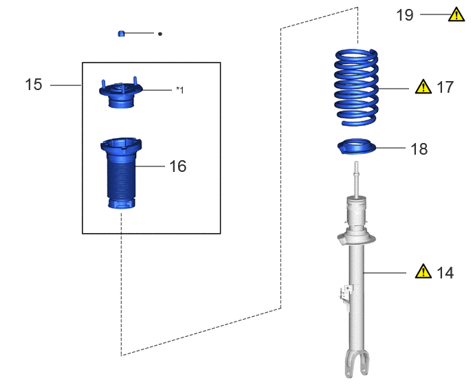
| Procedure | Part Name Code |
|
|
|
|
|---|---|---|---|---|---|
| 14 | FRONT SHOCK ABSORBER ASSEMBLY LH | 48520 | ()
|
- | - |
| 15 | FRONT SUSPENSION SUPPORT ASSEMBLY | 48680 | - | - | - |
| 16 | FRONT UPPER COIL SPRING INSULATOR LH | 48157C | - | - | - |
| 17 | FRONT COIL SPRING LH | 48132 | ()
|
- | - |
| 18 | FRONT LOWER COIL SPRING INSULATOR LH | 48158C | - | - | - |
| 19 | REMOVE SST | - | ()
|
- | - |
| *1 | FRONT SUSPENSION SUPPORT SUB-ASSEMBLY LH | - | - |
| ● | Non-reusable part | - | - |
CAUTION / NOTICE / HINT
The necessary procedures (adjustment, calibration, initialization, or registration) that must be performed after parts are removed, installed, or replaced during the front shock absorber removal/installation are shown below.
- Necessary Procedure After Parts Removed/Installed/Replaced:
Replacement Part or Procedure Necessary Procedures Effects/Inoperative when not Performed Link *: The vehicle height changes because of suspension or tire replacement.
Suspension, tires, etc.* ·Measurement of ultrasonic sensor detection angle
·Ultrasonic sensor detection angle registration
·Parking support brake system
·Advanced park
w/ Advanced Park:
()
w/o Advanced Park:
()
Rear television camera assembly optical axis (Back camera position setting) Parking assist monitor system ( )
·Parking assisr ECU initilization
·Adjust sttering angle
·Rear television camera view adjustment (for Rear camera detection system)
Panoramic view monitor system ( )
Perform headlight ECU sub-assembly LH initialization Automatic headlight beam level control system ( )
Disconnect cable from negative auxiliary battery terminal Memorize steering angle neutral point Parking assist monitor system ( )
Panoramic view monitor system ( )
- NOTICE:
- ·
Immediately after installing the brake pads, the braking performance may be reduced. Always perform a road test in a safe place while paying attention to the surroundings.
·After replacing the front disc brake pads, the brake pedal may feel soft due to clearance between the front disc brake pads and front disc. Depress the brake pedal several times until the brake pedal feels firm.
·When removing or installing the front disc brake cylinder assembly, pushing back the disc brake piston may cause a large clearance between the brake pads and brake disc. When the brake pedal is depressed with a large clearance between the brake pads and the brake disc, DTC C13DB00, C13DC00, C13DD00, C13DE00, C140000 and/or C140A00 related to abnormal brake fluid pressure may be stored. Make sure to clear any DTCs after performing this procedure.
·While the auxiliary battery is connected, even if the ignition switch is off, the brake control system activates when the brake pedal is depressed or any door courtesy switch turns on. Therefore, when servicing the brake system components, do not operate the brake pedal or open/close the doors while the auxiliary battery is connected.
- HINT:
-
When the cable is disconnected/reconnected to the auxiliary battery terminal, systems temporarily stop operating. However, each system has a function that completes learning the first time the system is used.
- ·
Learning completes when vehicle is driven
Effect/Inoperative Function When Necessary Procedures are not Performed Necessary Procedures Link Lane tracing assist system Drive the vehicle straight ahead at 35 km/h (22 mph) or more for 5 seconds or more. ( )
Pre-collision system Adaptive high beam system
·Learning completes when vehicle is operated normally
Effect/Inoperative Function When Necessary Procedures are not Performed Necessary Procedures Link Air conditioning system After the ignition switch is turned to ON, theservo motor and expansion valve standardposition is recognized. -
·Use the same procedure for the RH and LH sides.
·The procedure listed below is for the LH side.
·SST used when removing/installing the coil spring are shown as follows.
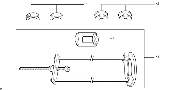 0.677,1.24 6.115,3.719 5.438,2.479 1.313,0.542 1.313,0.188 1.313,0.188 3.563,0.188 true 2.396,0.542 2.396,0.198 true 4.167,1.646 4.594,1.646 true 5.323,0.458 5.323,0.167 true 4.292,0.448 4.292,0.177 4.292,0.177 6.542,0.177 true 6.115,2.427 6.531,2.427 true 3.625,0.083 3.938,0.281 0.313,0.198 10 false *1 6.604,2.333 6.917,2.531 0.313,0.198 10 false *4 4.677,1.552 4.99,1.75 0.313,0.198 10 false *3 6.604,0.083 6.917,0.281 0.313,0.198 10 false *2
*1 SST(09727-58100) *2 SST(09727-58110) *3 SST(09727-58020) *4 SST(09727-58010)
PROCEDURE

 1. DISABLE BRAKE CONTROL
|
|
Click here()
|
53292A
2.REMOVE UPPER RADIATOR SUPPORT SEAL
53291B
3.REMOVE RADIATOR COVER PLATE
4.REMOVE FRONT TIRE
89516F
5.DISCONNECT FRONT SKID CONTROL SENSOR WIRE LH
47750
6.DISCONNECT DISC BRAKE CYLINDER ASSEMBLY LH
|
|
Click here()
|
43512
7.REMOVE FRONT DISC
|
|
Click here()
|
47782
8.REMOVE FRONT DISC BRAKE DUST COVER LH
48640
9.LOOSEN FRONT LOWER SUSPENSION ARM ASSEMBLY LH
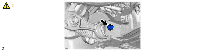
Loosen the installation bolt of the front suspension lower arm assembly LH.
- HINT:
-
Only loosen the bolt. There is no need to remove it.
48810
10.REMOVE FRONT STABILIZER LINK ASSEMBLY LH
|
|
Click here()
|
45470
11.DISCONNECT TIE ROD ASSEMBLY LH
|
|
()
|
43212
12.DISCONNECT STEERING KNUCKLE LH
|
|
Click here()
|
13.REMOVE FRONT SHOCK ABSORBER WITH COIL SPRING
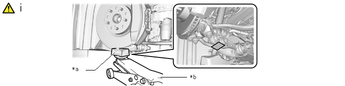
| *a | Wooden Block | *b | Jack |

|
Jack Hold Position | - | - |
Support the front axle assembly LH using a jack and wooden block.
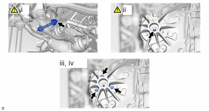
Remove the bolt and nut.
- NOTICE:
- ·
Because the nut has its own stopper, do not turn the nut. Loosen the bolt with the nut secured.
·Do not remove the bolt.
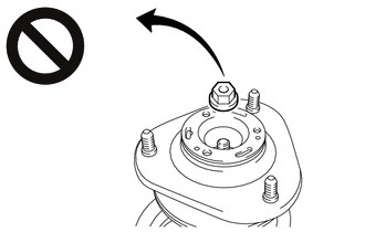
Loosen the lock nut.
- CAUTION:
-
- ·
Only loosen the lock nut, do not remove it.
·If the lock nut is removed with the front coil spring under tension, components of the front shock absorber LH with coil spring may fly off.
- NOTICE:
-
If the front shock absorber LH with coil spring will not be disassembled, do not loosen the lock nut.
Remove the 3 nuts from the front shock absorber with coil spring (upper side).
Slowly lower the jack and remove the front shock absorber with coil spring.
48520
14.REMOVE FRONT SHOCK ABSORBER ASSEMBLY LH
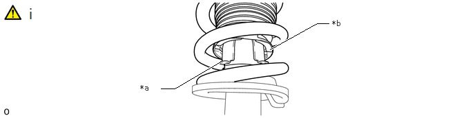
| *a | Front Shock Absorber Assembly LH Claw | *b | End of Front Upper Coil Spring Insulator LH |
Detach the claw and Fold back the front upper coil spring insulator LH.
- NOTICE:
- ·
Check the connection of the front coil spring upper insulator LH and the 3 claws of the front shock absorber assembly LH are completely detached.
·Disconnect the front coil spring upper insulator LH without causing excessive deformation to its bellows.
·Keep the front coil spring upper insulator LH free of oil and grease.
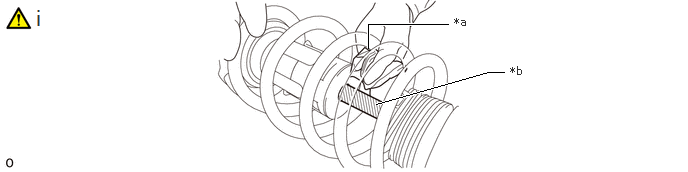
| *a | Cloth, etc. | *b | Shock Rod |
Using a piece of cloth, etc., clean the shock rod and remove any foreign matter and oil.
- NOTICE:
-
Thoroughly clean the shock rod to prevent damage to the shock rod due to contact of foreign matter.
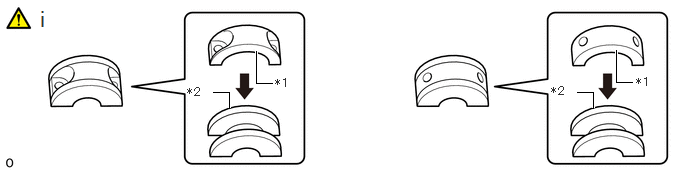
| *1 | SST(09727-58100) | *2 | SST(09727-58110) |
Attach SST (09727-58110) to SST (09727-58100).
- SST
- 09727-58100
09727-58110
- NOTICE:
-
Check that there are no cracks or damage in SST (09727-58110) that could prevent it from securing the shock rod of the front shock absorber assembly LH.
-
If there are, replace SST (09727-58110) with a new one.
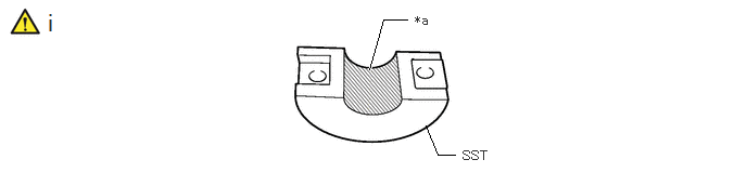
| *a | Installation Surface | - | - |
Clean the surface of SST (09727-58110) to which the front shock absorber assembly LH is installed and remove any foreign matter and oil.
- NOTICE:
-
Thoroughly clean the installation surface to prevent damage to the shock rod due to contact of foreign matter.
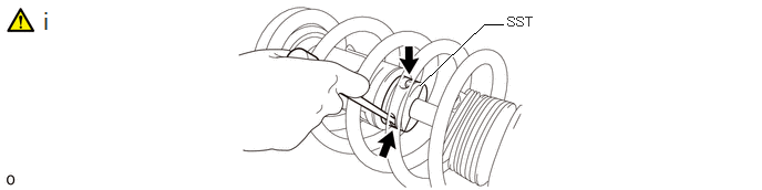
Using a long ball hexagon 5, install SST (09727-58100) and SST (09727-58120) to the shock rod.
- NOTICE:
-
When installing SST (09727-58100) and SST (09727-58120), do not fold back the No. 1 front shock absorber dust cover LH in an improper direction and deform it.
- HINT:
- ·
Install SST (09727-58100) and SST (09727-58110) to the base of the shock rod and check that SST (09727-58100) and SST (09727-58110) are securing the shock rod.
·The front shock absorber assembly LH has a built-in rebound spring and is constructed to constantly contract the shock rod. For this reason, it is difficult to sufficiently contract the coil spring to a level that frees the front suspension support sub-assembly LH using only the coil spring compressor (09727-30022), making it necessary for SST (09727-58100), SST (09727-58110) and a long ball hexagon 5 to be used to ensure a shock rod free length in which work can be performed with a small amount of compression.
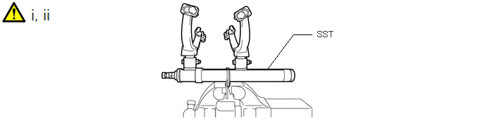
Secure SST in a vise.
- SST
- 09727-30022 (09727-00010, 09727-00022, 09727-00031)
Attach the hooks of each SST arm across the diameter of the coil spring.
- CAUTION:
- ·
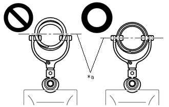 1.563,0.698 1.833,1.479 1.833,1.479 2.104,0.771 false 1.781,1.5 2.094,1.698 0.313,0.198 10 false *a
*a Front Coil Spring Diameter
Do not perform the work without checking to make sure that the claws of the hooks are securely engaged.
·It could cause the hook to slip off and the spring to fly out, which could result in an injury.
·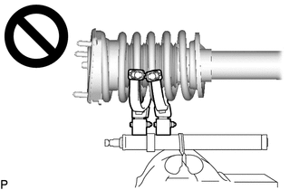
Do not install SST to the front coil spring unless its top and bottom hook distance is set to the widest condition.
·It could cause the hook to slip off and the spring to fly out, which could result in an injury.
·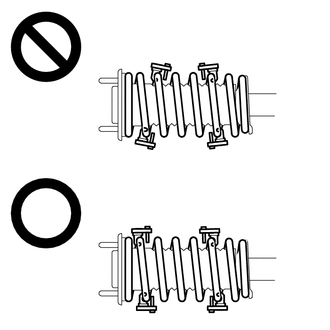
Do not install SST when the distances between the SST arms or the number of coils of the coil spring between the hooks are not the same.
·It could cause the hook to slip off and the spring to fly out, which could result in an injury.
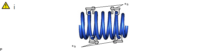
| *a | Stopper Pin | - | - |
Install the stopper pins to the hooks of SST.
- CAUTION:
-
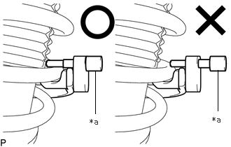 1.417,1.688 1.417,1.052 false 3.24,1.646 3.24,1.042 false 1.333,1.74 1.646,1.896 0.313,0.156 10 false *a 3.156,1.708 3.365,1.865 0.208,0.156 10 false *a
*a Stopper pin
-
Do not perform the work if the stopper pin is not securely installed.
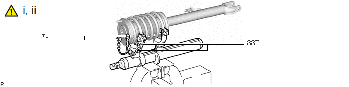
| *a | Vehicle Nut | - | - |
Install SST and 2 vehicle nuts to the upper support as shown in the illustration.
- SST
- 09727-30022 (09727-00090, 09727-00100)
Using SST, compress the coil spring.
- CAUTION:
- ·
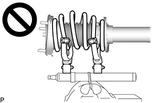
While compressing the spring, if the front coil spring starts to bend into a bow shape, do not continue the work.
·It could cause the hook to slip off and the spring to fly out, which could result in an injury.
·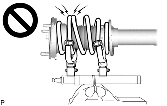
Do not compress the springs so far that the coils of the springs touch each other.
·It could cause the hook to slip off and the spring to fly out, which could result in an injury.
·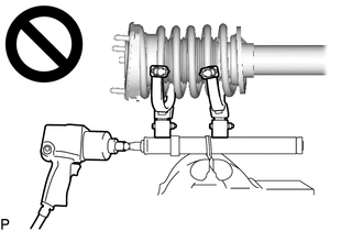
Do not use an impact wrench.
·The threads may be stripped, or the sudden compression may result in slack that causes the hooks to slip off, causing the spring to fly out and possibly resulting in injury.
Install SST as shown in the illustration.
- SST
- 09727-00110
- CAUTION:
- ·
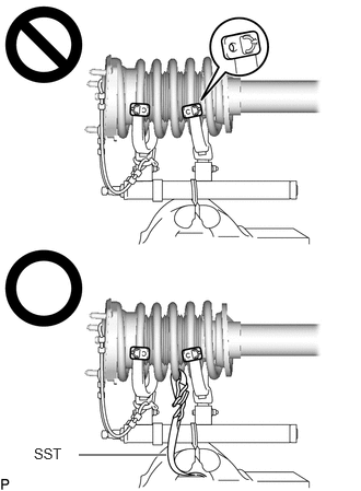 0.75,4.333 1.583,4.333 true 0.323,4.24 0.781,4.438 0.458,0.198 10 false SST
If a stopper pin touches the coil spring while using SST, remove the stopper pin and continue with the procedure.
·If a stopper pin is removed, install a coil spring stopper belt as shown in the illustration.

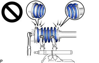
Check that the front coil spring has become free, and remove the front support to front shock absorber lock nut.
- CAUTION:
-
- ·
If the front coil spring has not become free, do not remove the front support to front shock absorber lock nut.
·The spring force will cause the components to be scattered, possibly resulting in injury.
48680
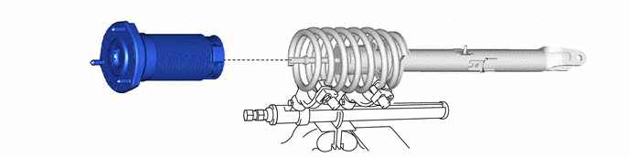
15.REMOVE FRONT SUSPENSION SUPPORT ASSEMBLY
48157C
16.REMOVE FRONT UPPER COIL SPRING INSULATOR LH
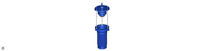
48132
17.REMOVE FRONT COIL SPRING LH

Remove the front coil spring and SST.
- NOTICE:
-
Do not use an impact wrench. It will damage SST.
48158C
18.REMOVE FRONT LOWER COIL SPRING INSULATOR LH

19.REMOVE SST
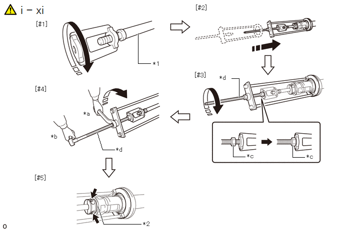
| *1 | Front Shock Absorber Assembly LH | *2 | Shock Absorber Outer Shell |
| *a | Turn | *b | Hold |
| *c | Fixing Nut | *d | Bolt |
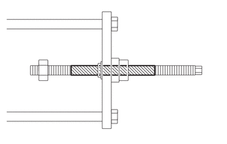
Using SST (09727-58010), remove SST (09727-58100) and SST (09727-58110) from the front shock absorber assembly LH.
- SST
- 09727-58010 (09727-58020)
- NOTICE:
-
 0,0 0,0 false
Application Range
-
Apply molybdenum grease to the bolt (area with diagonal lines) of SST (09727-58010).
Install SST (09727-58020) to the end of the shock rod of the front shock absorber assembly LH.[#1]
Install SST (09727-58010) to the front shock absorber assembly LH.[#2]
- NOTICE:
-
Take due care when installing SST (09727-58010) to ensure the shock rod is not damaged.
Secure the SST (09727-58010) bolt and SST (09727-58020) with the fixing nut.[#3]
After securing the SST (09727-58010) bolt, rotate the nut clockwise.[#4]
- NOTICE:
-
Extend the shock rod until SST (09727-58100) and SST (09727-58110) separate from the shock absorber outer shell.
Using a long ball hexagon 5, remove SST (09727-58100) and SST (09727-58110).[#5]
- NOTICE:
-
If SST (09727-58100) and SST (09727-58110) are removed without using SST (09727-58010), the action of the rebound spring will cause the shock rod to contract suddenly. Therefore, remove SST (09727-58100) and SST (09727-58110) after securing the shock rod with SST (09727-58010).
Using a piece of cloth, etc., clean the shock rod of the front shock absorber assembly LH and remove any foreign matter and oil.
- NOTICE:
-
If the shock rod is expanded/contracted while foreign matter or oil are still present, it may damage the front shock absorber assembly LH or cause oil leaks.
After securing the SST (09727-58010) bolt, rotate the nut counterclockwise.
Check that the shock rod and SST (09727-58020) have become free before releasing the fixing nut and removing SST (09727-58010) from the shock rod.
- NOTICE:
-
Take due care when removing SST (09727-58010) to ensure the shock rod is not damaged.
Remove SST (09727-58020) from the end of the shock rod.
Using a piece of cloth, etc., clean the end of the shock rod threads and remove any foreign matter and oil.