Home › Engine / Hybrid System › FC CONTROL › HYDROGEN RECIRCULATION PUMP
RM37H0E _51 Engine / Hybrid System _095966 FC CONTROL _0466405 HYDROGEN RECIRCULATION PUMP A

FC CONTROL  HYDROGEN RECIRCULATION PUMP  INSTALLATION  


CAUTION / NOTICE / HINT
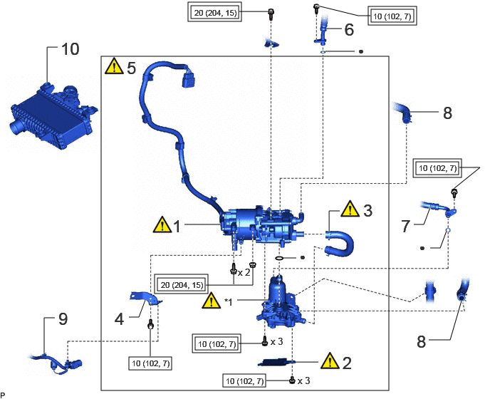
COMPONENTS (INSTALLATION)
A480940N02
1.479,0.823 5.688,5.708 4.208,4.885 2.792,0.083 3.49,0.271 0.698,0.188 2.75,0.031 3.531,0.313 0.781,0.281 5.427,0.135 6.052,0.323 0.625,0.188 5.385,0.094 6.094,0.365 0.708,0.271 6.083,2.365 6.708,2.552 0.625,0.188 6.042,2.323 6.75,2.594 0.708,0.271 2.302,4.063 3,4.25 0.698,0.188 2.26,4.01 3.042,4.292 0.781,0.281 2.813,4.885 3.521,5.156 0.708,0.271 2.854,4.927 3.479,5.115 0.625,0.188 1.885,5.219 2.51,5.406 0.625,0.188 3.26,5.469 3.885,5.656 0.625,0.188 0.688,1.208 0.688,0.688 0.688,0.688 0.844,0.688 true 0.646,5.167 0.646,4.646 0.646,4.646 0.802,4.646 true 5.99,1.635 6.417,1.635 true 6.052,3.281 6.198,3.281 6.198,3.281 6.292,3.031 true 6.292,3.625 6.438,3.625 6.438,3.625 6.531,3.375 true 6.271,4.969 6.583,4.969 6.583,4.969 6.75,4.396 true 4.771,0.417 5,0.417 true 4.76,0.75 5.188,0.75 true 1.885,4.635 2.031,4.635 2.031,4.635 2.125,4.385 true 4.813,3.385 4.813,3.083 4.813,3.083 4.969,3.083 true 4.323,5.292 4.656,5.292 true 2.698,3.281 3.229,3.281 true 3.469,4.385 3.917,4.385 true 4.146,3.771 4.333,3.771 true 3.5,0.167 3.927,0.167 true 4.646,0.083 5.24,0.229 5.24,0.229 5.417,0.229 true 6.646,2.75 7.021,2.448 7.021,2.448 6.719,2.448 true 3.49,5.021 3.823,5.021 true 3.896,5.563 4.229,5.563 true 2.198,4.802 2.198,5.208 true 3.417,4 3.417,4.156 false 3.01,4.167 3.698,4.167 3.698,4.167 3.698,3.906 false 0.885,0.563 1.26,0.917 0.375,0.354 18 false 10 0.854,4.51 1.135,4.865 0.281,0.354 18 false 9 6.479,1.5 6.771,1.854 0.292,0.354 18 false 8 5.865,3.156 6.188,3.51 0.323,0.354 18 false 7 6.094,4.844 6.375,5.198 0.281,0.354 18 false 8 6.135,3.531 6.417,3.885 0.281,0.354 10 false ● 5.042,0.281 5.365,0.635 0.323,0.354 18 false 6 5.24,0.656 5.521,1.01 0.281,0.354 10 false ● 1.854,0.844 2.177,1.198 0.323,0.354 18 false 5 1.677,4.51 2,4.865 0.323,0.354 18 false 4 5.313,2.927 5.635,3.281 0.323,0.354 18 false 3 5.01,5.156 5.333,5.51 0.323,0.354 18 false 2 2.521,3.156 2.844,3.51 0.323,0.354 18 false 1 3.281,4.333 3.604,4.688 0.323,0.354 10 false *1 4.385,3.667 4.667,4.021 0.281,0.354 10 false ● 3.958,4.906 4.281,5.26 0.323,0.354 10 false x 3 4.354,5.479 4.635,5.76 0.281,0.281 10 false x 3 3.479,3.896 3.76,4.177 0.281,0.281 10 false x 2 2.844,0.115 3.563,0.302 0.719,0.188 8 false 20 (204, 15) 5.458,0.167 6.177,0.354 0.719,0.188 8 false 10 (102, 7) 6.125,2.385 6.844,2.573 0.719,0.188 8 false 10 (102, 7) 2.354,4.094 3.073,4.281 0.719,0.188 8 false 20 (204, 15) 1.927,5.24 2.646,5.427 0.719,0.188 8 false 10 (102, 7) 2.896,4.958 3.615,5.146 0.719,0.188 8 false 10 (102, 7) 3.302,5.5 4.021,5.688 0.719,0.188 8 false 10 (102, 7)

Procedure Part Name Code
Z101186

Z101188

Z101187

1 HYDROGEN RECIRCULATION PUMP ASSEMBLY 23C10 (Click here) - -
2 HYDROGEN RECIRCULATION SEPARATOR COVER 23C77 (Click here) - -
3 HYDROGEN PUMP COOLING INLET HOSE 23C21 (Click here) - -
4 WIRE HARNESS CLAMP BRACKET - - - -
5 HYDROGEN RECIRCULATION PUMP ASSEMBLY WITH HYDROGEN RECIRCULATION SEPARATOR ASSEMBLY - (Click here) - -
6 NO. 2 HYDROGEN TUBE 23B12 - - -
7 NO. 3 HYDROGEN TUBE 23B13 - - -
8 WATER HOSE SUB-ASSEMBLY 87209 - - -
9 WIRE HARNESS - - - -
10 INTERCOOLER WITH SENSOR ASSEMBLY 17900 - - -

*1 HYDROGEN RECIRCULATION SEPARATOR ASSEMBLY - -
V111893

Tightening torque for "Major areas involving basic vehicle performance such as moving/turning/stopping": N*m(kgf*cm, ft.*lbf)
V100146

N*m (kgf*cm, ft.*lbf): Specified torque
● Non-reusable part - -

A484095N01
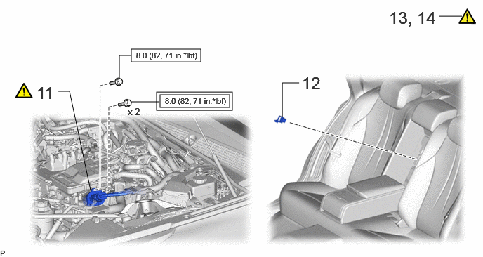
1.948,0.729 2.979,0.917 1.031,0.188 2.323,1.365 3.448,1.635 1.125,0.271 2.375,1.406 3.406,1.594 1.031,0.188 4.188,1.729 4.188,1.229 4.188,1.229 4.438,1.229 false 0.865,1.354 1.031,1.354 1.031,1.354 1.344,2.823 false 6.521,0.24 6.854,0.24 false 1.771,1.156 1.771,0.823 1.771,0.823 1.938,0.823 false 1.948,1.51 2.365,1.51 false 4.479,1.083 5.031,1.438 0.552,0.354 18 false 12 0.542,1.229 1.094,1.583 0.552,0.354 18 false 11 5.771,0.115 6.594,0.427 0.823,0.313 18 false 13, 14 2.021,0.75 3.021,0.938 1,0.188 8 false 8.0 (82, 71 in.*lbf) 1.896,1.573 2.208,1.885 0.313,0.313 10 false x 2 2.448,1.427 3.448,1.615 1,0.188 8 false 8.0 (82, 71 in.*lbf)

Procedure Part Name Code
Z101186

Z101188

Z101187

11 FC CONVERTER POWER OUTLET CABLE (INVERTER WITH CONVERTER ASSEMBLY) G9200A (Click here) - -
12 SERVICE PLUG GRIP G3834 - - -
13 INSPECT FOR HYDROGEN GAS LEAK (for Medium Pressure) - (Click here) - -
14 INSPECT FOR HYDROGEN GAS LEAK (for Low Pressure) - (Click here) - -

V111893

Tightening torque for "Major areas involving basic vehicle performance such as moving/turning/stopping": N*m(kgf*cm, ft.*lbf)
V100146

N*m (kgf*cm, ft.*lbf): Specified torque

A484093N02
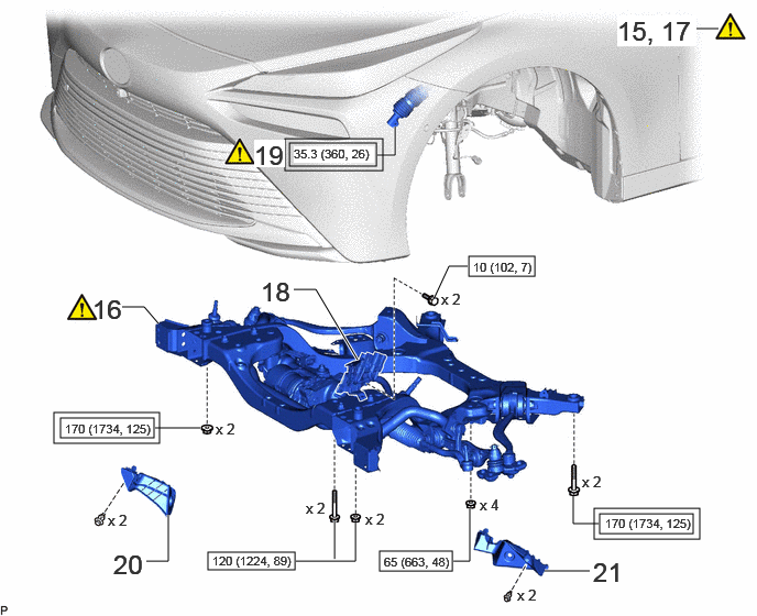
4.438,2.427 5.063,2.615 0.625,0.188 2.74,1.354 3.563,1.573 0.823,0.219 2.698,1.313 3.625,1.615 0.927,0.302 5.677,4.865 6.563,5.052 0.885,0.188 5.625,4.813 6.625,5.104 1,0.292 3.594,5.219 4.281,5.406 0.688,0.188 1.969,5.229 2.792,5.396 0.823,0.167 0.51,3.906 1.51,4.198 1,0.292 0.573,3.958 1.458,4.146 0.885,0.188 3.573,1.469 3.74,1.469 3.74,1.469 3.74,1.198 true 2.781,2.74 2.99,2.74 2.99,2.74 3.385,3.406 true 1.156,2.906 1.365,2.906 1.365,2.906 1.5,3.063 true 1.385,5.313 1.594,5.313 1.594,5.313 1.594,4.875 true 5.156,5.406 5.583,5.406 true 4.427,2.521 4.25,2.521 4.25,2.521 4.115,2.813 true 1.469,4.052 1.896,4.052 true 5.427,4.698 5.427,4.958 5.427,4.958 5.667,4.958 true 4.448,4.813 4.448,5.313 4.448,5.313 4.292,5.313 true 3.365,4.948 3.365,5.313 3.365,5.313 2.802,5.313 true 3.167,4.938 3.167,5.292 true 6.521,0.271 6.802,0.271 true 2.406,1.323 2.698,1.583 0.292,0.26 18 true 19 2.469,2.615 2.823,2.885 0.354,0.271 18 false 18 0.875,2.781 1.208,3.083 0.333,0.302 18 false 16 1.073,5.198 1.448,5.542 0.375,0.344 18 false 20 5.615,5.271 5.969,5.594 0.354,0.323 18 false 21 4.177,2.75 4.458,3.021 0.281,0.271 10 false x 2 5.51,4.479 5.792,4.677 0.281,0.198 10 false x 2 4.542,4.698 4.823,4.917 0.281,0.219 10 false x 4 2.896,4.729 3.115,4.969 0.219,0.24 10 false x 2 3.458,4.833 3.719,5.073 0.26,0.24 10 false x 2 2.042,3.979 2.323,4.208 0.281,0.229 10 false x 2 2.781,1.385 3.542,1.542 0.76,0.156 8 true 35.3 (360, 26) 5.729,4.885 6.594,5.073 0.865,0.188 8 false 170 (1734, 125) 4.479,2.458 5.094,2.635 0.615,0.177 8 false 10 (102, 7) 3.635,5.25 4.313,5.448 0.677,0.198 8 false 65 (663, 48) 2.01,5.24 2.875,5.479 0.865,0.24 8 false 120 (1224, 89) 5.844,0.146 6.594,0.438 0.75,0.292 18 true 15, 17 0.615,3.99 1.479,4.177 0.865,0.188 8 false 170 (1734, 125) 1.021,4.844 1.302,5.073 0.281,0.229 10 false x 2 4.896,5.552 5.177,5.781 0.281,0.229 10 false x 2

Procedure Part Name Code
Z101186

Z101188

Z101187

15 HOLDING BAR - (Click here) - -
16 FRONT FRAME ASSEMBLY 51100G (Click here) - -
17 ENGINE SUPPORT BRIDGE - (Click here) - -
18 WIRE HARNESS CLAMP BRACKET - - - -
19 NO. 2 STEERING INTERMEDIATE SHAFT ASSEMBLY 45260 (Click here) - -
20 FRONT COMPARTMENT SIDE COVER RH 51473D - - -
21 FRONT COMPARTMENT SIDE COVER LH 51474C - - -

V111893

Tightening torque for "Major areas involving basic vehicle performance such as moving/turning/stopping": N*m(kgf*cm, ft.*lbf)
V100146

N*m (kgf*cm, ft.*lbf): Specified torque

A484129N02
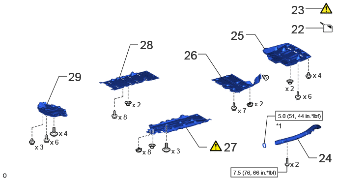
5.844,2.354 6.833,2.552 0.99,0.198 4.896,3.552 5.885,3.75 0.99,0.198 6.719,3.344 6.552,3.344 6.552,3.344 6.302,2.927 false 1,2.198 1.25,1.615 1.25,1.615 1.417,1.615 false 2.531,1.646 2.76,0.948 2.76,0.948 2.927,0.948 false 4.198,1.146 4.365,1.146 4.365,1.146 4.698,1.646 false 5.219,0.729 5.406,0.729 5.406,0.729 5.615,1.042 false 4.385,3.115 4.219,3.115 4.219,3.115 3.938,2.688 false 6.083,3.5 6.083,3.646 6.083,3.646 5.896,3.646 false 5.833,2.458 5.667,2.458 5.667,2.458 5.604,3.031 false 6.479,0.594 6.844,0.594 true 6.479,0.177 6.844,0.177 true 0.74,3.031 0.99,3.219 0.25,0.188 10 false x 3 1.063,2.927 1.313,3.115 0.25,0.188 10 false x 6 1.25,2.74 1.5,2.917 0.25,0.177 10 false x 4 2.51,2.396 2.781,2.583 0.271,0.188 10 false x 8 2.802,2.135 3.135,2.354 0.333,0.219 10 false x 2 3.021,3.135 3.271,3.323 0.25,0.188 10 false x 8 3.635,3.115 3.927,3.354 0.292,0.24 10 false x 3 5.042,2.26 5.271,2.479 0.229,0.219 10 false x 7 5.396,2.115 5.677,2.323 0.281,0.208 10 false x 2 6.052,1.792 6.313,2.021 0.26,0.229 10 false x 2 6.427,1.958 6.75,2.167 0.323,0.208 10 false x 6 6.635,1.51 6.917,1.698 0.281,0.188 10 false x 4 6.156,3.396 6.417,3.656 0.26,0.26 10 false x 2 1.448,1.479 1.844,1.823 0.396,0.344 18 false 29 2.969,0.802 3.396,1.135 0.427,0.333 18 false 28 4.75,2.969 5.135,3.292 0.385,0.323 18 false 27 3.906,1.021 4.313,1.292 0.406,0.271 18 false 26 6.177,0.063 6.563,0.417 0.385,0.354 18 false 23 6.76,3.198 7.104,3.521 0.344,0.323 18 false 24 5.896,2.385 6.917,2.583 1.021,0.198 8 false 5.0 (51, 44 in.*lbf) 4.948,3.583 5.958,3.76 1.01,0.177 8 false 7.5 (76, 66 in.*lbf) 5.854,2.583 6.125,2.771 0.271,0.188 10 false *1 6.177,0.469 6.521,0.792 0.344,0.323 18 false 22 4.896,0.604 5.24,0.927 0.344,0.323 18 false 25

Procedure Part Name Code
Z101186

Z101188

Z101187

22 ADD COOLANT (TOYOTA GENUINE FC STACK COOLANT (Pre-mixed)) - - (Click here) -
23 INSPECT FOR COOLANT (TOYOTA GENUINE FC STACK COOLANT (Pre-mixed)) LEAK - (Click here) - -
24 NO. 3 FC EXHAUST PIPE 17DB3 - - -
25 NO. 1 FLOOR UNDER COVER 58398F - - -
26 REAR FLOOR SIDE MEMBER COVER LH 57628E - - -
27 NO. 2 FLOOR BOARD SUB-ASSEMBLY 58402K (Click here) - -
28 REAR NO. 3 FLOOR BOARD SUB-ASSEMBLY 58403L - - -
29 REAR NO. 4 FLOOR BOARD SUB-ASSEMBLY 58404B - -

*1 HOSE CLAMP - -
V100146

N*m (kgf*cm, ft.*lbf): Specified torque - -

A484131N01
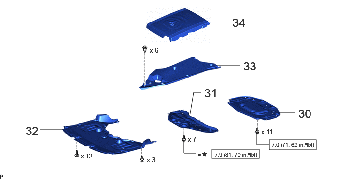
5.708,2.979 6.708,3.188 1,0.208 4.49,3.177 5.5,3.375 1.01,0.198 4.427,0.469 4.844,0.469 false 4.594,1.396 5.094,1.396 false 5.927,2.406 6.26,2.406 false 4.271,1.969 4.104,1.969 4.104,1.969 4.021,2.469 false 0.844,2.76 1.344,2.76 false 4.146,3.26 3.896,3.26 3.896,3.26 3.896,3.01 false 5.698,3.083 5.448,3.083 5.448,3.083 5.448,2.833 false 4.333,1.833 4.688,2.156 0.354,0.323 18 false 31 6.323,2.271 6.667,2.656 0.344,0.385 18 false 30 4.927,0.333 5.271,0.708 0.344,0.375 18 false 34 5.156,1.26 5.542,1.573 0.385,0.313 18 false 33 0.542,2.635 0.906,3.031 0.365,0.396 18 false 32 5.542,2.719 5.938,2.927 0.396,0.208 10 false x 11 3.979,2.885 4.385,3.073 0.406,0.188 10 false x 7 3.115,3.323 3.406,3.521 0.292,0.198 10 false x 3 1.708,3.24 2.031,3.448 0.323,0.208 10 false x 12 3.177,0.99 3.5,1.208 0.323,0.219 10 false x 6 5.76,3.01 6.781,3.208 1.021,0.198 8 false 7.0 (71, 62 in.*lbf) 4.552,3.219 5.51,3.458 0.958,0.24 8 false 7.9 (81, 70 in.*lbf) 4.188,3.198 4.563,3.375 0.375,0.177 10 false ●★

Procedure Part Name Code
Z101186

Z101188

Z101187

30 FRONT COMPARTMENT UNDER COVER ASSEMBLY 51420A - - -
31 FRONT LOWER SUSPENSION MEMBER PROTECTOR 51219 - - -
32 FRONT COMPARTMENT UNDER COVER 51441N - - -
33 UPPER RADIATOR SUPPORT SEAL 53292A - - -
34 FC STACK COVER SUB-ASSEMBLY 1A906 - - -

V100146

N*m (kgf*cm, ft.*lbf): Specified torque ● Non-reusable part
★ Precoated part - -

PROCEDURE

Hide 23C10 1.INSTALL HYDROGEN RECIRCULATION PUMP ASSEMBLY
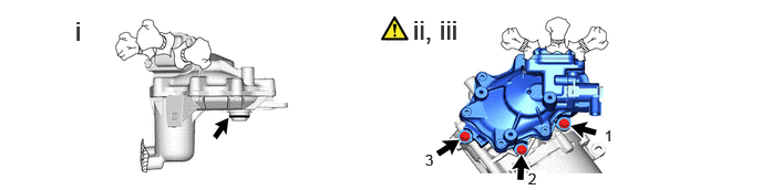
a.
A480941N01
0.708,0.146 0.99,0.5 0.281,0.354 18 false i 3.885,0.135 4.375,0.51 0.49,0.375 18 false ii, iii 5.688,1.198 5.938,1.458 0.25,0.26 10 false 1 4.969,1.604 5.135,1.75 0.167,0.146 10 true 2 4,1.427 4.198,1.615 0.198,0.188 10 false 3

i.

Install the new O-ring from the hydrogen recirculation separator assembly.


ii.

Temporarily install the 3 bolts.


iii.

Install the hydrogen recirculation pump assembly to the hydrogen recirculation separator assembly with the 3 bolts in the order shown in the illustration.

Torque:
10 N*m (102 kgf*cm, 7 ft.*lbf)


Hide 23C77 2.INSTALL HYDROGEN RECIRCULATION SEPARATOR COVER

a.
A480942N01
4.458,0.271 4.667,0.479 0.208,0.208 10 false A 3.365,0.188 3.573,0.396 0.208,0.208 10 false B 3.531,1.344 3.677,1.51 0.146,0.167 10 true C 2.417,0.083 2.667,0.354 0.25,0.271 18 false i

i.

Install the hydrogen recirculation separator cover with the 3 bolts.

Torque:
10 N*m (102 kgf*cm, 7 ft.*lbf)

NOTICE:

Temporarily tighten the bolt (A), and then install the 3 bolts in the order of (B), (C) and (A).


Hide 23C21 3.INSTALL HYDROGEN PUMP COOLING INLET HOSE
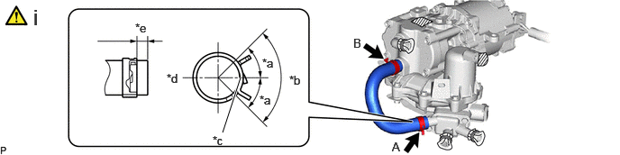
a.
A480943C01
2.573,1.531 2.781,0.896 true 3.031,0.646 3.344,0.802 0.313,0.156 10 false *a 3.344,0.844 3.646,1.052 0.302,0.208 10 false *b 2.458,1.542 2.75,1.698 0.292,0.156 10 false *c 1.927,0.823 2.24,0.979 0.313,0.156 10 false *d 1.563,0.24 1.875,0.396 0.313,0.156 10 false *e 3,1.073 3.313,1.229 0.313,0.156 10 false *a 4.531,1.615 4.771,1.781 0.24,0.167 10 false A 4.083,0.417 4.385,0.625 0.302,0.208 10 false B 0.385,0.052 0.76,0.354 0.375,0.302 18 false i
*a 45° *b 90°
*c Paint Mark *d Top
*e 2 to 5 mm - -


i.

Install the hydrogen pump cooling inlet hose to the hydrogen recirculation pump assembly with hydrogen recirculation separator assembly and slide the 2 clips to secure it.

NOTICE:
·

Make sure to position the clip as shown in the illustration.

·

No designated position for the clip claws B.


Hide 4.INSTALL WIRE HARNESS CLAMP BRACKET

Torque:
10 N*m (102 kgf*cm, 7 ft.*lbf)

Hide 5.INSTALL HYDROGEN RECIRCULATION PUMP ASSEMBLY WITH HYDROGEN RECIRCULATION SEPARATOR ASSEMBLY
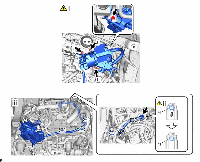
a.
A475885C01
5.813,4.021 6.073,3.875 true 5.813,5.135 6.073,4.99 true 2.448,0.156 2.729,0.51 0.281,0.354 18 false i 5.833,3.583 6.115,3.938 0.281,0.354 18 false ii 0.438,3.552 0.656,3.833 0.219,0.281 18 true iii 5.646,3.979 5.927,4.333 0.281,0.354 10 false *1 5.656,5.104 5.938,5.458 0.281,0.354 10 false *1 3.448,2.781 3.615,2.938 0.167,0.156 10 true 1 2.521,1.573 2.677,1.729 0.156,0.156 10 true 2 3.438,1.438 3.583,1.563 0.146,0.125 10 true 3 4.146,0.177 4.281,0.313 0.135,0.135 10 true 4
*1 Green-colored Lock - -


i.

Install the hydrogen recirculation pump assembly with hydrogen recirculation separator assembly with the 3 bolts and nut in the order shown in the illustration.

Torque:
20 N・m (204 kgf・cm, )


ii.

As shown in the illustration, connect the connector push in the green-colored lock to securely fix it in place.


iii.

Attach the 6 clamps.


Hide 23B12 6.INSTALL NO. 2 HYDROGEN TUBE

Torque:
10 N*m (102 kgf*cm, 7 ft.*lbf)

Hide 23B13 7.INSTALL NO. 3 HYDROGEN TUBE

Torque:
10 N*m (102 kgf*cm, 7 ft.*lbf)

Hide 87209 8.CONNECT WATER HOSE SUB-ASSEMBLY

Hide 9.CONNECT WIRE HARNESS

Hide 17900 10.INSTALL INTERCOOLER WITH SENSOR ASSEMBLY

Hide G9200A 11.CONNECT FC CONVERTER POWER OUTLET CABLE (INVERTER WITH CONVERTER ASSEMBLY)

Z101186

Click here(Click here)

Hide 13.INSPECT FOR HYDROGEN GAS LEAK (for Medium Pressure)

Z101186

Click here(Click here)

Hide 14.INSPECT FOR HYDROGEN GAS LEAK (for Low Pressure)

Z101186

Click here(Click here)

Hide 15.INSTALL HOLDING BAR

Hide 51100G 16.INSTALL FRONT FRAME ASSEMBLY
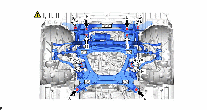
a.
A480960C02
1.49,0.385 2.135,0.688 0.646,0.302 18 true i, ii, iii 2.365,3.344 2.51,3.5 0.146,0.156 10 true A 4.969,3.354 5.115,3.51 0.146,0.156 10 true A 2.969,0.49 3.104,0.667 0.135,0.177 10 true B 4.354,0.51 4.49,0.688 0.135,0.177 10 true B 2.479,0.479 2.604,0.635 0.125,0.156 10 true C 4.833,0.479 4.958,0.635 0.125,0.156 10 true C 2.948,1.531 3.073,1.688 0.125,0.156 10 true D 4.354,1.531 4.479,1.688 0.125,0.156 10 true D 2.417,1.99 2.542,2.146 0.125,0.156 10 true E 2.417,2.354 2.542,2.51 0.125,0.156 10 true E 4.865,2.021 4.99,2.177 0.125,0.156 10 true E 4.885,2.396 5.042,2.552 0.156,0.156 10 true E
V100135

Bolt
V100136

Nut
V100155

Attachments - -


i.

Set the front frame assembly on an engine lifter.

CAUTION:
C323114

·

The front frame assembly is a heavy component. Make sure that it is supported securely.

·

If it is not supported securely, it could fall and result in a serious accident.


NOTICE:

Using height adjustment attachments and plate lift attachments, keep the front frame assembly level.


ii.

Raise the rear suspension member sub-assembly until there is no clearance between the front frame assembly and vehicle body.

NOTICE:

When raising the front frame assembly, be careful not to damage the vehicle body or other components installed to the vehicle.


iii.

Install the front frame assembly with the 4 bolts and 8 nuts.

Torque:
Bolt (A), Nut (C) : 170 N*m (1734 kgf*cm, 125 ft.*lbf)
Bolt (B), Nut (D) : 120 N*m (1224 kgf*cm, 89 ft.*lbf)
Nut (E) : 65 N*m (663 kgf*cm, 48 ft.*lbf)

NOTICE:
·

Perform this procedure with several people supporting the front frame assembly so that it does not tilt or fall.

·

Remove while paying attention to the wire harnesses and steering shaft.


Hide 17.REMOVE ENGINE SUPPORT BRIDGE

Hide 18.CONNECT WIRE HARNESS CLAMP BRACKET

Torque:
10 N*m (102 kgf*cm, 7 ft.*lbf)

Hide 45260 19.CONNECT NO. 2 STEERING INTERMEDIATE SHAFT ASSEMBLY

Z101186

Click here(Click here)

Hide 51473D 20.INSTALL FRONT COMPARTMENT SIDE COVER RH

a.

Use the same procedure as for the LH side.


Hide 51474C 21.INSTALL FRONT COMPARTMENT SIDE COVER LH

Hide 22.ADD COOLANT (TOYOTA GENUINE FC STACK COOLANT (Pre-mixed))

Hide 23.INSPECT FOR COOLANT (TOYOTA GENUINE FC STACK COOLANT (Pre-mixed)) LEAK

Hide 17DB3 24.INSTALL NO. 3 FC EXHAUST PIPE

Hide 58398F 25.INSTALL NO. 1 FLOOR UNDER COVER

Hide 57628E 26.INSTALL REAR FLOOR SIDE MEMBER COVER LH

Hide 58402K 27.INSTALL NO. 2 FLOOR BOARD SUB-ASSEMBLY

Z101186

Click here(Click here)

Hide 58403L 28.INSTALL REAR NO. 3 FLOOR BOARD SUB-ASSEMBLY

Hide 58404B 29.INSTALL REAR NO. 4 FLOOR BOARD SUB-ASSEMBLY

Hide 51420A 30.INSTALL FRONT COMPARTMENT UNDER COVER ASSEMBLY

Hide 51219 31.INSTALL FRONT LOWER SUSPENSION MEMBER PROTECTOR

Hide 51441N 32.INSTALL FRONT COMPARTMENT UNDER COVER

Hide 53292A 33.INSTALL UPPER RADIATOR SUPPORT SEAL

Hide 1A906 34.INSTALL FC STACK COVER SUB-ASSEMBLY