FRONT SUSPENSION FRONT SUSPENSION MEMBER INSTALLATION
CAUTION / NOTICE / HINT
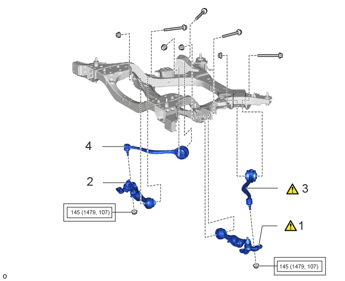
| Procedure | Part Name Code | 
|

|

|
|
|---|---|---|---|---|---|
| 1 | TEMPORARILY TIGHTEN FRONT LOWER SUSPENSION ARM ASSEMBLY LH | 48640 | ( ) |
- | - |
| 2 | TEMPORARILY TIGHTEN FRONT LOWER SUSPENSION ARM ASSEMBLY RH | 48620 | - | - | - |
| 3 | TEMPORARILY TIGHTEN LOWER NO. 2 SUSPENSION ARM ASSEMBLY LH | 48670A | ()
|
- | - |
| 4 | TEMPORARILY TIGHTEN LOWER NO. 2 SUSPENSION ARM ASSEMBLY RH | 48660C | - | - | - |

|
Tightening torque for "Major areas involving basic vehicle performance such as moving/turning/stopping": N*m (kgf*cm, ft.*lbf) | - | - |
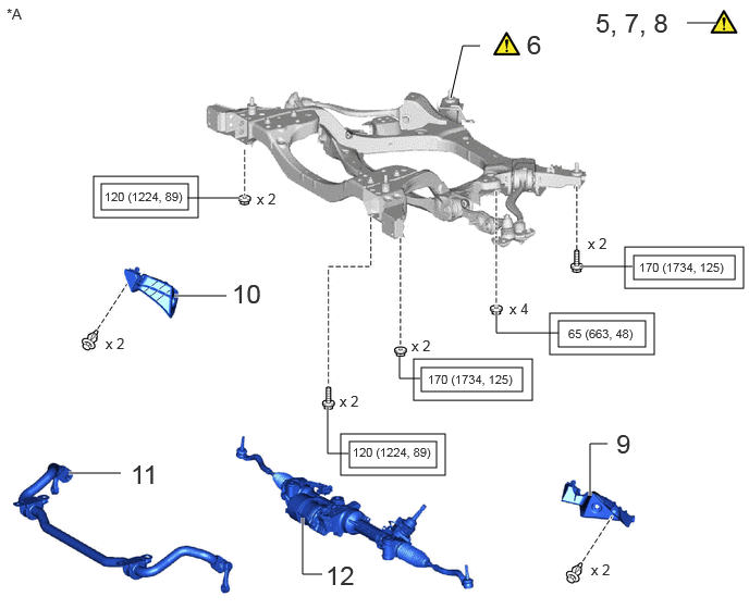
| Procedure | Part Name Code |
|
|
|
|
|---|---|---|---|---|---|
| 5 | REMOVE HOLDING BAR | - | ()
|
- | - |
| 6 | FRONT FRAME ASSEMBLY | 51100G | ()
|
- | - |
| 7 | REMOVE ENGINE SUPPORT BRIDGE | - | ()
|
- | - |
| 8 | REMOVE ENGINE HANGER | - | ()
|
- | - |
| 9 | FRONT COMPARTMENT SIDE COVER LH | 51474C | - | - | - |
| 10 | FRONT COMPARTMENT SIDE COVER RH | 51473D | - | - | - |
| 11 | FRONT STABILIZER BAR | 48811 | - | - | - |
| 12 | RACK AND PINION POWER STEERING GEAR ASSEMBLY | 44250 | - | - | - |
| *A | for LHD | - | - |
|
|
Tightening torque for "Major areas involving basic vehicle performance such as moving/turning/stopping": N*m (kgf*cm, ft.*lbf) | - | - |
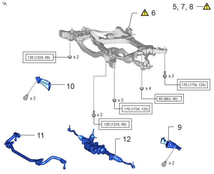
| Procedure | Part Name Code |
|
|
|
|
|---|---|---|---|---|---|
| 5 | REMOVE HOLDING BAR | - | ()
|
- | - |
| 6 | FRONT FRAME ASSEMBLY | 51100G | ()
|
- | - |
| 7 | REMOVE ENGINE SUPPORT BRIDGE | - | ()
|
- | - |
| 8 | REMOVE ENGINE HANGER | - | ()
|
- | - |
| 9 | FRONT COMPARTMENT SIDE COVER LH | 51474C | - | - | - |
| 10 | FRONT COMPARTMENT SIDE COVER RH | 51473D | - | - | - |
| 11 | FRONT STABILIZER BAR | 48811 | - | - | - |
| 12 | RACK AND PINION POWER STEERING GEAR ASSEMBLY | 44250 | - | - | - |
| *A | for RHD | - | - |
|
|
Tightening torque for "Major areas involving basic vehicle performance such as moving/turning/stopping": N*m (kgf*cm, ft.*lbf) | - | - |
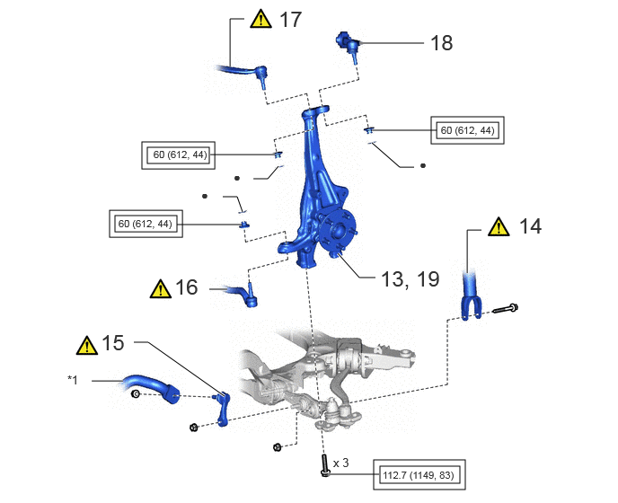
| Procedure | Part Name Code |
|
|
|
|
|---|---|---|---|---|---|
| 13 | TEMPORARILY TIGHTEN STEERING KNUCKLE LH | 52119A | - | - | - |
| 14 | TEMPORARILY TIGHTEN FRONT SHOCK ABSORBER ASSEMBLY LH- | 52029B | ()
|
- | - |
| 15 | TEMPORARILY TIGHTEN FRONT STABILIZER LINK ASSEMBLY LH | 53288B | ()
|
- | - |
| 16 | TIE ROD ASSEMBLY LH | 53287B | ()
|
- | - |
| 17 | FRONT UPPER NO. 1 SUSPENSION ARM ASSEMBLY LH | 51116 | ()
|
- | - |
| 18 | FRONT UPPER NO. 2 SUSPENSION ARM ASSEMBLY LH | 51115 | - | - | - |
| 19 | FULLY TIGHTEN STEERING KNUCKLE LH | 52119A | - | - | - |
| *1 | FRONT STABILIZER BAR | - | - |
|
|
Tightening torque for "Major areas involving basic vehicle performance such as moving/turning/stopping": N*m (kgf*cm, ft.*lbf) | ● | Non-reusable part |
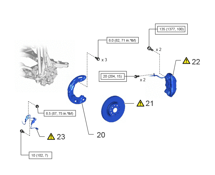
| Procedure | Part Name Code |
|
|
|
|
|---|---|---|---|---|---|
| 20 | FRONT DISC BRAKE DUST COVER LH | 47782 | - | - | - |
| 21 | FRONT DISC LH | 43512 | ()
|
- | - |
| 22 | DISC BRAKE CYLINDER ASSEMBLY LH | 47750 | ()
|
- | - |
| 23 | FRONT SKID CONTROL SENSOR WIRE LH | 89516F | ()
|
- | - |
|
|
Tightening torque for "Major areas involving basic vehicle performance such as moving/turning/stopping": N*m (kgf*cm, ft.*lbf) | 
|
N*m (kgf*cm, ft.*lbf): Specified torque |
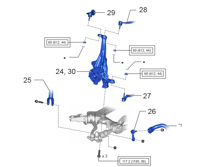
| Procedure | Part Name Code |
|
|
|
|
|---|---|---|---|---|---|
| 24 | TEMPORARILY TIGHTEN STEERING KNUCKLE RH | 43211 | - | - | - |
| 25 | TEMPORARILY TIGHTEN FRONT SHOCK ABSORBER ASSEMBLY RH | 48510 | - | - | - |
| 26 | TEMPORARILY TIGHTEN FRONT STABILIZER LINK ASSEMBLY RH | 48820B | - | - | - |
| 27 | TIE ROD ASSEMBLY RH | 45460 | - | - | - |
| 28 | FRONT UPPER NO. 1 SUSPENSION ARM ASSEMBLY RH | 48610H | - | - | - |
| 29 | FRONT UPPER NO. 2 SUSPENSION ARM ASSEMBLY RH | 48610J | - | - | - |
| 30 | FULLY TIGHTEN STEERING KNUCKLE RH | 43211 | - | - | - |
| *1 | FRONT STABILIZER BAR | - | - |
|
|
Tightening torque for "Major areas involving basic vehicle performance such as moving/turning/stopping": N*m (kgf*cm, ft.*lbf) | ● | Non-reusable part |
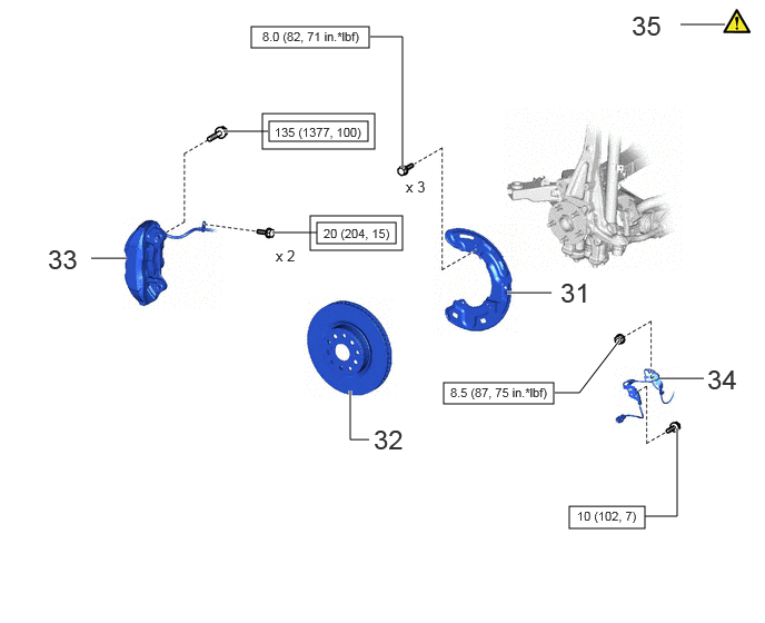
| Procedure | Part Name Code |
|
|
|
|
|---|---|---|---|---|---|
| 31 | FRONT DISC BRAKE DUST COVER RH | 47781 | - | - | - |
| 32 | FRONT DISC | 43512 | - | - | - |
| 33 | DISC BRAKE CYLINDER ASSEMBLY RH | 47750 | - | - | - |
| 34 | FRONT SKID CONTROL SENSOR WIRE RH | 89516E | - | - | - |
| 35 | STABILIZE SUSPENSION | - | ()
|
- | - |
|
|
Tightening torque for "Major areas involving basic vehicle performance such as moving/turning/stopping": N*m (kgf*cm, ft.*lbf) |
|
N*m (kgf*cm, ft.*lbf): Specified torque |
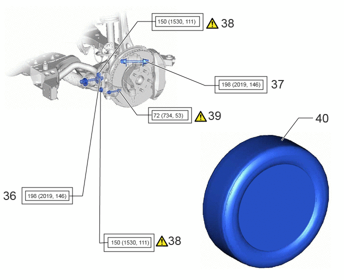
| Procedure | Part Name Code |
|
|
|
|
|---|---|---|---|---|---|
| 36 | FULLY TIGHTEN FRONT LOWER SUSPENSION ARM ASSEMBLY LH | 48640 | - | - | - |
| 37 | FULLY TIGHTEN LOWER NO. 2 SUSPENSION ARM ASSEMBLY LH | 48670A | - | - | - |
| 38 | FULLY TIGHTEN FRONT STABILIZER LINK ASSEMBLY LH | 48810 | ()
|
- | - |
| 39 | FULLY TIGHTEN FRONT SHOCK ABSORBER ASSEMBLY LH | 48520 | ()
|
- | - |
| 40 | FRONT TIRE LH | - | - | - | - |
|
|
Tightening torque for "Major areas involving basic vehicle performance such as moving/turning/stopping": N*m (kgf*cm, ft.*lbf) | - | - |
| Procedure | Part Name Code |
|
|
|
|
|---|---|---|---|---|---|
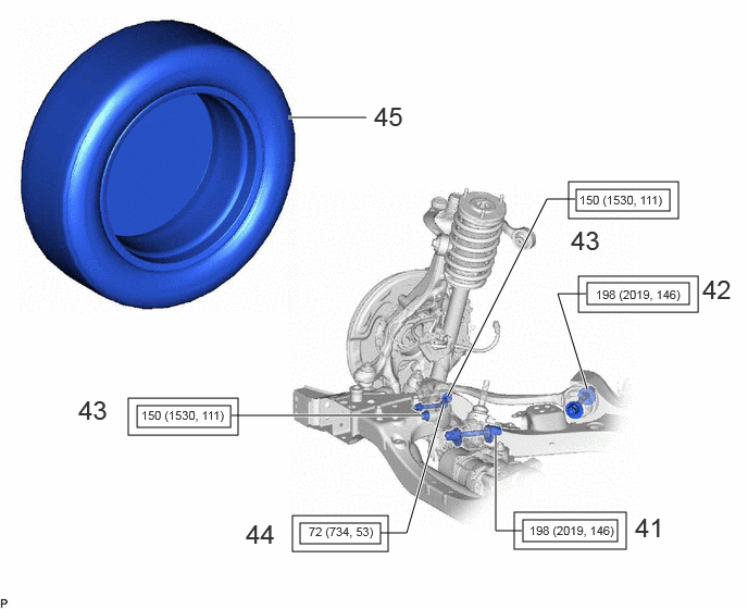
| 41 | FULLY TIGHTEN FRONT LOWER SUSPENSION ARM ASSEMBLY RH | 48620 | - | - | - |
| 42 | FULLY TIGHTEN LOWER NO. 2 SUSPENSION ARM ASSEMBLY RH | 48660C | - | - | - |
| 43 | FULLY TIGHTEN FRONT STABILIZER LINK ASSEMBLY RH | 48820B | - | - | - |
| 44 | FULLY TIGHTEN FRONT SHOCK ABSORBER ASSEMBLY RH | 48510 | - | - | - |
| 45 | FRONT TIRE RH | - | - | - | - |
|
|
Tightening torque for "Major areas involving basic vehicle performance such as moving/turning/stopping": N*m (kgf*cm, ft.*lbf) | - | - |
| Procedure | Part Name Code |
|
|
|
|
|---|---|---|---|---|---|
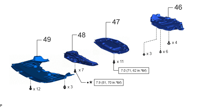
| 46 | REAR NO. 4 FLOOR BOARD SUB-ASSEMBLY | 58404B | - | - | - |
| 47 | FRONT COMPARTMEMT UNDER COVER ASSEMBLY | 51420A | - | - | - |
| 48 | FRONT LOWER SUSPENSION MEMBER PROTECTOR | 51219 | - | - | - |
| 49 | FRONT COMPARTMENT UNDER COVER | 51441N | - | - | - |
|
|
N*m (kgf*cm, ft.*lbf): Specified torque | - | - |
| ● | Non-reusable part | ★ | Precoated part |
| Procedure | Part Name Code |
|
|
|
|
|---|---|---|---|---|---|
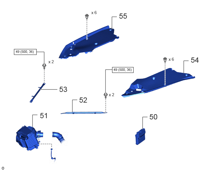
| 50 | FC CONTROL ECU | 898A1 | - | - | - |
| 51 | AIR CLEANER WITH ELEMENT ASSEMBLY WITH AIR CLEANER INLET | - | - | - | - |
| 52 | RADIATOR SUPPORT TO CROSS MEMBER BRACE SUB-ASSEMBLY LH | 53204E | - | - | - |
| 53 | RADIATOR SUPPORT TO CROSS MEMBER BRACE SUB-ASSEMBLY RH | 53204E | - | - | - |
| 54 | UPPER RADIATOR SUPPORT SEAL | 53292A | - | - | |
| 55 | RADIATOR COVER PLATE | 53209F | - | - | - |
|
|
N*m (kgf*cm, ft.*lbf): Specified torque | - | - |
| Procedure | Part Name Code |
|
|
|
|
|---|---|---|---|---|---|
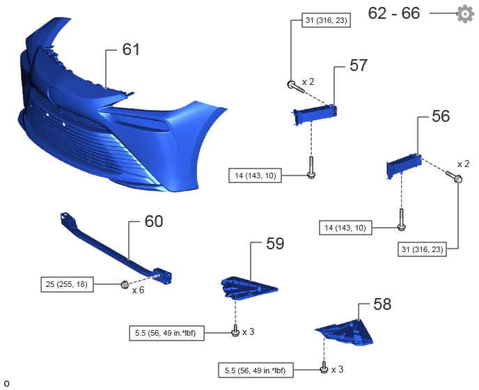
| 56 | REAR FRAME SIDE RAIL LH | 51116 | - | - | - |
| 57 | REAR FRAME SIDE RAIL RH | 51115 | - | - | - |
| 58 | RADIATOR SUPPORT EXTENSION LH | 53288B | - | - | - |
| 59 | RADIATOR SUPPORT EXTENSION RH | 53287B | - | - | - |
| 60 | FRONT NO. 2 BUMPER REINFORCEMENT SUB-ASSEMBLY | 52029B | - | - | - |
| 61 | FRONT BUMPER COVER | 52119A | - | - | - |
| 62 | CONNECT CABLE TO NEGATIVE AUXILIARY BATTERY TERMINAL | - | - | - | ()
|
| 63 | INITIALIZATION AFTER RECONNECTING AUXILIARY BATTERY TERMINAL | - | - | - | ()
|
| 64 | INSPECT AND ADJUST FRONT WHEEL ALIGNMENT | - | - | - | ()
|
| 65 | CHECK FOR SPEED SENSOR SIGNAL | - | - | - | ()
|
| 66 | PERFORM INITIALIZATION | - | - | - | ()
|
|
|
N*m (kgf*cm, ft.*lbf): Specified torque | - | - |
PROCEDURE

 48640
1.TEMPORARILY TIGHTEN FRONT LOWER SUSPENSION ARM ASSEMBLY LH

Insert the bolt from the front of the vehicle. Temporarily install the front lower suspension arm assembly LH with the nut.
- HINT:
-
Fully tighten the nut after stabilizing the suspension.
48620
2.TEMPORARILY TIGHTEN FRONT LOWER SUSPENSION ARM ASSEMBLY RH
Perform the same procedure as for the LH side.
48670A
3.TEMPORARILY TIGHTEN LOWER NO. 2 SUSPENSION ARM ASSEMBLY LH
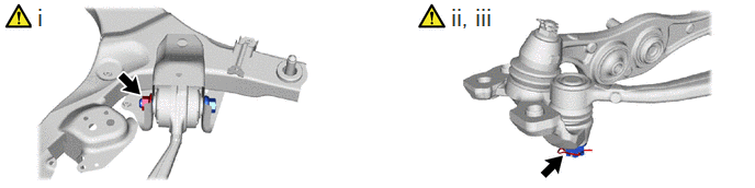
Insert the bolt from the front of the vehicle. Temporarily install the front lower suspension arm assembly LH with the nut.
- HINT:
-
Fully tighten the nut after stabilizing the suspension.
Install the lower No. 2 suspension arm assembly LH to the front lower ball joint assembly LH with the nut.
- Torque:
- 145 N*m (1479 kgf*cm, 107 ft.*lbf)
- NOTICE:
-
Keep the threads and taper free of oil and grease.
Install a new clip.
- NOTICE:
-
Further tighten the nut up to 60° if the holes for the clip are not aligned.
48660C
4.TEMPORARILY TIGHTEN LOWER NO. 2 SUSPENSION ARM ASSEMBLY RH
Perform the same procedure as for the LH side.
5.REMOVE HOLDING BAR
51100G
6.INSTALL FRONT FRAME ASSEMBLY
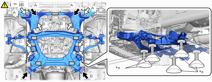
| *a | Attachment | *b | Engine Lifter |

|
Bolt | 
|
Nut |

|
Attachment placement location | - | - |
Support the front frame assembly with an engine lifter using 4 attachments or equivalent tools as shown in the illustration.
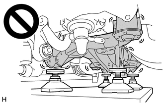
- CAUTION:
-
- ·
The rear suspension member sub-assembly is a very heavy component. Make sure that it is supported securely.
·If the rear suspension member sub-assembly is not securely supported, it may drop, resulting in serious injury.
- NOTICE:
-
Use attachments to keep the rear suspension member sub-assembly level.
Raise the rear suspension member sub-assembly until there is no clearance between the front frame assembly and vehicle body.
- NOTICE:
-
When raising the front frame assembly, be careful not to damage the vehicle body or other components installed to the vehicle.
Install the front frame assembly with the 4 bolts and 8 nuts.
- Torque:
- Bolt A : 120 N*m (1224 kgf*cm, 89 ft.*lbf)
- Bolt B : 170 N*m (1734 kgf*cm, 125 ft.*lbf)
- Nut A : 170 N*m (1734 kgf*cm, 125 ft.*lbf)
- Nut B : 120 N*m (1224 kgf*cm, 89 ft.*lbf)
- Nut C : 65 N*m (663 kgf*cm, 48 ft.*lbf)
7.REMOVE ENGINE SUPPORT BRIDGE
Remove the engine support bridge from the vehicle.
- NOTICE:
-
Make sure the engine support bridge does not interfere with the parts such as radiator support, engine hood or windshield glass when removing.
8.REMOVE ENGINE HANGER
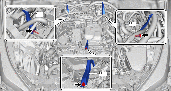
| *1 | Engine Hanger | - | - |
|
|
Bolt | - | - |
51474C
9.INSTALL FRONT COMPARTMENT SIDE COVER LH
51473D
10.INSTALL FRONT COMPARTMENT SIDE COVER RH
48811
11.INSTALL FRONT STABILIZER BAR
44250
12.INSTALL RACK AND PINION POWER STEERING GEAR ASSEMBLY
43212
13.TEMPORARILY TIGHTEN STEERING KNUCKLE LH
48520
14.TEMPORARILY TIGHTEN FRONT SHOCK ABSORBER ASSEMBLY LH
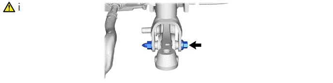
Insert the bolt from the rear of the vehicle. Temporarily install the front shock absorber assembly LH with the bolt and nut.
- NOTICE:
-
Because the nut has its own stopper, turn the bolt.
48810
15.TEMPORARILY TIGHTEN FRONT STABILIZER LINK ASSEMBLY LH
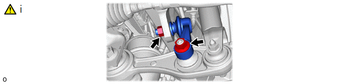
Temporarily tighten the front stabilizer link assembly LH with the 2 nuts.
- HINT:
-
If the ball joint turns together with the nut, use a 8 mm hexagon wrench to hold the stud bolt.
45470
16.CONNECT TIE ROD ASSEMBLY LH
|
|
()
|
48630D
17.CONNECT FRONT UPPER NO. 1 SUSPENSION ARM ASSEMBLY LH
|
|
()
|
48630E
18.CONNECT FRONT UPPER NO. 2 SUSPENSION ARM ASSEMBLY LH
Use the same procedure described for the front upper No. 1 suspension arm assembly LH.
43212
19.FULLY TIGHTEN STEERING KNUCKLE LH
47782
20.INSTALL FRONT DISC BRAKE DUST COVER LH
43512
21.INSTALL FRONT DISC LH
|
|
()
|
47750
22.INSTALL DISC BRAKE CYLINDER ASSEMBLY LH
|
|
()
|
89516F
23.INSTALL FRONT SKID CONTROL SENSOR WIRE LH
|
|
()
|
43211
24.TEMPORARILY TIGHTEN STEERING KNUCKLE RH
Perform the same procedure as for the LH side.
48510
25.TEMPORARILY TIGHTEN FRONT SHOCK ABSORBER ASSEMBLY RH
Perform the same procedure as for the LH side.
48820B
26.TEMPORARILY TIGHTEN FRONT STABILIZER LINK ASSEMBLY RH
Perform the same procedure as for the LH side.
45460
27.CONNECT TIE ROD ASSEMBLY RH
Perform the same procedure as for the LH side.
48610H
28.CONNECT FRONT UPPER NO. 1 SUSPENSION ARM ASSEMBLY RH
Perform the same procedure as for the LH side.
48610J
29.CONNECT FRONT UPPER NO. 2 SUSPENSION ARM ASSEMBLY RH
Perform the same procedure as for the LH side.
43211
30.FULLY TIGHTEN STEERING KNUCKLE RH
Perform the same procedure as for the LH side.
47781
31.INSTALL FRONT DISC BRAKE DUST COVER RH
Perform the same procedure as for the LH side.
43512
32.INSTALL FRONT DISC
Perform the same procedure as for the LH side.
47730
33.INSTALL DISC BRAKE CYLINDER ASSEMBLY RH
Perform the same procedure as for the LH side.
89516E
34.INSTALL FRONT SKID CONTROL SENSOR WIRE RH
Perform the same procedure as for the LH side.
35. STABILIZE SUSPENSION
|
|
()
|
48640
36.FULLY TIGHTEN FRONT LOWER SUSPENSION ARM ASSEMBLY LH
48670A
37.FULLY TIGHTEN LOWER NO. 2 SUSPENSION ARM ASSEMBLY LH
48810
38.FULLY TIGHTEN FRONT STABILIZER LINK ASSEMBLY LH
Install the front stabilizer link assembly LH with the 2 nut.
- Torque:
- 150 N*m (1530 kgf*cm, 111 ft.*lbf)
- HINT:
-
If the ball joint turns together with the nut, use a 8 mm hexagon wrench to hold the stud bolt.
48520
39.FULLY TIGHTEN FRONT SHOCK ABSORBER ASSEMBLY LH
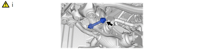
Install the front shock absorber assembly LH with the bolt and nut and temporarily tighten the bolt.
- NOTICE:
-
Because the nut has its own stopper, turn the bolt.
- Torque:
- 72 N*m (734 kgf*cm, 53 ft.*lbf)
40.INSTALL FRONT TIRE LH
48620
41.FULLY TIGHTEN FRONT LOWER SUSPENSION ARM ASSEMBLY RH
Perform the same procedure as for the LH side.
48660C
42.FULLY TIGHTEN LOWER NO. 2 SUSPENSION ARM ASSEMBLY RH
Perform the same procedure as for the LH side.
48820B
43.FULLY TIGHTEN FRONT STABILIZER LINK ASSEMBLY RH
Perform the same procedure as for the LH side.
48510
44.FULLY TIGHTEN FRONT SHOCK ABSORBER ASSEMBLY RH
Perform the same procedure as for the LH side.
45.INSTALL FRONT TIRE RH
Perform the same procedure as for the LH side.
58404B
46.INSTALL REAR NO. 4 FLOOR BOARD SUB-ASSEMBLY
51420A
47.INSTALL FRONT COMPARTMEMT UNDER COVER ASSEMBLY
51219
48.INSTALL FRONT LOWER SUSPENSION MEMBER PROTECTOR
51441N
49.INSTALL FRONT COMPARTMENT UNDER COVER
898A1
50.INSTALL FC CONTROL ECU
51.INSTALL AIR CLEANER WITH ELEMENT ASSEMBLY WITH AIR CLEANER INLET
53204E
52.INSTALL RADIATOR SUPPORT TO CROSS MEMBER BRACE SUB-ASSEMBLY LH
53209F
53.INSTALL RADIATOR SUPPORT TO CROSS MEMBER BRACE SUB-ASSEMBLY RH
53292A
54.INSTALL UPPER RADIATOR SUPPORT SEAL
53291B
55.INSTALL RADIATOR COVER PLATE
51116
56.INSTALL REAR FRAME SIDE RAIL LH
51115
57.INSTALL REAR FRAME SIDE RAIL RH
53288B
58.INSTALL RADIATOR SUPPORT EXTENSION LH
53287B
59.INSTALL RADIATOR SUPPORT EXTENSION RH
52029B
60.INSTALL FRONT NO. 2 BUMPER REINFORCEMENT SUB-ASSEMBLY
52119A
61.INSTALL FRONT BUMPER COVER
62.CONNECT CABLE TO NEGATIVE AUXILIARY BATTERY TERMINAL
63. INITIALIZATION AFTER RECONNECTING AUXILIARY BATTERY TERMINAL
Click hereGeneral>SETUP>WHEN REPLACING OR REMOVING/INSTALLING PARTS>WORK PROCEDURE
- HINT:
-
When disconnecting and reconnecting the auxiliary battery, there is an automatic learning function that completes learning when the respective system is used.
-
Click hereGeneral>SETUP>WHEN DISCONNECTING OR RECONNECTING BATTERY TERMINAL>AUTOMATIC LEARNING CHART
64.INSPECT AND ADJUST FRONT WHEEL ALIGNMENT
65.CHECK FOR SPEED SENSOR SIGNAL
66. PERFORM INITIALIZATION