1AD-FTV LUBRICATION OIL PUMP INSTALLATION
CAUTION / NOTICE / HINT
- NOTICE:
- ·
When replacing the injectors (including shuffling the injectors between the cylinders), common rail, intake manifold or cylinder head, it is necessary to replace the injection pipes with new ones.
·When replacing the fuel supply pump, common rail, intake manifold or cylinder head, it is necessary to replace the fuel inlet pipe with a new one.
PROCEDURE

 1.INSTALL STUD BOLT
- HINT:
-
If a stud bolt is deformed or its threads are damaged, replace it.
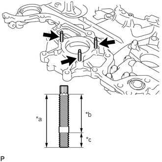
| *a | 34 mm (1.34 in.) |
| *b | 25 mm (0.984 in.) |
| *c | 9.0 mm (0.354 in.) |
Using an E6 "TORX" wrench, install the 3 stud bolts.
- Torque:
- 3.0 N*m (31 kgf*cm, 27 in.*lbf)
11301C
2.INSTALL FRONT CRANKSHAFT OIL SEAL
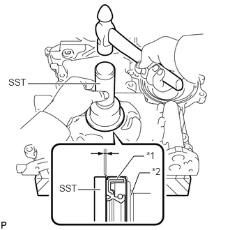
| *1 | Front Crankshaft Oil Seal |
| *2 | Timing Chain Cover Sub-assembly |
Using SST and a hammer, tap in a new front crankshaft oil seal until its surface is flush with the timing chain cover sub-assembly edge.
- SST
- 09223-50010
- Standard depth:
0 to 0.6 mm (0 to 0.236 in.)
- NOTICE:
- ·
Keep the lip of the front crankshaft oil seal free from foreign matter.
·Do not tap in the front crankshaft oil seal at an angle.
Apply MP grease to the lip of the front crankshaft oil seal.
- NOTICE:
- ·
Do not allow foreign matter to contact the lip of the front crankshaft oil seal.
·Do not allow MP grease to contact the dust seal.
3.INSTALL STRAIGHT SCREW PLUG
Using a 10 mm socket hexagon wrench, install a new gasket and the straight screw plug.
- Torque:
- 19 N*m (194 kgf*cm, 14 ft.*lbf)
11302
4.INSTALL TIMING CHAIN COVER SUB-ASSEMBLY
Remove any old seal packing material.
Install a new gasket and O-ring to the timing chain cover sub-assembly.
Apply seal packing in a continuous line to the timing chain cover sub-assembly as shown in the following illustration.
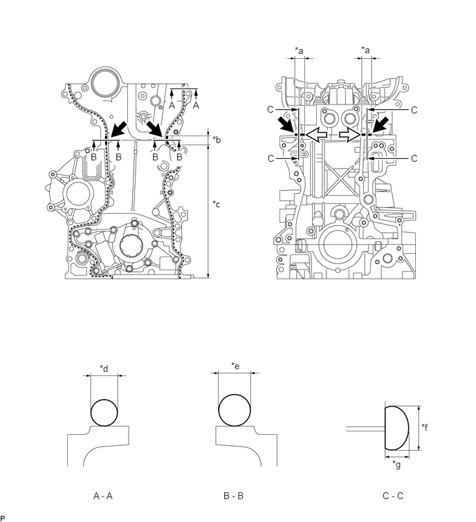
| *a | 15 mm (0.591 in.) or more | *b | 30 mm (1.18 in.) |
| *c | 310.5 mm (1 ft.) | *d | 2.0 to 4.0 mm (0.0787 to 0.157 in.) |
| *e | 8.0 to 10 mm (0.315 to 0.394 in.) | *f | 13 mm (0.512 in.) |
| *g | 6.0 mm (0.236 in.) | - | - |
- Seal packing:
Toyota Genuine Seal Packing Black, Three Bond 1207B or equivalent
- Apply Seal Packing as Follows:
Area Seal Packing Diameter (Round) Seal Packing Dimension (Flat) Seal Packing Application Length A - A 2.0 to 4.0 mm (0.0787 to 0.157 in.) - - B - B 8.0 to 10 mm (0.315 to 0.394 in.) - 30 mm (1.18 in.) C - C - 13 mm (0.512 in.) or more wide and 6.0 mm (0.236 in.) or more thick 15 mm (0.591 in.)
- NOTICE:
- ·
Be sure to clean and degrease the contact surfaces, especially the 4 areas indicated by the arrows in the illustration.
·When the contact surfaces are wet, wipe them off with an oil-free cloth before applying seal packing.
·When applying seal packing to area C - C, apply it in the direction of the white arrows in the illustration.
·Install the timing chain cover sub-assembly within 3 minutes and tighten the bolts within 15 minutes after applying seal packing.
·Do not start the engine for at least 4 hours after installation.
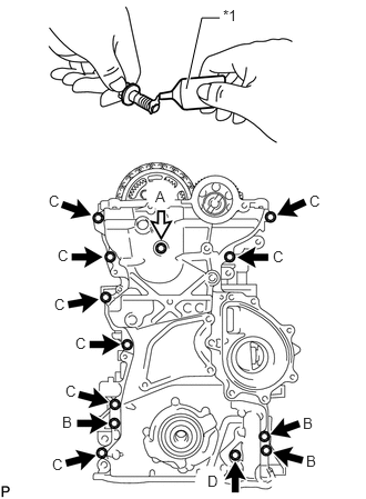
| *1 | Adhesive |

|
Bolt and New Seal Washer |
Apply adhesive to the 3 bolts labeled B and bolt labeled D.
- Adhesive:
Toyota Genuine Adhesive 1324, Three Bond 1324 or equivalent
Temporarily install the timing chain cover sub-assembly and a new seal washer with the 13 bolts.
- Bolt Length:
Item Specified Condition Bolt A 60 mm (2.36 in.) Bolt B 30 mm (1.18 in.) Bolt C 30 mm (1.18 in.) Bolt D 45 mm (1.77 in.)
- HINT:
-
Bolt B and C are identical.
Tighten the 12 bolts labeled B, C and D.
- Torque:
- 23 N*m (229 kgf*cm, 17 ft.*lbf)
Tighten the bolt labeled A.
- Torque:
- 21 N*m (214 kgf*cm, 15 ft.*lbf)
13471
5.INSTALL CRANKSHAFT PULLEY
6.INSTALL ENGINE WATER PUMP ASSEMBLY
11401G
7.CONNECT CRANKSHAFT POSITION SENSOR WIRE HARNESS
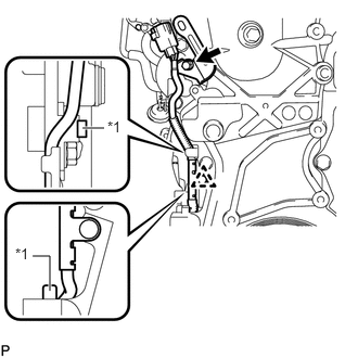
| *1 | Protrusion |
Connect the crankshaft position sensor wire harness with the bolt and clip.
- Torque:
- 8.8 N*m (90 kgf*cm, 78 in.*lbf)
- NOTICE:
-
Make sure the crankshaft position sensor wire harness is installed in the position shown in the illustration.
11301K
8.INSTALL CAMSHAFT POSITION SENSOR
15104
9.INSTALL OIL STRAINER SUB-ASSEMBLY
Install a new O-ring to the oil strainer sub-assembly.
Apply a light coat of engine oil to the O-ring.
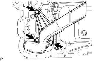
Install the oil strainer sub-assembly with the 3 bolts.
- Torque:
- for bolt A : 42 N*m (428 kgf*cm, 31 ft.*lbf)
- for bolt B : 9.0 N*m (92 kgf*cm, 80 in.*lbf)
15605A
10.INSTALL OIL CHECK VALVE SUB-ASSEMBLY
Using a 5 mm hexagon wrench, install the oil check valve sub-assembly with the bolt.
- Torque:
- 9.0 N*m (92 kgf*cm, 80 in.*lbf)
15677
11.INSTALL OIL FILTER BRACKET
Install a new gasket to the oil filter bracket.
Install the oil filter bracket with the 4 bolts.
- Torque:
- 9.0 N*m (92 kgf*cm, 80 in.*lbf)
15350A
12.INSTALL OIL PRESSURE SWITCHING VALVE ASSEMBLY
13.INSTALL OIL FILTER ELEMENT
12102A
14.INSTALL NO. 2 OIL PAN SUB-ASSEMBLY
Remove any old seal packing material.
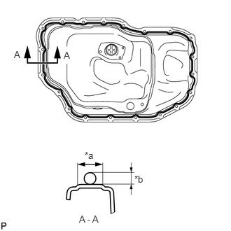
| *a | 12 mm (0.472 in.) |
| *b | 4.0 to 7.0 mm (0.157 to 0.276 in.) |
Apply seal packing in a continuous line as shown in the illustration.
- Seal packing:
Toyota Genuine Seal Packing Black, Three Bond 1207B or equivalent
- Standard Seal Packing Dimension:
Area Seal Packing Diameter Acceptable Seal Packing Application Range A - A 4.0 to 7.0 mm (0.157 to 0.276 in.) 12 mm (0.472 in.)
- NOTICE:
- ·
Remove any oil from the contact surface.
·Install the No. 2 oil pan sub-assembly within 3 minutes and tighten the bolts within 10 minutes after applying seal packing.
·Do not start the engine for at least 4 hours after installation.
Install the No. 2 oil pan sub-assembly with the 18 bolts and 2 nuts.
- Torque:
- 11 N*m (107 kgf*cm, 8 ft.*lbf)
11201
15.INSTALL CYLINDER HEAD COVER SUB-ASSEMBLY
Remove any old seal packing material.
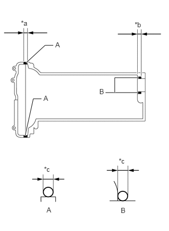
| *a | 8.0 mm (0.315 in.) |
| *b | 10 mm (0.394 in.) |
| *c | 6.0 mm (0.236 in.) |
Apply seal packing to the cylinder head as shown in the illustration.
- Seal packing:
Toyota Genuine Seal Packing Black, Three Bond 1207B or equivalent
- Standard Seal Packing Dimension:
Area Seal Packing Diameter Seal Packing Application Length A 6.0 mm (0.236 in.) 8.0 mm (0.315 in.) B 6.0 mm (0.236 in.) 10 mm (0.394 in.)
Install a new cylinder head cover gasket to the cylinder head cover sub-assembly.
Install the cylinder head cover gasket so that the triangle tabs of the cylinder head cover gasket are aligned with the protrusions of the cylinder head cover sub-assembly as shown in the parts of the illustration labeled A and B.
Install the cylinder head cover gasket to the groove of the cylinder head cover moving from C and D in the direction of the black arrows shown in the illustration.
Install the cylinder head cover gasket to the groove of the cylinder head cover sub-assembly moving from C and D towards E as shown by the white arrows in the illustration.
Install the cylinder head gasket to the groove of the cylinder head cover sub-assembly moving from D towards F as shown by the striped arrow in the illustration.
Install the cylinder head cover gasket to the cylinder head cover sub-assembly pins and cutouts as shown in the parts of the illustration labeled G and H.
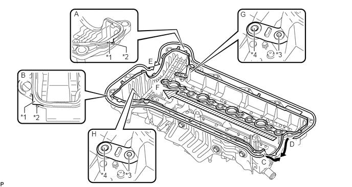
| *1 | Triangle Tab of Cylinder Head Cover Gasket | *2 | Protrusion of Cylinder Head Cover Sub-assembly |
| *3 | Cylinder Head Cover Sub-assembly Pin | *4 | Cutout of Cylinder Head Cover Sub-assembly |
- NOTICE:
-
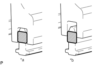 0.677,1.927 0.99,2.083 0.313,0.156 10 *a 2.333,1.938 2.646,2.094 0.313,0.156 10 *b
*a CORRECT *b INCORRECT 
Rib of Cylinder Head Cover Gasket
-
Make sure that the rib of the cylinder head cover gasket is securely inserted into the groove of the cylinder head cover sub-assembly.
|
|
Nut |
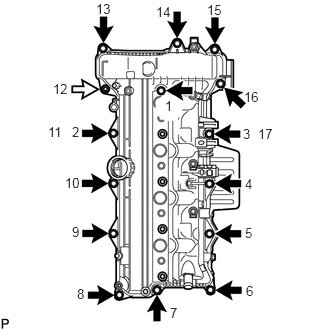
Install the cylinder head cover sub-assembly with the 14 bolts and nut, and tighten the bolts and nut in the order shown in the illustration.
- Torque:
- 10 N*m (102 kgf*cm, 7 ft.*lbf)
- HINT:
-
Partially tighten the bolt indicated by the number 6 in the illustration until the cylinder head cover sub-assembly contacts the cylinder head sub-assembly, and then tighten the bolts and nut in the order shown in the illustration.
23699A
16.INSTALL NOZZLE HOLDER CLAMP SEAT
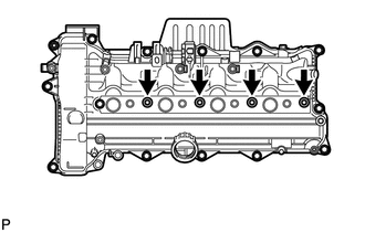
Install the 4 nozzle holder clamp seats.
- Torque:
- 10 N*m (102 kgf*cm, 7 ft.*lbf)
12108
17.INSTALL OIL FILLER CAP SUB-ASSEMBLY
12261
18.INSTALL PCV HOSE
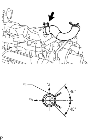
| *1 | Paint Mark |
| *a | Upper Side |
| *b | Front Side of Vehicle |
Install the PCV hose to the cylinder head cover sub-assembly, and slide the clamp to secure the hose.
- HINT:
-
The direction of the clamp is indicated in the illustration.
19.INSTALL NO. 1 WIRING HARNESS CLAMP BRACKET
Install the No. 1 wiring harness clamp bracket with the bolt.
- Torque:
- 9.0 N*m (92 kgf*cm, 80 in.*lbf)
25760A
20.INSTALL VACUUM TRANSMITTING HOSE ASSEMBLY
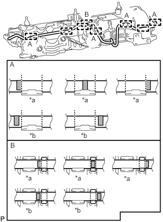
| *a | CORRECT |
| *b | INCORRECT |

|
Paint Mark |
Attach the 8 clamps to install the 2 vacuum transmitting hoses.
- HINT:
- ·
Make sure that the paint marks of the vacuum transmitting hoses at the locations labeled A in the illustration are aligned as shown in the illustration. Any of the "CORRECT" alignments are acceptable for each location.
·Make sure that the paint marks of the vacuum transmitting hoses at the locations labeled B in the illustration are aligned as shown in the illustration. Any of the "CORRECT" alignments are acceptable for each location.
25860
21.INSTALL NO. 1 VACUUM SWITCHING VALVE ASSEMBLY
22.INSTALL INJECTOR ASSEMBLY
23762
23.INSTALL NO. 2 NOZZLE LEAKAGE PIPE
Temporarily install the No. 2 nozzle leakage pipe and a new gasket with the check valve and bolt.
Tighten the check valve.
- Torque:
- 32 N*m (321 kgf*cm, 23 ft.*lbf)
Tighten the bolt.
- Torque:
- 32 N*m (321 kgf*cm, 23 ft.*lbf)
23274D
24.INSTALL NO. 3 FUEL HOSE
Install the No. 3 fuel hose to the fuel supply pump assembly and No. 2 nozzle leakage pipe, and slide the 2 clamps to secure the hose.
23901E
25.INSTALL FUEL TUBE SUB-ASSEMBLY
23292D
26.INSTALL FUEL HOSE PROTECTOR
16323
27.INSTALL WATER INLET HOUSING
Install a new gasket and the water inlet housing with the 3 nuts.
- Torque:
- 9.0 N*m (92 kgf*cm, 80 in.*lbf)
16281
28.INSTALL NO. 4 WATER BY-PASS HOSE
Install the No. 4 water by-pass hose to the water inlet housing and elbow, and slide the 2 clamps to secure the hose.
16278
29.INSTALL NO. 2 WATER BY-PASS PIPE
Install a new O-ring to the No. 2 water by-pass pipe.
Install the No. 2 water by-pass pipe with the 2 bolts.
- Torque:
- 11 N*m (112 kgf*cm, 8 ft.*lbf)
15781
30.INSTALL NO. 1 OIL COOLER BRACKET
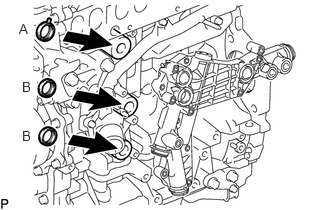
Apply engine oil to the 2 new gaskets labeled B in the illustration.
- NOTICE:
-
Do not apply engine oil to the new gasket labeled A in the illustration.
Install the 3 new gaskets to the No. 1 oil cooler bracket.
Install the No. 1 oil cooler bracket with the 6 bolts and nut.
- Torque:
- 10 N*m (102 kgf*cm, 7 ft.*lbf)
15481
31.INSTALL NO. 1 TURBO OIL PIPE
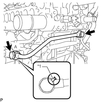
| *1 | Gasket |
Install the No. 1 turbo oil pipe and 2 new gaskets with the 2 union bolts.
- Torque:
- 35 N*m (357 kgf*cm, 26 ft.*lbf)
- NOTICE:
-
Make sure the gasket of union bolt A contacts the No. 1 turbo oil pipe as shown in the illustration when tightening the union bolt.
16279
32.INSTALL NO. 3 WATER BY-PASS PIPE
Install a new O-ring to the No. 3 water by-pass pipe.
Install the No. 3 water by-pass pipe with the 2 bolts.
- Torque:
- 21 N*m (214 kgf*cm, 15 ft.*lbf)
16296
33.INSTALL NO. 8 WATER BY-PASS HOSE
Install the No. 8 water by-pass hose to the No. 3 water by-pass pipe, and slide the clamp to secure the hose.
16283
34.INSTALL NO. 6 WATER BY-PASS HOSE
Install the No. 6 water by-pass hose to the water outlet, and slide the clamp to secure the hose.
15710
35.INSTALL OIL COOLER ASSEMBLY
16261
36.INSTALL WATER BY-PASS HOSE
12581A
37.INSTALL NO. 1 CYLINDER BLOCK INSULATOR
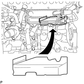
Install the No. 1 cylinder block insulator to the cylinder block sub-assembly.
- NOTICE:
-
Be sure to install the oil cooler assembly before installing the No. 1 cylinder block insulator.
17111
38.INSTALL INTAKE MANIFOLD
17112
39.INSTALL NO. 2 INTAKE MANIFOLD
12631A
40.INSTALL ENGINE COVER BRACKET
17696
41.INSTALL GAS FILTER BRACKET
23265
42.INSTALL NO. 1 GAS FILTER
89421C
43.INSTALL DIESEL TURBO PRESSURE SENSOR
17853B
44.INSTALL INTAKE MANIFOLD INSULATOR
23810A
45.INSTALL COMMON RAIL ASSEMBLY
Install the common rail assembly with the 2 bolts.
- Torque:
- 21 N*m (209 kgf*cm, 15 ft.*lbf)
23282D
46.INSTALL NO. 4 FUEL HOSE
Install the No. 4 fuel hose to the common rail assembly and No. 2 nozzle leakage pipe, and slide the 2 clamps to secure the hose.
23701
47.INSTALL INJECTION PIPE SUB-ASSEMBLY
23804C
48.INSTALL FUEL INLET PIPE SUB-ASSEMBLY
11452
49.INSTALL ENGINE OIL LEVEL DIPSTICK GUIDE
Install a new O-ring to the engine oil level dipstick guide.
Install the engine oil level dipstick guide with the 2 bolts.
- Torque:
- 24 N*m (245 kgf*cm, 18 ft.*lbf)
Install the engine oil level dipstick.
25800
50.INSTALL ELECTRIC EGR CONTROL VALVE ASSEMBLY
25602
51.INSTALL NO. 2 EGR PIPE SUB-ASSEMBLY
25625
52.INSTALL EGR VALVE BRACKET
Install the EGR valve bracket with the 3 bolts.
- Torque:
- 24 N*m (245 kgf*cm, 18 ft.*lbf)
16296
53.CONNECT NO. 8 WATER BY-PASS HOSE
16295
54.INSTALL NO. 7 WATER BY-PASS HOSE
26100
55.INSTALL DIESEL THROTTLE BODY ASSEMBLY
Install a new gasket and the diesel throttle body assembly with the 2 bolts and 2 nuts.
- Torque:
- 11 N*m (112 kgf*cm, 8 ft.*lbf)
Connect the No. 6 water by-pass hose and No. 7 water by-pass hose to the diesel throttle body assembly, and slide the 2 clamps to secure the hose.
16620
56.INSTALL V-RIBBED BELT TENSIONER ASSEMBLY
Install the V-ribbed belt tensioner assembly with the 3 bolts.
- Torque:
- 20 N*m (204 kgf*cm, 15 ft.*lbf)
- NOTICE:
-
As the heads of the bolts are not as thick as those of typical bolts, be careful not to damage them during installation.
12315A
57.INSTALL ENGINE MOUNTING BRACKET
Temporarily install the engine mounting bracket with the 2 bolts labeled A.
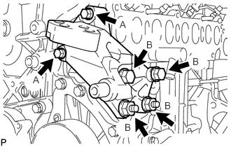
Temporarily install the 2 bolts and 2 nuts labeled B in the illustration.
Tighten the 2 bolts labeled A in the illustration.
- Torque:
- 28 N*m (286 kgf*cm, 21 ft.*lbf)
Tighten the 2 bolts and 2 nuts labeled B in the illustration.
- Torque:
- 80 N*m (816 kgf*cm, 59 ft.*lbf)
16288
58.INSTALL NO. 4 WATER BY-PASS PIPE
Install a new O-ring to the No. 4 water by-pass pipe.
Install the No. 4 water by-pass pipe with the bolt.
- Torque:
- 11 N*m (112 kgf*cm, 8 ft.*lbf)
16604
59.INSTALL NO. 2 IDLER PULLEY SUB-ASSEMBLY
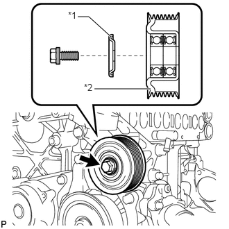
| *1 | No. 2 Idler Pulley Cover Plate |
| *2 | No. 2 Idler Pulley Sub-assembly |
Install the No. 2 idler pulley sub-assembly and No. 2 idler pulley cover plate with the bolt.
- Torque:
- 40 N*m (408 kgf*cm, 30 ft.*lbf)
- NOTICE:
-
Make sure the No. 2 idler pulley cover plate is facing the direction shown in the illustration.
16603
60.INSTALL NO. 1 IDLER PULLEY SUB-ASSEMBLY
Install the No. 1 idler pulley sub-assembly with the bolt.
- Torque:
- 40 N*m (408 kgf*cm, 30 ft.*lbf)
16649B
61.INSTALL IDLER PULLEY COVER PLATE
Install the idler pulley cover plate to the No. 1 idler pulley sub-assembly.
29300
62.INSTALL VACUUM PUMP ASSEMBLY
Apply a light coat of engine oil to 2 new O-rings.
Install the 2 O-rings to the vacuum pump assembly.
Install the vacuum pump assembly with 3 new bolts.
- Torque:
- 21 N*m (214 kgf*cm, 15 ft.*lbf)
Connect the vacuum hose.
27020
63.INSTALL GENERATOR ASSEMBLY
64.CONNECT ENGINE WIRE
Connect the connectors and attach the clamps, and then connect the engine wire to the engine with the bracket bolts.
65.INSTALL ENGINE ASSEMBLY