AXLE AND DIFFERENTIAL REAR AXLE HUB BOLT REPLACEMENT
CAUTION / NOTICE / HINT
The necessary procedures (adjustment, calibration, initialization, or registration) that must be performed after parts are removed and installed, or replaced during rear axle hub bolt removal/installation are shown below.
| Replaced Part or Performed Procedure | Necessary Procedure | Effect/Inoperative Function when Necessary Procedure not Performed | Link |
|---|---|---|---|
|
*: When performing learning using the GTS. Click here( |
|||
| Auxiliary battery terminal is disconnected/reconnected | Perform steering sensor zero point calibration | Lane control system | ( ) |
| Parking support brake system (for HV model)* | |||
| Pre-collision system | |||
| Memorize steering angle neutral point | Parking assist monitor system | ()
|
|
| Panoramic view monitor system (for HV model) | ()
|
||
| Reset back door close position | Power back door system (for HV model) | ()
|
|
| Power back door initialization | Power door lock control system | ()
|
|
- NOTICE:
-
After the ignition switch is turned off, the navigation system requires approximately a minute to record various types of memory and settings. As a result, after turning the ignition switch off, wait a minute or more before disconnecting the cable from the negative (-) auxiliary battery terminal.
- HINT:
- ·
Use the same procedure for the RH and LH sides.
·The following procedure is for the LH side.
PROCEDURE

 1.DISABLE BRAKE CONTROL (w/o Vacuum Brake Booster)
Click hereBrake>BRAKE (REAR)>REAR BRAKE>REMOVAL
2.REMOVE REAR WHEEL
890C0A
3.DISCONNECT NO. 2 PARKING BRAKE WIRE ASSEMBLY
47319F
4.DISCONNECT REAR FLEXIBLE HOSE LH
for 2WD: Click hereDrivetrain>AXLE AND DIFFERENTIAL>REAR AXLE CARRIER (for 2WD)>REMOVAL
for 4WD/AWD: Click hereDrivetrain>AXLE AND DIFFERENTIAL>REAR AXLE CARRIER (for 4WD/AWD)>REMOVAL
5.DISCONNECT REAR DISC BRAKE CALIPER ASSEMBLY LH
for 2WD: Click hereDrivetrain>AXLE AND DIFFERENTIAL>REAR AXLE CARRIER (for 2WD)>REMOVAL
for 4WD/AWD: Click hereDrivetrain>AXLE AND DIFFERENTIAL>REAR AXLE CARRIER (for 4WD/AWD)>REMOVAL
42431
6.REMOVE REAR DISC
Click hereBrake>BRAKE (REAR)>REAR BRAKE>REMOVAL
42312E
7.REMOVE REAR AXLE HUB BOLT
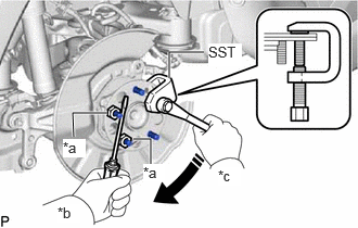
| *a | Service Nut |
| *b | Hold |
| *c | Turn |
Temporarily install 2 service nuts to the rear axle hub bolts as shown in the illustration.
- Recommended service nut:
Thread diameter: 12.0 mm (0.472 in.)
Thread pitch: 1.5 mm (0.0591 in.)
- NOTICE:
-
Install the service nuts to prevent damage to the rear axle hub bolts.
Using SST and a screwdriver or an equivalent tool to hold the rear axle hub and bearing assembly, remove the rear axle hub bolt.
- SST
- 09650-17011
- NOTICE:
-
Do not damage the threads of the rear axle hub bolts.
42312E
8.INSTALL REAR AXLE HUB BOLT
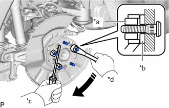
| *a | Service Nut |
| *b | Washer |
| *c | Hold |
| *d | Turn |
Temporarily install a new rear axle hub bolt to the rear axle hub and bearing assembly.
Install a washer and service nut to the rear axle hub bolt as shown in the illustration.
- Recommended service nut:
Thread diameter: 12.0 mm (0.472 in.)
Thread pitch: 1.5 mm (0.0591 in.)
- HINT:
-
Recommended washer thickness is 5 mm (0.197 in.) or more.
Using a screwdriver or an equivalent tool to hold the rear axle hub and bearing assembly, install the rear axle hub bolt by tightening the service nut.
- NOTICE:
- ·
Install the service nuts to prevent damage to the rear axle hub bolts.
·Do not damage the threads of the rear axle hub bolts.
Remove the 3 service nuts and washer from the 3 rear axle hub bolts.
42431
9.INSTALL REAR DISC
10.INSTALL REAR DISC BRAKE CALIPER ASSEMBLY LH
for 2WD: Click hereDrivetrain>AXLE AND DIFFERENTIAL>REAR AXLE CARRIER (for 2WD)>INSTALLATION
for 4WD/AWD: Click hereDrivetrain>AXLE AND DIFFERENTIAL>REAR AXLE CARRIER (for 4WD/AWD)>INSTALLATION
47319F
11.CONNECT REAR FLEXIBLE HOSE LH
for 2WD: Click hereDrivetrain>AXLE AND DIFFERENTIAL>REAR AXLE CARRIER (for 2WD)>INSTALLATION
for 4WD/AWD: Click hereDrivetrain>AXLE AND DIFFERENTIAL>REAR AXLE CARRIER (for 4WD/AWD)>INSTALLATION
890C0A
12.CONNECT NO. 2 PARKING BRAKE WIRE ASSEMBLY
13.INSTALL REAR WHEEL
14.CONNECT CABLE TO NEGATIVE AUXILIARY BATTERY TERMINAL (w/o Vacuum Brake Booster)
Connect the reservoir level switch connector.
Connect the cable to the negative (-) auxiliary battery terminal.
Click hereGeneral>MAINTENANCE>A25A-FXS AUXILIARY BATTERY>INSTALLATION
Perform the following procedure if air bleeding is not necessary:
Turn the power switch on (READY).
Depress the brake pedal and release it.