STEERING COLUMN STEERING COLUMN ASSEMBLY(for Manual Tilt and Manual Telescopic Steering Column) INSTALLATION
PROCEDURE

 45250
1.INSTALL STEERING COLUMN ASSEMBLY
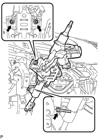
Install the steering column with the bolt and 2 nuts.
- Torque:
- 21 N*m (214 kgf*cm, 16 ft.*lbf)
Connect the connectors and wire harness clamps.
45203
2.INSTALL NO. 2 STEERING INTERMEDIATE SHAFT SUB-ASSEMBLY
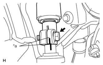
Align the matchmarks on the No. 2 steering intermediate shaft and power steering gear.
| *a | Matchmark |
Install the bolt.
- Torque:
- 35 N*m (357 kgf*cm, 26 ft.*lbf)
45220
3.INSTALL STEERING INTERMEDIATE SHAFT ASSEMBLY
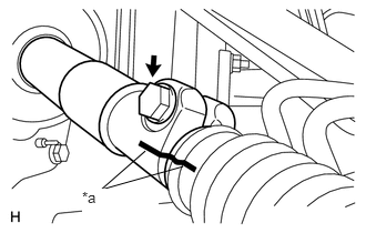
Align the matchmarks on the steering intermediate shaft and No. 2 steering intermediate shaft.
| *a | Matchmark |
Install the bolt.
- Torque:
- 35 N*m (357 kgf*cm, 26 ft.*lbf)
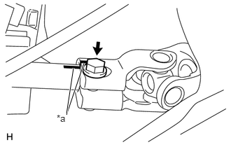
Align the matchmarks on the steering column and steering intermediate shaft.
| *a | Matchmark |
Install the bolt.
- Torque:
- 35 N*m (357 kgf*cm, 26 ft.*lbf)
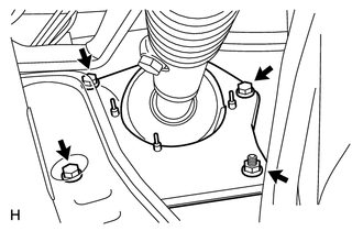
Install the 3 bolts and nut.
- Torque:
- 5.0 N*m (51 kgf*cm, 44 in.*lbf)
87201F
4.INSTALL NO. 3 AIR DUCT SUB-ASSEMBLY
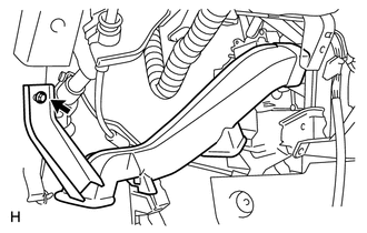
Install the air duct with the bolt.
73900
5.INSTALL LOWER NO. 1 INSTRUMENT PANEL AIRBAG ASSEMBLY
55046A
6.INSTALL LOWER INSTRUMENT PANEL FINISH PANEL SUB-ASSEMBLY LH
53601
7.INSTALL HOOD LOCK CONTROL LEVER SUB-ASSEMBLY
55318C
8.INSTALL INSTRUMENT SIDE PANEL LH
62112
9.INSTALL COWL SIDE TRIM BOARD LH
67914
10.INSTALL FRONT DOOR SCUFF PLATE LH (for Regular Cab)
11.INSTALL COMBINATION SWITCH WITH SPIRAL CABLE
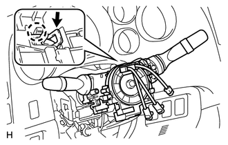
Using pliers, grip the claws of the clamp and install the combination switch with spiral cable to the steering column assembly with the clamp.
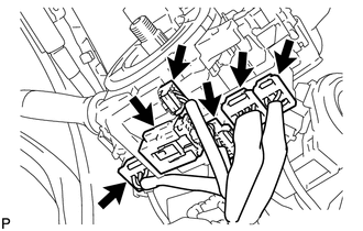
Connect the 6 connectors to the combination switch with spiral cable.
45286B
12.INSTALL UPPER STEERING COLUMN COVER
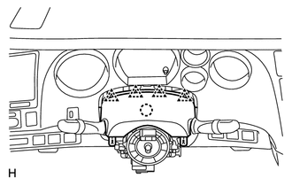
Attach the claw to install the upper steering column cover.
Attach the 4 clips.
45287
13.INSTALL LOWER STEERING COLUMN COVER
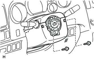
Attach the 2 claws to install the lower steering column cover.
Install the 2 screws.
- Torque:
- 2.0 N*m (20 kgf*cm, 18 in.*lbf)
14.ADJUST SPIRAL CABLE
45100
15.INSTALL STEERING WHEEL ASSEMBLY
16.INSPECT STEERING WHEEL CENTER POINT
45130
17.INSTALL STEERING PAD
45187
18.INSTALL LOWER NO. 3 STEERING WHEEL COVER
45186
19.INSTALL LOWER NO. 2 STEERING WHEEL COVER
20.CONNECT CABLE TO NEGATIVE BATTERY TERMINAL
- Torque:
- 5.4 N*m (55 kgf*cm, 48 in.*lbf)
- NOTICE:
-
When disconnecting the cable, some systems need to be initialized after the cable is reconnected (See page General>INTRODUCTION>REPAIR INSTRUCTION>INITIALIZATION).
21.CHECK SRS WARNING LIGHT