B58 ENGINE MECHANICAL ENGINE MOUNTING REMOVAL
CAUTION / NOTICE / HINT
- CAUTION:
- ·
Vehicle may slip off the vehicle hoist if the vehicle hoist is handled incorrectly.
Danger! Life-threatening injuries!
-Observe safety information on raising the vehicle using a vehicle hoist.
-For additional information see:
Click hereGeneral>INTRODUCTION>REPAIR INSTRUCTION>VEHICLE LIFT AND SUPPORT LOCATIONS
- ·
Motor vehicle may slip off the vehicle hoist if the weight is distributed unevenly.
Danger! Life-threatening injuries!
-Ensure there is a specific weight compensation on the motor vehicle.
- ·
Motor vehicle may slip off the vehicle hoist where components are supported.
Danger! Life-threatening injuries!
-Secure the vehicle hoist against lowering and lifting.
PROCEDURE

 1.DISCONNECT CABLE FROM NEGATIVE BATTERY TERMINAL
Click hereGeneral>MAINTENANCE>B58 BATTERY>REMOVAL
2.REMOVE AND INSTALL BONNET HOOD SUPPORT ASSEMBLY
12601B
3.REMOVE NO. 1 ENGINE COVER SUB-ASSEMBLY
4.REMOVE NO. 1 INTEGRATION RELAY
5.REMOVE ENGINE ROOM ECM BOX
6.REMOVE WHEEL ASSEMBLY
53826A
7.REMOVE FRONT FENDER UPPER PROTECTOR LH
53825A
8.REMOVE FRONT FENDER UPPER PROTECTOR RH
- HINT:
-
Use the same procedure as for the LH side.
51219
9.REMOVE FRONT SUSPENSION MEMBER LOWER PROTECTOR
53879
10.REMOVE FRONT FENDER LINER LH
53878
11.REMOVE FRONT FENDER LINER RH
- HINT:
-
Use the same procedure as for the LH side.
25051
12.REMOVE EXHAUST MANIFOLD CONVERTER SUB-ASSEMBLY
13.INSTALL ENGINE HANGER
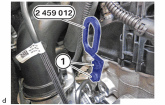
Guide in and position special tool 2 459 012 on cylinder head.
- SST
- 09200-WA610
Tighten the screws (1) of special tool 2 459 012.
- SST
- 09200-WA610
- Torque:
- 21.5 N*m (219 kgf*cm, 16 ft.*lbf)
14.INSTALL ENGINE SUPPORT BRIDGE
for Type A:
Click hereSuspension>FRONT SUSPENSION>FRONT SUSPENSION MEMBER>REMOVAL
for Type B:
Click hereSuspension>FRONT SUSPENSION>FRONT SUSPENSION MEMBER>REMOVAL
12361
15.SEPARATE FRONT ENGINE MOUNTING INSULATOR LH
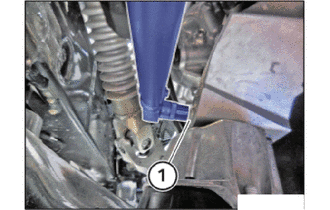
Release the E14 bolt (1) from the top.
12361
16.SEPARATE FRONT ENGINE MOUNTING INSULATOR RH
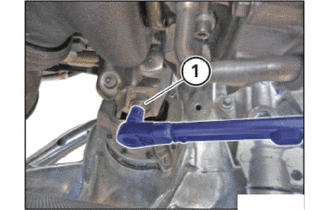
Release the E14 bolt (1) from the top.
52822
17.REMOVE AIR INTAKE DUCT LH
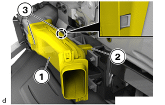
Lift air intake duct LH (1) with the guide (2), detach it from the latch mechanisms (3) to the rear and remove.
52821
18.REMOVE AIR INTAKE DUCT RH
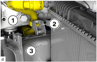
Unclip coolant line (1) and bracket (2) from the air intake duct RH (3).
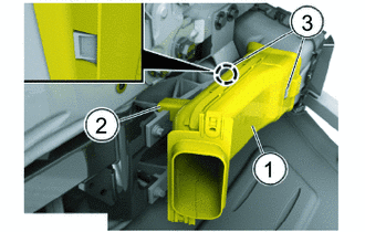
Lift air intake duct RH (1) with the guide (2), detach it from the latch mechanisms (3) to the rear and remove.
45220
19.REMOVE STEERING INTERMEDIATE SHAFT ASSEMBLY
20.SEPARATE COOLANT HOSE
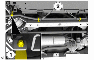
Loosen E8 bolt (1).
Release both holders (2) from the front suspension crossmember sub-assembly.
- NOTICE:
- ·
The coolant hose is not removed.
·The coolant circuit is not opened.
82161
21.SEPARATE FLOOR WIRE
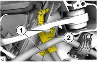
Loosen T25 screws (1).
Remove the wire harness mounting (2) with wire harness, move it to the side and secure it in place.
48630
22.REMOVE FRONT UPPER SUSPENSION ARM ASSEMBLY LH (w/ Front Suspension Member Bracket)
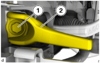
Loosen 18 mm bolt (1).
Remove the front suspension member bracket sub-assembly LH (2).
48610
23.REMOVE FRONT UPPER SUSPENSION ARM ASSEMBLY RH (w/ Front Suspension Member Bracket)
- HINT:
-
Use the same procedure as for the LH side.
51201
24.SEPARATE FRONT SUSPENSION CROSSMEMBER SUB-ASSEMBLY
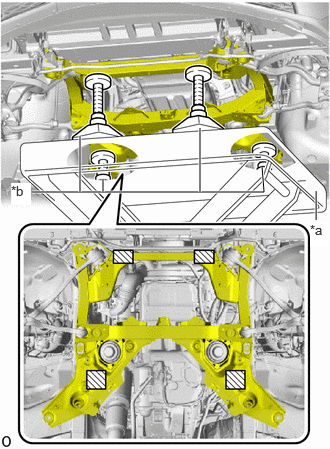
| *a | Engine Lifter |
| *b | Attachment |

|
Attachment placement location |
Support the front suspension crossmember sub-assembly with an engine lifter using 4 attachments or equivalent tools as shown in the illustration.
- CAUTION:
-
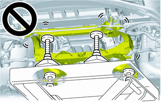
- ·
The front suspension crossmember sub-assembly is a very heavy component. Make sure that it is supported securely.
·If the front suspension crossmember sub-assembly is not securely supported, it may drop, resulting in serious injury.
- NOTICE:
-
Use attachments to keep the front suspension crossmember sub-assembly level.
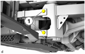
Remove the E11 bolts (1).
- HINT:
-
Perform the operations on the left and right side.
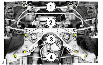
Remove the E14 bolts (1), E18 bolts (2), bolts (3) and E18 bolts (4)
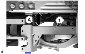
Lower the front axle support (1) by dimension (A).
Dimension (A) = maximum of 100 mm
- NOTICE:
-
When lowering the front suspension crossmember sub-assembly, be careful not to damage the vehicle body or other components installed to the vehicle.
12361
25.REMOVE FRONT ENGINE MOUNTING INSULATOR LH
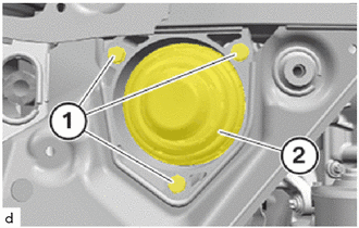
Loosen bolts (1).
Remove front engine mounting insulator LH (2).
12361
26.REMOVE FRONT ENGINE MOUNTING INSULATOR RH
- HINT:
-
Use the same procedure as for the LH side.
12315
27.REMOVE NO. 1 FRONT ENGINE MOUNTING BRACKET LH
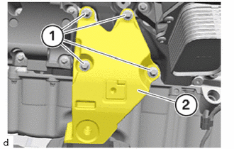
Loosen E12 bolts (1).
Remove the No. 1 front engine mounting bracket LH (2).
12311
28.REMOVE NO. 1 FRONT ENGINE MOUNTING BRACKET RH
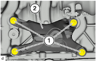
Loosen E12 bolts (1).
Remove the No. 1 front engine mounting bracket RH (2).