B58 ENGINE MECHANICAL ENGINE MOUNTING INSTALLATION
PROCEDURE

 12311
1.INSTALL NO. 1 FRONT ENGINE MOUNTING BRACKET RH
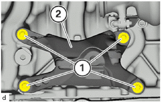
Install the No. 1 front engine mounting bracket RH (2).
Tighten the E12 bolts (1).
- Torque:
- 38 N*m (387 kgf*cm, 28 ft.*lbf)
12315
2.INSTALL NO. 1 FRONT ENGINE MOUNTING BRACKET LH
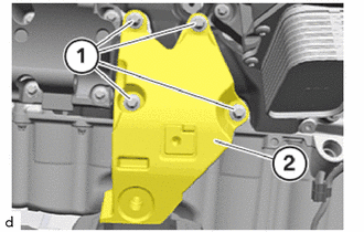
Install the No. 1 front engine mounting bracket LH (2).
Tighten the E12 bolts (1).
- Torque:
- 38 N*m (387 kgf*cm, 28 ft.*lbf)
12361
3.INSTALL FRONT ENGINE MOUNTING INSULATOR LH
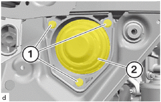
Install the front engine mounting insulator LH (2).
Tighten the bolts (1).
- Torque:
- 19 N*m (194 kgf*cm, 14 ft.*lbf)
12361
4.INSTALL FRONT ENGINE MOUNTING INSULATOR RH
- HINT:
-
Use the same procedure as for the LH side.
51201
5.INSTALL FRONT SUSPENSION CROSSMEMBER SUB-ASSEMBLY
48630
6.INSTALL FRONT UPPER SUSPENSION ARM ASSEMBLY LH (w/ Front Suspension Member Bracket)
Position front upper suspension arm assembly LH at the front suspension crossmember sub-assembly.
Replace the 18 mm bolt.
Tighten 18 mm bolt.
- Torque:
- 100 N*m (1020 kgf*cm, 74 ft.*lbf)
- NOTICE:
-
Tighten the 18 mm bolt connection in the normal position.
Using SST, tighten the 18 mm bolt an additional 90°.
- SST
- 09900-WA010
- HINT:
-
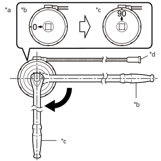 2.99,1.271 3.156,1.188 false 2.906,2.094 2.906,1.76 false 0.875,3 1.208,3 false 0.104,0.125 0.417,0.281 0.313,0.156 10 false *a 0.448,0.125 0.76,0.281 0.313,0.156 10 false *b 2.042,0.125 2.354,0.281 0.313,0.156 10 false *c 3.188,1.073 3.427,1.271 0.24,0.198 10 false *d 2.854,2.146 3.167,2.302 0.313,0.156 10 false *b 1.302,2.927 1.615,3.083 0.313,0.156 10 false *c
*a Example *b Before Tightening *c After Tightening *d Magnetic Portion
- ·
The magnetic portion is used to secure the gauge to the vehicle.
·After first adjusting the needle of the gauge to 0°, tighten to the specified angle.
·Perform the work procedure carefully so that the gauge, etc. does not become tilted.
48610
7.INSTALL FRONT UPPER SUSPENSION ARM ASSEMBLY RH (w/ Front Suspension Member Bracket)
- HINT:
-
Use the same procedure as for the LH side.
82161
8.INSTALL FLOOR WIRE
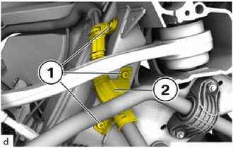
Position the wire harness mounting (2) with the wire harness.
Tighten the T25 screws (1).
- Torque:
- 8.0 N*m (82 kgf*cm, 71 in.*lbf)
9.INSTALL COOLANT HOSE
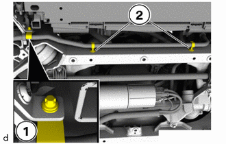
Position both holders (2) at the front suspension crossmember sub-assembly.
Tighten down E8 bolts (1).
- Torque:
- 11.8 N*m (120 kgf*cm, 9 ft.*lbf)
52822
10.INSTALL AIR INTAKE DUCT LH
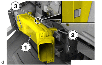
Position air intake duct LH (1) with the guide (2) correctly and clip into the latch mechanisms (3).
52821
11.INSTALL AIR INTAKE DUCT RH
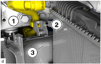
Clip in coolant line (1) with the bracket (2) in the air intake duct RH (3).
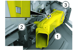
Position brake air duct RH (1) with the guide (2) correctly and clip into the latch mechanisms (3).
45220
12.INSTALL STEERING INTERMEDIATE SHAFT ASSEMBLY
13.REMOVE ENGINE SUPPORT BRIDGE
for Type A:
Click hereSuspension>FRONT SUSPENSION>FRONT SUSPENSION MEMBER>INSTALLATION
for Type B:
Click hereSuspension>FRONT SUSPENSION>FRONT SUSPENSION MEMBER>INSTALLATION
14.REMOVE ENGINE HANGER
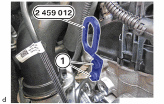
Unscrew the bolts of the special tool 2 459 012.
- SST
- 09200-WA610
Feed out the special tool 2 459 012 at the cylinder head and remove.
- SST
- 09200-WA610
25051
15.INSTALL EXHAUST MANIFOLD CONVERTER SUB-ASSEMBLY
12361
16.INSTALL FRONT ENGINE MOUNTING INSULATOR LH
- NOTICE:
-
In order to prevent play, lower the engine completely before screwing the engine mount and engine mounting bracket.
Tighten down E14 bolt.
- Torque:
- 100 N*m (1020 kgf*cm, 74 ft.*lbf)
12361
17.INSTALL FRONT ENGINE MOUNTING INSULATOR RH
- NOTICE:
-
In order to prevent play, lower the engine completely before screwing the engine mount and engine mounting bracket.
Tighten down E14 bolt.
- Torque:
- 100 N*m (1020 kgf*cm, 74 ft.*lbf)
53879
18.INSTALL FRONT FENDER LINER LH
53878
19.INSTALL FRONT FENDER LINER RH
- HINT:
-
Use the same procedure as for the LH side.
51219
20.INSTALL FRONT SUSPENSION MEMBER LOWER PROTECTOR
53826A
21.INSTALL FRONT FENDER UPPER PROTECTOR LH
53825A
22.INSTALL FRONT FENDER UPPER PROTECTOR RH
- HINT:
-
Use the same procedure as for the LH side.
23.INSTALL ENGINE ROOM ECM BOX
24.INSTALL NO. 1 INTEGRATION RELAY
12601B
25.INSTALL NO. 1 ENGINE COVER SUB-ASSEMBLY
26.REMOVE AND INSTALL BONNET HOOD SUPPORT ASSEMBLY
27.CONNECT CABLE TO NEGATIVE BATTERY TERMINAL
28.INSPECT AIRBAG FOR FUNCTION
29. START-UP OF ELECTROMECHANICAL STEERING
30.INSPECT STRAIGHT-AHEAD DRIVING POSITION OF THE STEERING WHEEL
31.INSPECT AND ADJUST FRONT WHEEL ALIGNMENT