G16E-GTS ENGINE MECHANICAL ENGINE UNIT INSTALLATION
CAUTION / NOTICE / HINT
- NOTICE:
-
This procedure includes the installation of small-head bolts. Refer to Small-Head Bolts of Basic Repair Hint to identify the small-head bolts.
-
Click hereGeneral>INTRODUCTION>REPAIR INSTRUCTION>PRECAUTION
PROCEDURE

 11336A
1.INSTALL TIMING GEAR COVER INSULATOR
Install the timing gear cover insulator to the cylinder blocke sub-assembly.
12583A
2.INSTALL NO. 3 CYLINDER BLOCK INSULATOR
Install the No. 3 cylinder block insulator to the oil pan sub-assembly.
17138
3.INSTALL INTAKE PIPE OR HOSE STAY
Install the intake pipe or hose stay to the cylinder head cover sub-aseembly with the 3 bolts.
- Torque:
- 10 N*m (102 kgf*cm, 7 ft.*lbf)
23881B
4.INSTALL FUEL HOSE BRACKET
Install the fuel hose bracket to the cylinder head cover sub-aseembly with the 2 bolts.
- Torque:
- 10 N*m (102 kgf*cm, 7 ft.*lbf)
12631A
5.INSTALL ENGINE COVER BRACKET
Install the engine cover bracket to the vacuum pump bracket with the bolt.
- Torque:
- 21 N*m (214 kgf*cm, 15 ft.*lbf)
6.INSTALL ENGINE COVER JOINT
Install the engine cover joint to the cylinder head cover sub-aseembly and vacuum pump bracket.
- Torque:
- 10 N*m (102 kgf*cm, 7 ft.*lbf)
19500
7.INSTALL IGNITION COIL ASSEMBLY
25819
8.INSTALL VACUUM REGULATING VALVE ASSEMBLY
Install the vacuum regulating valve assembly to the cylinder head cover sub-assembly with the 2 bolts.
- Torque:
- 10 N*m (102 kgf*cm, 7 ft.*lbf)
12261
9.INSTALL VENTILATION HOSE
Connect the No. 2 ventilation hose to the cylinder head cover sub-assembly and slide the clip to secure it.
Engage the clamp.
82219A
10.INSTALL SENSOR WIRE
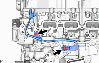
Install the sensor wire to the cylinder head sub-assembly and cylinder block sub-aseembly with the 2 bolts.
- Torque:
- Bolt (A) : 10 N*m (102 kgf*cm, 7 ft.*lbf)
- Bolt (B) : 21 N*m (214 kgf*cm, 15 ft.*lbf)
12582D
11.INSTALL NO. 2 CYLINDER BLOCK INSULATOR
Install the No. 2 cylinder block insulator to the cylinder block sub-assembly.
23255A
12.INSTALL FUEL INJECTOR SEAL
23250
13.INSTALL FUEL INJECTOR ASSEMBLY
82126A
14.INSTALL NO. 6 ENGINE WIRE
23814B
15.INSTALL FUEL DELIVERY PIPE
23100X
16.TEMPORARILY INSTALL FUEL(ENGINE ROOM SIDE) PUMP ASSEMBLY
23100X
17.INSTALL FUEL(ENGINE ROOM SIDE) PUMP ASSEMBLY
23801P
18.INSTALL NO. 1 FUEL PIPE SUB-ASSEMBLY
23291A
19.INSTALL INJECTOR VIBRATION INSULATOR
23891
20.INSTALL FUEL DELIVERY SPACER
23814B
21.INSTALL FUEL DELIVERY PIPE (for Low Pressure)
23807V
22.INSTALL NO. 1 DELIVERY PIPE SPACER
Install the No. 1 fuel delivery spacer to the cylinder head sub-asembly.
23825
23.INSTALL FUEL DELIVERY GUARD
11452D
24.INSTALL OIL LEVEL GAGE GUIDE
15301B
25.INSTALL OIL LEVEL GAGE SUB-ASSEMBLY
23902
26.INSTALL FUEL TUBE SUB-ASSEMBLY
Install the fuel tube sub-assembly
Click hereEngine / Hybrid System>G16E-GTS (FUEL)>FUEL SYSTEM>PRECAUTION
Install the bolt.
Install the fuel pipe clamp to the fuel tube connector.
82127D
27.INSTALL NO. 7 ENGINE WIRE
Connect the 2 connectors and install the No. 7 engine wire.
Engage the clamp.
28.INSTALL WATER BY-PASS PIPE
Install the water by-pass pipe to the engine assembly and slide the clip to secure it.
Install the bolt and nut.
- Torque:
- 10 N*m (102 kgf*cm, 7 ft.*lbf)
17111
29.INSTALL INTAKE MANIFOLD
17872
30.INSTALL INTAKE AIR CONNECTOR BRACKET
12632A
31.INSTALL NO. 2 ENGINE COVER BRACKET
Install the No. 2 engine cover bracket to the intake manifold with the bolt.
- Torque:
- 10 N*m (102 kgf*cm, 7 ft.*lbf)
82126A
32.INSTALL NO. 6 ENGINE WIRE
Engage the 5 clamps and connect the No. 6 engine wire.
25860
33.INSTALL PURGE VALVE (PURGE VSV)
17272
34.INSTALL NO. 2 TURBO INSULATOR
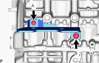
Install the No. 2 turbo insulator to the cylinder brock sub-assembly with the 2 bolts.
- Torque:
- Bolt (A) : 21 N*m (214 kgf*cm, 15 ft.*lbf)
- Bolt (B) : 30 N*m (306 kgf*cm, 22 ft.*lbf)
17201
35.INSTALL TURBOCHARGER SUB-ASSEMBLY
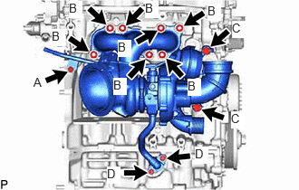
Install the turbocharger sub-aseembly to the cylinder head sub-aseembly wuth the 7 nuts.
- Torque:
- Nut (B) : 44.3 N*m (452 kgf*cm, 33 ft.*lbf)
Connect the No. 1 turbo water pipe sub-assembly with the 2 bolts.
- Torque:
- Bolt (A) : 13 N*m (133 kgf*cm, 10 ft.*lbf)
- Bolt (C) : 35 N*m (357 kgf*cm, 26 ft.*lbf)
Install the inlet turbo oil pipe union bolt.
- Torque:
- Bolt (C) : 35 N*m (357 kgf*cm, 26 ft.*lbf)
Connect the outlet turbo oil pipe with the 2 bolts.
- Torque:
- Bolt (D) : 13 N*m (133 kgf*cm, 10 ft.*lbf)
17271
36.INSTALL NO. 1 TURBO INSULATOR
12584
37.INSTALL NO. 4 CYLINDER BROCK INSULATOR
Install the No. 4 cylinder brock insulator with the 2 bolts.
- Torque:
- 10 N*m (102 kgf*cm, 7 ft.*lbf)
43457
38.INSTALL DRIVE SHAFT BEARING BRACKET
Install the drive shaft bearing bracket to the cylinder block sub-aseembly with the 3 bolts.
- Torque:
- 63.7 N*m (650 kgf*cm, 47 ft.*lbf)
12285A
39.INSTALL ENGINE HANGER BRACKET
Install the engine hanger bracket to the cylinder head sub-assembly with the 2 bolts.
- Torque:
- 43 N*m (438 kgf*cm, 32 ft.*lbf)
40.INSTALL INTAKE AIR PIPE
Install the intake air pipe and tighten the hose clamp.
Install the 3 bolts.
Connect the ventilation hose.
Connect the No. 2 vaccum transmitting hose.
Connect the No. 1 vaccum transmitting hose.
89481B
41.INSTALL DIFFERENTIAL PRESSURE SENSOR (w/ Differential Pressure Sensor)
42.INSTALL WATER BY-PASS HOSE ASSEMBLY
Install the water by-pass hose assembly and slide the clip to secure it.
Engage the clamp.
16288
43.INSTALL NO. 4 WATER BY-PASS PIPE
Install the No. 4 water by-pass pipe and slide the clip to secure it.
Connect the No. 4 water by-pass pipe with the 3 bolts.
16279
44.INSTALL NO. 3 WATER BY-PASS PIPE
Install the No. 3 water by-pass pipe and slide the clip to secure it.
Connect the No. 3 water by-pass pipe with the bolt.
- Torque:
- 10 N*m (102 kgf*cm, 7 ft.*lbf)
16268
45.INSTALL NO. 1 WATER BY-PASS PIPE
Install the No. 1 water by-pass pipe and slide the clip to secure it.
Connect the No. 1 water by-pass pipe with the bolt and nut.
- Torque:
- 10 N*m (102 kgf*cm, 7 ft.*lbf)
16284
46.INSTALL NO. 1 TURBO WATER HOSE
Install the No. 1 turbo water hose and slide the 2 clips to secure it.
44774
47.INSTALL UNION TO CONNECTOR TUBE HOSE
25781A
48.INSTALL NO. 3 VACUUM TRANSMITTING HOSE
Install the No. 3 vacuum transmitting hose.
Engage the 2 clamps.
16282
49.INSTALL NO. 5 WATER BY-PASS HOSE
Install the No. 5 water by-pass hose and slide the 2 clips to secure it.
Install the bolt.
- Torque:
- 10 N*m (102 kgf*cm, 7 ft.*lbf)
16283
50.INSTALL NO. 6 WATER BY-PASS HOSE
Install the No. 6 water by-pass hose and slide the 2 clips to secure it.
Engage the clamp.
17345F
51.INSTALL NO. 5 AIR HOSE
Install the No. 5 air hose and tighten the hose clamp.
- Torque:
- 6.0 N*m (61 kgf*cm, 53 in.*lbf)
17342D
52.INSTALL NO. 2 AIR HOSE
Install the No. 2 air hose and tighten the hose clamp.
- Torque:
- 6.0 N*m (61 kgf*cm, 53 in.*lbf)
87246
53.INSTALL OUTLET HEATER WATER HOSE
Install the outlet heater water hose and slide the clip to secure it.
87245
54.INSTALL INLET HEATER WATER HOSE
Install the inlet heater water hose and slide the clip to secure it.
23901
55.INSTALL FUEL TUBE SUB-ASSEMBLY
Install the fuel tube sub-aseembly to the fuel pipe sub-aseembly.
Click hereEngine / Hybrid System>G16E-GTS (FUEL)>FUEL SYSTEM>PRECAUTION
Engage the clamp.
88310
56.INSTALL COMPRESSOR WITH PULLEY ASSEMBLY