M15A-FXE ENGINE MECHANICAL ENGINE ASSEMBLY INSTALLATION
CAUTION / NOTICE / HINT
- CAUTION:
-
The engine assembly with transaxle is very heavy. Be sure to follow the procedure described in the repair manual, or the engine lifter may suddenly drop.
- NOTICE:
-
This procedure includes the removal of small-head bolts. Refer to Small-Head Bolts of Basic Repair Hint to identify the small-head bolts.
-
Click hereGeneral>INTRODUCTION>REPAIR INSTRUCTION>PRECAUTION
- HINT:
-
Perform "Inspection After Repair" after replacing the engine assembly.
- ·
w/ Canister Pump Module:
Click hereEngine / Hybrid System>M15A-FXE (ENGINE CONTROL)>SFI SYSTEM>INITIALIZATION
·w/o Canister Pump Module:
Click hereEngine / Hybrid System>M15A-FXE (ENGINE CONTROL)>SFI SYSTEM>INITIALIZATION
PROCEDURE

 1.INSTALL ENGINE HANGER
2.REMOVE ENGINE FROM ENGINE STAND
Remove the engine assembly from the engine stand.
88370
3.INSTALL COMPRESSOR WITH MOTOR ASSEMBLY
19315
4.INSTALL NO. 1 CRANKSHAFT POSITION SENSOR PLATE
13405
5.INSTALL FLYWHEEL SUB-ASSEMBLY
31270
6.INSTALL TRANSMISSION INPUT DAMPER ASSEMBLY
7.INSTALL ENGINE ASSEMBLY
8.INSTALL WATER HOSE
Install the water hose to the engine assembly with transaxle and slide the 3 clips to secure it.
82121
9.INSTALL ENGINE WIRE
Connect all the connectors and clamps, and install the engine wire to the engine assembly with transaxle.
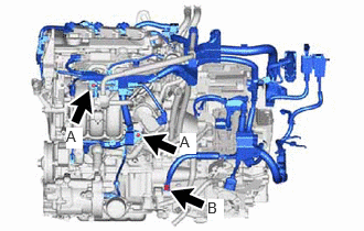
Install the 3 bolts.
- Torque:
- Bolt (A) : 10 N*m (102 kgf*cm, 7 ft.*lbf)
- Bolt (B) : 20 N*m (204 kgf*cm, 15 ft.*lbf)
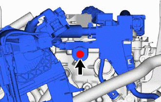
Install the bolt.
- Torque:
- 10 N*m (102 kgf*cm, 7 ft.*lbf)
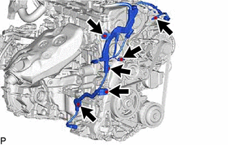
Install the 6 bolts.
- Torque:
- 10 N*m (102 kgf*cm, 7 ft.*lbf)
821H2
10.INSTALL HV AIR CONDITIONING WIRE
11363A
11.INSTALL FLYWHEEL HOUSING SIDE COVER
28193
12.INSTALL STARTER HOLE INSULATOR
12305
13.INSTALL ENGINE MOUNTING INSULATOR SUB-ASSEMBLY RH
- HINT:
-
Perform this procedure only when replacement of the engine mounting insulator sub-assembly RH is necessary.
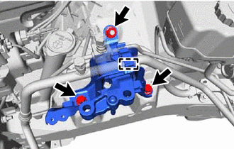
Temporarily install the engine mounting insulator sub-assembly RH to the vehicle.
Install the 2 bolts and nut in the order shown in the illustration.
- Torque:
- 72 N*m (734 kgf*cm, 53 ft.*lbf)
Engage the clamp.
G92A0A
14.INSTALL INVERTER RESERVE TANK ASSEMBLY
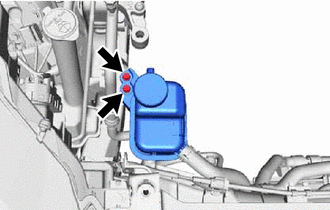
Install the inverter reserve tank assembly to the engine mounting insulator sub-assembly RH with the 2 bolts.
- Torque:
- 5.0 N*m (51 kgf*cm, 44 in.*lbf)
12372A
15.INSTALL ENGINE MOUNTING INSULATOR LH
- HINT:
-
Perform this procedure only when replacement of the engine mounting insulator LH is necessary.
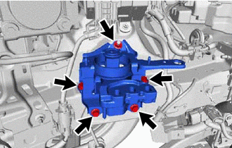
Temporarily install the engine mounting insulator LH to the vehicle.
Install the 4 bolts and nut in the order shown in the illustration.
- Torque:
- 42 N*m (428 kgf*cm, 31 ft.*lbf)
16.REMOVE ENGINE HANGER
12353
17.INSTALL ENGINE MOUNTING BRACKET CAP
Install the engine mounting bracket cap to the engine mounting bracket RH.
18.INSTALL ENGINE ASSEMBLY WITH TRANSAXLE
Using height adjustment attachments and plate lift attachments to keep the engine assembly with transaxle and front suspension crossmember sub-assembly level, set an engine lifter underneath the engine assembly with transaxle and front suspension crossmember sub-assembly.
- NOTICE:
- ·
Using height adjustment attachments and plate lift attachments, keep the engine assembly with transaxle horizontal.
·Do not perform any procedures while the engine assembly is suspended because doing so may cause the engine assembly to drop, resulting in injury. However, the engine assembly needs to be suspended when it is installed to or removed from an engine stand.
·To prevent the oil pan sub-assembly from deforming, do not place any attachments under the oil pan sub-assembly of the engine assembly with transaxle.
Operate the engine lifter and install the engine assembly with transaxle to the vehicle.
- CAUTION:
-
Do not raise the engine assembly with transaxle more than necessary. If the engine is raised excessively, the vehicle may also be lifted up.
- NOTICE:
- ·
Make sure that the engine assembly with transaxle is clear of all wiring and hoses.
·While raising the engine assembly with transaxle into the vehicle, do not allow it to contact the vehicle.
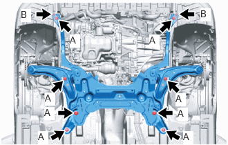
Connect the front suspension crossmember sub-assembly to the vehicle with the 10 bolts.
- Torque:
- Bolt (A) : 107.5 N*m (1096 kgf*cm, 79 ft.*lbf)
- Bolt (B) : 30 N*m (306 kgf*cm, 22 ft.*lbf)
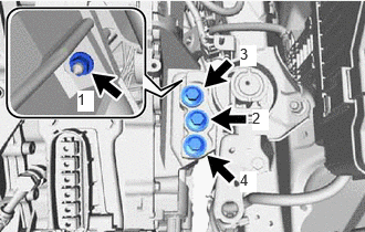
Install the engine mounting insulator LH to the engine mounting bracket LH with the 3 bolts and nut in the order shown illustration.
- Torque:
- Bolt : 42 N*m (428 kgf*cm, 31 ft.*lbf)
- Nut : 20 N*m (204 kgf*cm, 15 ft.*lbf)
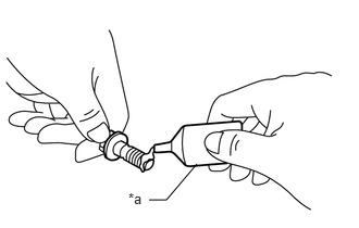
| *a | Adhesive |
Apply adhesive to the 2 or 3 threads at the tip of each of the 2 bolts.
- Adhesive:
Toyota Genuine Adhesive 1324, Three Bond 1324 or equivalent
- NOTICE:
-
To prevent contamination by foreign matter, install immediately after applying adhesive.
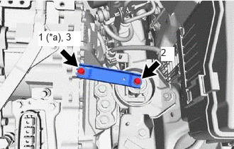
| *a | Temporarily Tighten |
Install the 2 bolts in the order shown in the illustration.
- Torque:
- 8.0 N*m (82 kgf*cm, 71 in.*lbf)
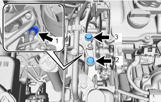
Install the engine mounting insulator sub-assembly RH to the engine mounting bracket RH with the 2 bolts and nut in the order shown illustration.
- Torque:
- Bolt : 72 N*m (734 kgf*cm, 53 ft.*lbf)
- Nut : 41 N*m (418 kgf*cm, 30 ft.*lbf)
19.INSTALL DRIVE SHAFT ASSEMBLY
for TMMF, TMMCZ Made:
17410
20.INSTALL FRONT EXHAUST PIPE ASSEMBLY
45260
21.CONNECT NO. 2 STEERING INTERMEDIATE SHAFT ASSEMBLY
45259A
22.INSTALL COLUMN HOLE COVER SILENCER SHEET (for LHD)
45259A
23.INSTALL COLUMN HOLE COVER SILENCER SHEET (for RHD)
88704
24.CONNECT SUCTION HOSE SUB-ASSEMBLY
88711
25.CONNECT NO. 1 COOLER REFRIGERANT DISCHARGE HOSE
23901
26.CONNECT FUEL TUBE SUB-ASSEMBLY
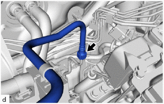
Connect the fuel tube sub-assembly to the fuel pump assembly.
Click hereEngine / Hybrid System>M15A-FXE (FUEL)>FUEL SYSTEM>PRECAUTION
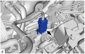
Install the No. 1 fuel pipe clamp to the fuel tube sub-assembly.
87245
27.CONNECT INLET HEATER WATER HOSE
16290F
28.CONNECT NO.3 WATER BY-PASS HOSE ASSEMBLY
77261D
29.CONNECT FUEL TANK TO CANISTER TUBE
Engage the clamp to connect the fuel tank to canister tube to the engine wire.
23826
30.CONNECT NO. 1 FUEL VAPOR FEED HOSE
Connect the No. 1 fuel vapor feed hose to the fuel tank to canister tube.
G922F
31.CONNECT OUTLET NO. 1 HYBRID WATER PUMP HOSE
Connect the outlet No. 1 hybrid water pump hose to the motor cooling cooler and slide the clip to secure it.
G922H
32.CONNECT INLET HYBRID RADIATOR HOSE
Connect the inlet hybrid radiator hose to the motor cooling cooler and slide the clip to secure it.
16572D
33.CONNECT NO. 2 RADIATOR HOSE
Connect the No. 2 radiator hose to the water inlet sub-assembly and slide the clip to secure it.
16571C
34.CONNECT NO. 1 RADIATOR HOSE
Connect the No. 1 radiator hose to the water outlet and slide the clip to secure it.
33820B
35.CONNECT TRANSMISSION CONTROL CABLE ASSEMBLY
Install the transmission control cable assembly to the hybrid vehicle transaxle assembly with the bolt.
- Torque:
- 12 N*m (122 kgf*cm, 9 ft.*lbf)
Engage the clamp to connect the transmission control cable assembly.
Install the transmission control cable assembly to the No. 1 transmission control cable bracket with a new clip.
Install the transmission control cable assembly to the control shaft lever with the nut.
- Torque:
- 12 N*m (122 kgf*cm, 9 ft.*lbf)
36.CONNECT ENGINE WIRE
Engage the clamp to connect the engine wire to the vehicle.
Connect the engine wire to the vehicle with the 2 bolts.
- Torque:
- 10 N*m (102 kgf*cm, 7 ft.*lbf)
Engage the clamp.
Engage the 4 claws to connect the engine wire to the engine room relay block.
Install the nut.
- Torque:
- 10 N*m (102 kgf*cm, 7 ft.*lbf)
Connect the 2 connectors to the engine room relay block.
82662A
37.INSTALL NO. 1 RELAY BLOCK COVER
Install the No. 1 relay block cover to the engine room relay block.
G9200
38.INSTALL INVERTER WITH CONVERTER ASSEMBLY
39.ADD ENGINE OIL
40.ADD ENGINE COOLANT (for Engine)
41.ADD HYBRID TRANSAXLE FLUID
42.CHARGE AIR CONDITIONING SYSTEM WITH REFRIGERANT
43. WARM UP COMPRESSOR
44.INSPECT HYBRID TRANSAXLE FLUID
45.INSPECT SHIFT LEVER POSITION
for TMMF, TMMCZ Made:
46.ADJUST SHIFT LEVER POSITION
47.INSPECT FOR ENGINE OIL LEAK
48.INSPECT FOR COOLANT LEAK (for Inverter)
49.INSPECT FOR COOLANT LEAK (for Engine)
50.INSPECT FOR REFRIGERANT LEAK
51.INSPECT FOR FUEL LEAK
52.INSPECT FOR EXHAUST GAS LEAK
53.CHECK ENGINE OIL LEVEL
54.INSPECT ENGINE COOLANT LEVEL IN RESERVOIR TANK
51447D
55.INSTALL CENTER NO. 4 ENGINE UNDER COVER
for TMC Made:
Click hereSuspension>FRONT SUSPENSION>FRONT SUSPENSION MEMBER (except G16E-GTS)>INSTALLATION
for TMMF, TMMCZ Made:
Click hereSuspension>FRONT SUSPENSION>FRONT SUSPENSION MEMBER (except G16E-GTS)>INSTALLATION
51442C
56.INSTALL ENGINE UNDER COVER LH
51441C
57.INSTALL ENGINE UNDER COVER RH
51451A
58.INSTALL CENTER ENGINE UNDER COVER
59.INSTALL FRONT WHEELS
60. ALIGN FRONT WHEELS FACING STRAIGHT AHEAD
61.INSPECT AND ADJUST FRONT WHEEL ALIGNMENT
62. INITIALIZATION AFTER RECONNECTING AUXILIARY BATTERY TERMINAL
Click hereGeneral>MAINTENANCE>M15A-FXE AUXILIARY BATTERY>INSTALLATION
- HINT:
-
When disconnecting and reconnecting the battery, there is an automatic learning function thatcompletes learning when the respective system is used.
-
Click hereGeneral>SETUP>WHEN DISCONNECTING OR RECONNECTING BATTERY TERMINAL>AUTOMATIC LEARNING CHART
63.INSPECT IGNITION TIMING
64.INSPECT ENGINE IDLE SPEED
65.INSPECT CO/HC
66.CHECK SPEED SENSOR SIGNAL