Valve and Cylinder Head Removal and Installation
Precautions: General safety (00)
Removal
1)Remove timing chain. 
2)Remove spark plugs.
3)Remove intake and exhaust camshafts.
4)Remove water inlet pipe No.1.
5)Disconnect PCV valve hose (1).
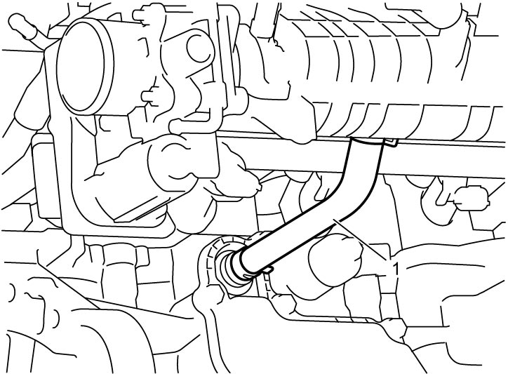

6)Remove catalytic converter.
7)Remove turbocharger.
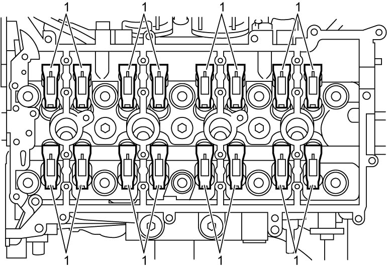
8)Remove valve rocker arms (1) from cylinder head.
9)Remove valve lash adjusters (1) from cylinder head.
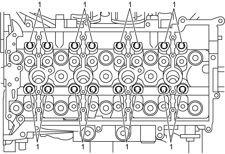
NOTE:
Immerse removed valve lash adjusters in clean engine oil and keep them as they are until their reinstallation to prevent entering of air in the adjusters.
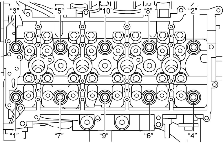
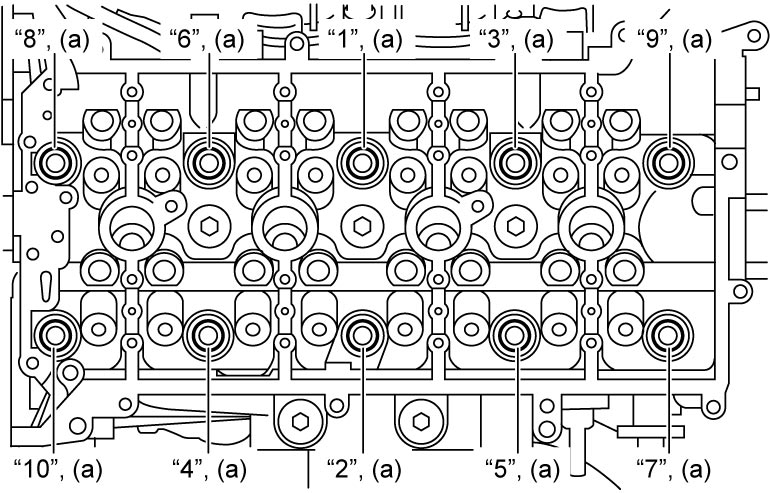
10)Remove cylinder head bolts in numerical order (“1” – “10”) evenly and gradually.
11)Check all around cylinder head for any other parts required to be removed or disconnected and remove or disconnect them if any.
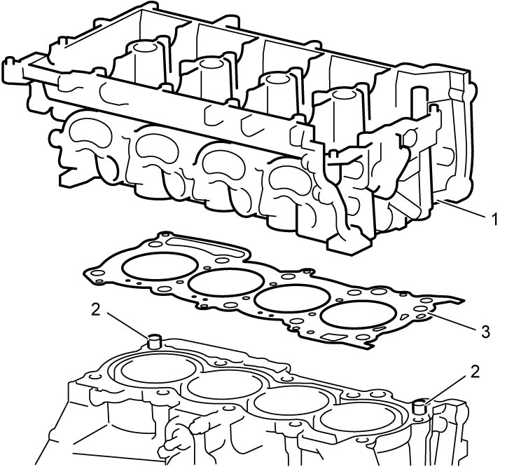
12)Remove cylinder head (1) from cylinder block.
13)Remove dowel pins (2) from cylinder block, if necessary.
14)Remove cylinder head gasket (3) from cylinder block.
15)Remove the following components from cylinder head, if necessary.
•Intake manifold:
•Fuel feed pipe (engine side)
•Fuel delivery pipe and fuel injectors:
•Fuel feed pipe (engine side)
•Fuel delivery pipe and fuel injectors:
Installation
1)Clean mating surfaces of cylinder head and cylinder block. Remove oil, old gasket and dust from mating surfaces.
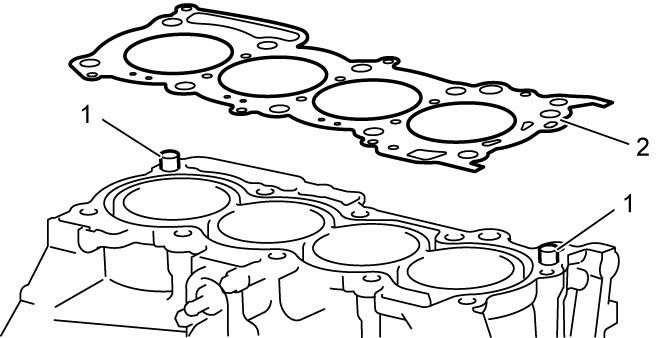
2)Install dowel pins (1) to cylinder block, if removed.
3)Set new cylinder head gasket (2) to cylinder block.
4)Install cylinder head to cylinder block according to the following procedure.
NOTE:
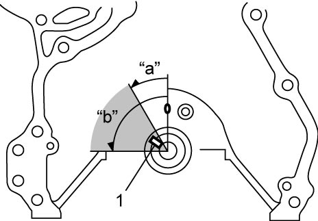
•Before installing the cylinder head to the cylinder block, turn crankshaft counterclockwise and position the key (1) within an angle of 30° – 90° from TDC as shown in figure and keep the valves from coming in contact with the piston.
•If cylinder head bolt is reused, check bolt for deformation.
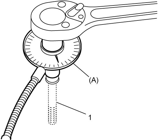
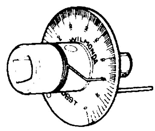
•For accurate angle tightening of cylinder head bolt (1), it is recommended to use tightening angle gauge (special tool).
| “a”: | 30° | “b”: | 90° |
•For accurate angle tightening of cylinder head bolt (1), it is recommended to use tightening angle gauge (special tool).
a)Apply engine oil to thread for 4 mm (0.15 in.) from lower end of cylinder head bolts.
b)Tighten cylinder head bolts to 15 N·m (1.5 kgf-m, 11.0 lbf-ft) in numerical order (“1” – “10”) as shown using a 12-point socket wrench.
c)In the same manner as in Step b), tighten them to 30 N·m (3.1 kgf-m, 22.5 lbf-ft).
d)Retighten all cylinder head bolts 70° in numerical order as shown in figure.
5)Install fuel injectors and fuel delivery pipe, if removed.
6)Install fuel feed pipe (engine side), if removed.
7)Install intake manifold, if removed.
8)Install turbocharger.
9)Install catalytic converter.
10)Connect PCV valve hose (1).
11)Install water inlet pipe No.1.
12)Apply engine oil to valve lash adjusters (1), and then install them to cylinder head.
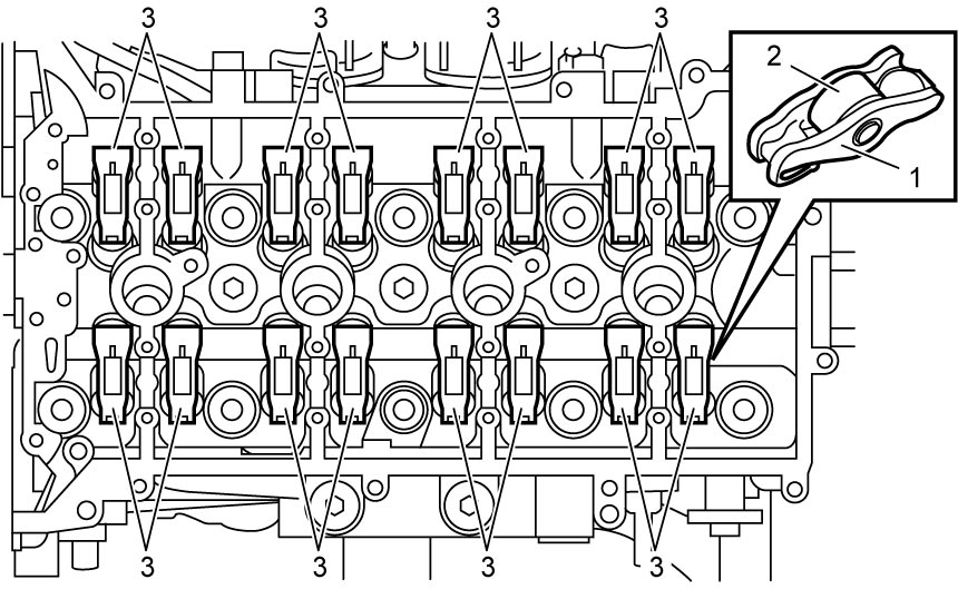
13)Apply engine oil to each of valve rocker arm body (1) and the roller (2) sufficiently, and then put the valve rocker arms (3) to cylinder head.
14)Install intake and exhaust camshafts.
15)Install spark plugs.
16)Install timing chain.
17)Install timing chain cover.
18)Install cylinder head cover.
19)Install oil pan.
20)Install engine assembly to vehicle.