HVAC Unit Removal and Installation
Precautions: General safety (00)
Removal
1)Disable air bag system. 
2)Recover refrigerant from A/C system using recovery and recycling equipment referring to “Recovery” in Operation Procedure for Refrigerant Charge:Manual Type.
3)Drain engine coolant.
•Petrol model:
•Diesel model:
•Diesel model:
4)For diesel model, remove engine cover.
5)Remove windshield wiper arms.
6)Remove cowl top garnish.
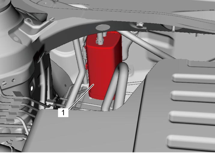
7)For LHD – petrol model, detach EVAP canister (1) from EVAP canister bracket.

8)For RHD – diesel model, remove ECM.
9)For RHD – diesel model, remove air cleaner assembly.
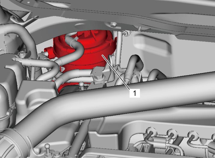
10)For diesel model, detach fuel filter (1) from fuel filter bracket.
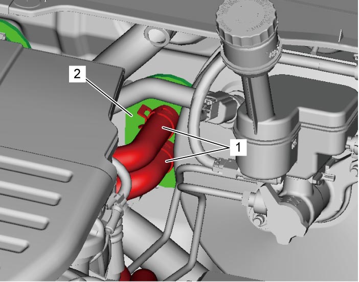
11)Disconnect heater hoses (1) from HVAC unit (2).
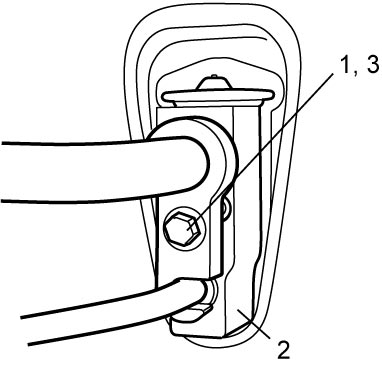
12)For HFC-134a model, remove suction pipe bolt (1), and then remove liquid pipe and suction pipe from expansion valve (2).
13)For HFO-1234yf model, remove inner heat exchanger pipe bolt (3), and then remove inner heat exchanger pipe from expansion valve.
14)Remove instrument panel from vehicle body.
15)Remove right and left rear ducts and center rear duct. (if equipped)
16)Remove HVAC unit (1) from vehicle by removing nuts (2).
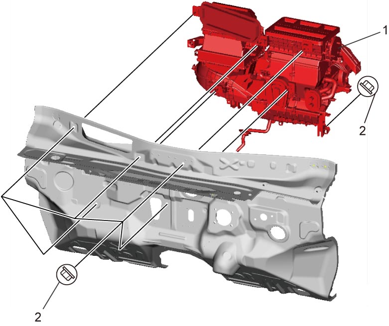
NOTE:
When removing HVAC unit, be careful not to spill engine coolant and compressor oil on vehicle floor.
Installation
Reverse removal procedure noting the following points.
•Replenish compressor with specified amount of compressor oil from compressor suction side referring to “Replenishing Compressor Oil” in Operation Procedure for Refrigerant Charge:Manual Type.
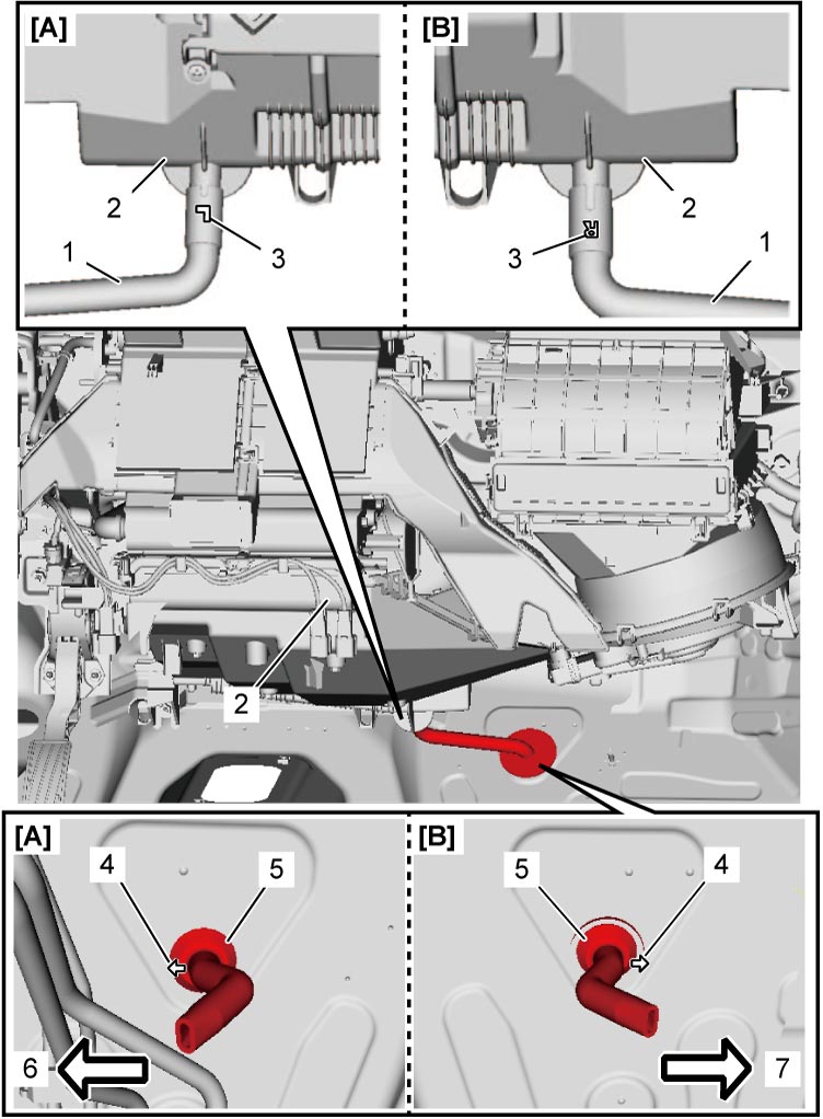
•Install drain hose (1) as follows.
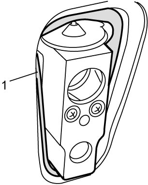 •Tighten the following bolts and nuts to specified torques.
•Refill cooling system with coolant.
•Install drain hose (1) as follows.
—Fit drain hose to HVAC (2) positioning embossed letter (3) “L” (LHD model) or “R” (RHD model) upward.
—Direct arrow mark (4) on hose grommet (5) to rightward (LHD model) or leftward (RHD model) as shown in figure.
—Fit hose grommet to dash panel hole so that lower lip of the grommet is positioned under the panel.
•Install padding (1) to installation hole uniformly.—Direct arrow mark (4) on hose grommet (5) to rightward (LHD model) or leftward (RHD model) as shown in figure.
—Fit hose grommet to dash panel hole so that lower lip of the grommet is positioned under the panel.
| [A]: | LHD model | 6. | Vehicle rightward |
| [B]: | RHD model | 7. | Vehicle leftward |
—Suction pipe bolt (HFC-134a)
—Inner heat exchanger pipe bolt (HFO-1234yf)
—HVAC unit mounting nuts
•Evacuate and charge A/C system referring to “Evacuation” and “Charge” in Operation Procedure for Refrigerant Charge:Manual Type.—Inner heat exchanger pipe bolt (HFO-1234yf)
—HVAC unit mounting nuts
•Refill cooling system with coolant.
—Petrol model:
—Diesel model:
•Adjust control cables. —Diesel model: