6AR-FSE ENGINE MECHANICAL CYLINDER HEAD GASKET INSTALLATION
CAUTION / NOTICE / HINT
- HINT:
-
Perform inspection after repair after replacing the cylinder head sub-assembly.
-
Click hereEngine / Hybrid System>6AR-FSE (ENGINE CONTROL)>SFI SYSTEM>INITIALIZATION
PROCEDURE

 11101A
1.INSPECT CYLINDER HEAD SET BOLT
11101
2.INSPECT CYLINDER HEAD SUB-ASSEMBLY
11115
3.INSTALL CYLINDER HEAD GASKET
Clean the cylinder block sub-assembly and cylinder head sub-assembly with solvent.
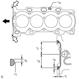
| *1 | Cylinder Head Gasket |
| *a | Lot No. |
| *b | 3.0 to 5.0 mm (0.118 to 0.197 in.) |
| *c | 152.5 mm (6.00 in.) |
| *d | 38 mm (1.50 in.) |
| *e | 7.0 to 9.0 mm (0.276 to 0.354 in.) |
| *f | 5.0 to 7.0 mm (0.197 to 0.276 in.) |

|
Front |

|
Seal Packing |
Apply a continuous line of seal packing to a new cylinder head gasket as shown in the illustration.
- Seal Packing:
Toyota Genuine Seal Packing Black, Three Bond 1207B or equivalent
- NOTICE:
- ·
Remove any oil from the contact surfaces.
·Install the cylinder head gasket within 3 minutes and tighten the bolts within 15 minutes of applying seal packing.
Place the cylinder head gasket on the cylinder block sub-assembly with the Lot No. stamp facing upward.
- NOTICE:
-
Pay attention to the installation direction.
11101
4.INSTALL CYLINDER HEAD SUB-ASSEMBLY
- HINT:
-
The cylinder head set bolts are tightened in 4 progressive steps.
Place the cylinder head sub-assembly on the cylinder block sub-assembly.
- NOTICE:
- ·
Ensure that no oil is on the contact surface of the cylinder head sub-assembly.
·Place the cylinder head sub-assembly on the cylinder block sub-assembly gently in order not to damage the cylinder head gasket with the bottom of the cylinder head sub-assembly.
Install the 10 plate washers to the 10 cylinder head set bolts.
Apply a light coat of engine oil to the threads and under the heads of the cylinder head set bolts.
Step 1:
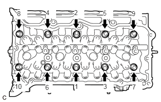
Using a 10 mm bi-hexagon wrench, install and uniformly tighten the 10 cylinder head set bolts in several steps, in the order shown in the illustration.
- Torque:
- 36 N*m (367 kgf*cm, 27 ft.*lbf)
- NOTICE:
-
Do not drop the plate washers for the cylinder head set bolts into the cylinder head sub-assembly.
Step 2:
Check that the cylinder head set bolts are tightened to the specified torque.
- Torque:
- 36 N*m (367 kgf*cm, 27 ft.*lbf)
Step 3:
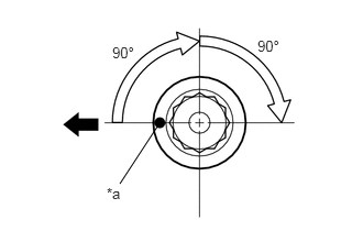
| *a | Paint Mark |
|
|
Front |
Mark each cylinder head set bolt head with paint as shown in the illustration.
Tighten the cylinder head set bolts by 90° in the order shown in step 1.
Step 4:
Tighten the cylinder head set bolts by another 90° in the order shown in step 1.
Check that the paint marks are now facing rearward.
- NOTICE:
- ·
Do not apply oil for at least 2 hours after installation.
·Do not start the engine for at least 2 hours after installation.
·After installation, if the seal packing has seeped out, wipe it off.
- HINT:
-
Perform "Inspection After Repair" after replacing the cylinder head sub-assembly.
-
Click hereEngine / Hybrid System>6AR-FSE (ENGINE CONTROL)>SFI SYSTEM>INITIALIZATION
13716
5.INSTALL VALVE STEM CAP
13750
6.INSTALL VALVE LASH ADJUSTER ASSEMBLY
13801
7.INSTALL NO. 1 VALVE ROCKER ARM SUB-ASSEMBLY
11811
8.INSTALL NO. 1 CAMSHAFT BEARING
11821
9.INSTALL NO. 2 CAMSHAFT BEARING
15678A
10.INSTALL OIL CONTROL VALVE FILTER
13511
11.INSTALL CAMSHAFT
13512
12.INSTALL NO. 2 CAMSHAFT
13.INSTALL CAMSHAFT BEARING CAP
11103
14.INSTALL CAMSHAFT HOUSING SUB-ASSEMBLY
13070A
15.INSTALL CAMSHAFT TIMING EXHAUST GEAR ASSEMBLY
13050
16.INSTALL CAMSHAFT TIMING GEAR ASSEMBLY
17.ADD ENGINE OIL
13561
18.INSTALL NO. 1 CHAIN VIBRATION DAMPER
13506
19.INSTALL CHAIN SUB-ASSEMBLY
13559
20.INSTALL CHAIN TENSIONER SLIPPER
13540
21.INSTALL NO. 1 CHAIN TENSIONER ASSEMBLY
13566B
22.INSTALL TIMING CHAIN GUIDE
23.SET NO. 1 CYLINDER TO TDC/COMPRESSION
29300
24.INSTALL VACUUM PUMP ASSEMBLY
23255A
25.INSTALL FUEL INJECTOR SEAL
23250E
26.INSTALL DIRECT FUEL INJECTOR ASSEMBLY
23807
27.INSTALL FUEL DELIVERY PIPE WITH SENSOR ASSEMBLY
82125N
28.INSTALL NO. 5 ENGINE WIRE
17111
29.INSTALL INTAKE MANIFOLD
22271
30.INSTALL THROTTLE BODY GASKET
22030
31.INSTALL THROTTLE BODY WITH MOTOR ASSEMBLY
23250F
32.INSTALL PORT FUEL INJECTOR ASSEMBLY
23291
33.INSTALL INJECTOR VIBRATION INSULATOR
23891
34.INSTALL FUEL DELIVERY SPACER
23814B
35.INSTALL FUEL DELIVERY PIPE
23901
36.CONNECT FUEL TUBE SUB-ASSEMBLY (for Port Injection)
25051
37.INSTALL EXHAUST MANIFOLD CONVERTER SUB-ASSEMBLY (TWC: Front Catalyst)
17139
38.INSTALL NO. 2 MANIFOLD STAY
17118
39.INSTALL MANIFOLD STAY
17167
40.INSTALL NO. 1 EXHAUST MANIFOLD HEAT INSULATOR
25680
41.INSTALL EGR VALVE WITH COOLER ASSEMBLY
11310
42.INSTALL TIMING CHAIN COVER SUB-ASSEMBLY