6AR-FSE ENGINE MECHANICAL ENGINE UNIT INSTALLATION
CAUTION / NOTICE / HINT
- HINT:
-
Perform "Inspection After Repair" after replacing the engine assembly.
-
Click hereEngine / Hybrid System>6AR-FSE (ENGINE CONTROL)>SFI SYSTEM>INITIALIZATION
PROCEDURE

 19500
1.INSTALL IGNITION COIL ASSEMBLY
16323
2.INSTALL WATER INLET HOUSING
- NOTICE:
-
If a stud bolt is deformed or its threads are damaged, replace it.
Using an E6 "TORX" socket wrench, install the 5 stud bolts to the water inlet housing.
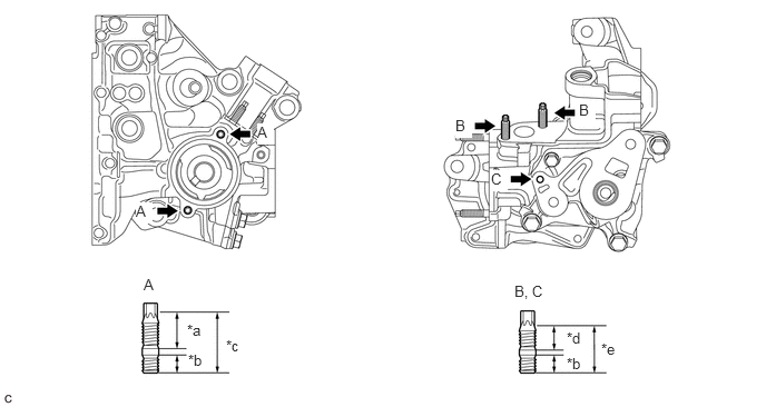
| *a | 21 mm (0.827 in.) | *b | 9.0 mm (0.354 in.) |
| *c | 34 mm (1.34 in.) | *d | 16 mm (0.630 in.) |
| *e | 27 mm (1.06 in.) | - | - |
- Torque:
- Stud Bolt (A), (B) : 4.4 N*m (45 kgf*cm, 39 in.*lbf)
- Stud Bolt (C) : 4.0 N*m (41 kgf*cm, 35 in.*lbf)
Install a new gasket to the cylinder block sub-assembly.
Install the water inlet housing to the cylinder block sub-assembly with the 4 bolts and nut.
- Torque:
- 43 N*m (438 kgf*cm, 32 ft.*lbf)
89429F
3.INSTALL ENGINE OIL TEMPERATURE SENSOR
15710
4.INSTALL OIL COOLER ASSEMBLY
16331A
5.INSTALL THERMOSTAT
16321
6.INSTALL WATER INLET
16100
7.INSTALL ENGINE WATER PUMP ASSEMBLY
8.INSTALL WIRE HARNESS CLAMP BRACKET
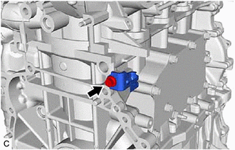
Install the wire harness clamp bracket with the bolt.
- Torque:
- 21 N*m (214 kgf*cm, 15 ft.*lbf)
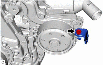
Install the wire harness clamp bracket with the bolt.
- Torque:
- 10 N*m (102 kgf*cm, 7 ft.*lbf)
16268
9.INSTALL NO. 1 WATER BY-PASS PIPE
Install a new gasket and the No. 1 water by-pass pipe with the 2 nuts and bolt.
- Torque:
- 10 N*m (102 kgf*cm, 7 ft.*lbf)
16620
10.INSTALL V-RIBBED BELT TENSIONER ASSEMBLY
Install the V-ribbed belt tensioner assembly to the water inlet housing with the bolt.
- Torque:
- 21 N*m (214 kgf*cm, 15 ft.*lbf)
Install the dust cover to the V-ribbed belt tensioner assembly.
23255A
11.INSTALL FUEL INJECTOR SEAL
23250E
12.INSTALL DIRECT FUEL INJECTOR ASSEMBLY
23807
13.INSTALL FUEL DELIVERY PIPE WITH SENSOR ASSEMBLY
82125N
14.INSTALL NO. 5 ENGINE WIRE
Engage the 2 clamps and install the No. 5 engine wire.
Connect the fuel pressure sensor connector, knock control sensor connector and 4 fuel injector set connectors.
Connect the No. 5 engine wire to the fuel delivery pipe (for Direct Injection) with the 2 bolts.
- Torque:
- 10 N*m (102 kgf*cm, 7 ft.*lbf)
17111
15.INSTALL INTAKE MANIFOLD
Install a new manifold gasket to the intake manifold.
Temporarily install the intake manifold to the cylinder head sub-assembly with the 6 bolts.
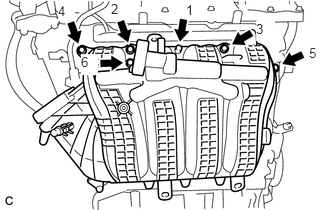
Tighten the 6 bolts in the order shown in the illustration.
- Torque:
- 28 N*m (286 kgf*cm, 21 ft.*lbf)
12262
16.CONNECT NO. 2 VENTILATION HOSE
22271
17.INSTALL THROTTLE BODY GASKET
22030
18.INSTALL THROTTLE BODY WITH MOTOR ASSEMBLY
23250F
19.INSTALL PORT FUEL INJECTOR ASSEMBLY
23291
20.INSTALL INJECTOR VIBRATION INSULATOR
23891
21.INSTALL FUEL DELIVERY SPACER
23814B
22.INSTALL FUEL DELIVERY PIPE
23901
23.CONNECT FUEL TUBE SUB-ASSEMBLY (for Port Injection)
23021
24.TEMPORARILY INSTALL FUEL PUMP WITH SEAL SUB-ASSEMBLY
23801P
25.TEMPORARILY INSTALL NO. 1 FUEL PIPE SUB-ASSEMBLY
23021
26.INSTALL FUEL PUMP WITH SEAL SUB-ASSEMBLY
23801P
27.INSTALL NO. 1 FUEL PIPE SUB-ASSEMBLY
23811B
28.INSTALL NO. 1 FUEL PIPE
29.CONNECT NO. 2 FUEL TUBE SUB-ASSEMBLY (for Direct Injection)
88431
30.INSTALL NO. 1 COMPRESSOR MOUNTING BRACKET
Install the No. 1 compressor mounting bracket with the 4 bolts.
- Torque:
- 21 N*m (214 kgf*cm, 15 ft.*lbf)
43457
31.INSTALL DRIVE SHAFT BEARING BRACKET
Install the drive shaft bearing bracket with the 3 bolts.
- Torque:
- 63.7 N*m (650 kgf*cm, 47 ft.*lbf)
- NOTICE:
-
Make sure that the bolts and bolt holes are free of oil. Clean them if necessary.
88310
32.INSTALL COMPRESSOR ASSEMBLY WITH MAGNETIC CLUTCH
for Type A:
Using an E8 "TORX" socket wrench, temporarily install the compressor assembly with magnetic clutch with the 2 stud bolts.
- Torque:
- 10 N*m (102 kgf*cm, 7 ft.*lbf)
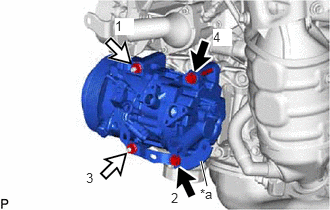
| *a | Bracket |

|
Bolt |

|
Nut |
Install the compressor assembly with magnetic clutch and bracket with the 2 bolts and 2 nuts.
- Torque:
- 24.5 N*m (250 kgf*cm, 18 ft.*lbf)
- HINT:
-
Tighten the bolts and nuts in the order shown in the illustration to install the compressor assembly with magnetic clutch.
for Type B:
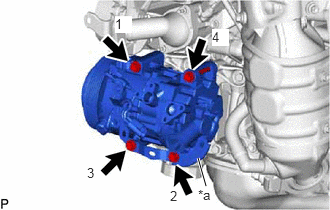
| *a | Bracket |
Install the compressor assembly with magnetic clutch and bracket with the 4 bolts.
- Torque:
- 24.5 N*m (250 kgf*cm, 18 ft.*lbf)
- HINT:
-
Tighten the bolts in the order shown in the illustration to install the compressor assembly with magnetic clutch.
33.INSTALL WIRE HARNESS CLAMP BRACKET
34.INSTALL WIRE HARNESS CLAMP BRACKET
Install the wire harness clamp bracket with the bolt.
- Torque:
- 10 N*m (102 kgf*cm, 7 ft.*lbf)
Install the wire harness clamp bracket with the bolt.
- Torque:
- 10 N*m (102 kgf*cm, 7 ft.*lbf)
Install the wire harness clamp bracket with the bolt.
- Torque:
- 10 N*m (102 kgf*cm, 7 ft.*lbf)
Install the wire harness clamp bracket with the bolt.
- Torque:
- 10 N*m (102 kgf*cm, 7 ft.*lbf)
27020
35.INSTALL GENERATOR ASSEMBLY
16361A
36.INSTALL V-RIBBED BELT
25051
37.INSTALL EXHAUST MANIFOLD CONVERTER SUB-ASSEMBLY (TWC: Front Catalyst)
Install a new exhaust manifold gasket to the cylinder head sub-assembly.
Temporarily install the exhaust manifold converter sub-assembly (TWC: Front Catalyst) to the cylinder head sub-assembly with the 5 nuts.
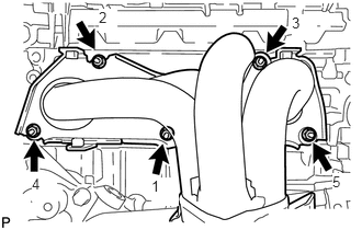
Tighten the 5 nuts in the order shown in the illustration.
- Torque:
- 62 N*m (632 kgf*cm, 46 ft.*lbf)
17139
38.INSTALL NO. 2 MANIFOLD STAY
17118
39.INSTALL MANIFOLD STAY
17167
40.INSTALL NO. 1 EXHAUST MANIFOLD HEAT INSULATOR
25680
41.INSTALL EGR VALVE WITH COOLER ASSEMBLY
42.INSTALL FUEL PUMP PROTECTOR
11452
43.INSTALL ENGINE OIL LEVEL DIPSTICK GUIDE
Apply a light coat of engine oil to a new O-ring.
Install the O-ring to the engine oil level dipstick guide.
Install the engine oil level dipstick guide with the bolt.
- Torque:
- 10 N*m (102 kgf*cm, 7 ft.*lbf)
Install the engine oil level dipstick.