2TR-FE LUBRICATION OIL PUMP REMOVAL
PROCEDURE

 1.DISCHARGE FUEL SYSTEM PRESSURE
2.DISCONNECT CABLE FROM NEGATIVE BATTERY TERMINAL
3.DRAIN ENGINE COOLANT
4.DRAIN ENGINE OIL
16400
5.REMOVE RADIATOR ASSEMBLY
17410
6.REMOVE FRONT EXHAUST PIPE ASSEMBLY
17861
7.REMOVE INTAKE AIR CONNECTOR
22030
8.REMOVE THROTTLE WITH MOTOR BODY ASSEMBLY
44360
9.SEPARATE VANE PUMP OIL RESERVOIR ASSEMBLY
44310
10.SEPARATE VANE PUMP ASSEMBLY
27020
11.REMOVE GENERATOR ASSEMBLY (for 80A Type)
27020
12.REMOVE GENERATOR ASSEMBLY (for 100A Type)
88320
13.SEPARATE COMPRESSOR AND MAGNETIC CLUTCH
44776
14.DISCONNECT BRAKE BOOSTER HOSE
87245A
15.DISCONNECT HEATER WATER HOSE INLET A
87246A
16.DISCONNECT HEATER WATER HOSE OUTLET E
23271F
17.DISCONNECT FUEL HOSE
23273C
18.DISCONNECT NO. 2 FUEL HOSE
19.REMOVE FUEL HOSE CLAMP
45450
20.SEPARATE STEERING RELAY ROD ASSEMBLY
51202
21.REMOVE NO. 2 FRAME CROSSMEMBER SUB-ASSEMBLY
33110
22.REMOVE MANUAL TRANSMISSION ASSEMBLY
23.SET ENGINE STAND
82121
24.SEPARATE ENGINE WIRE
12311
25.REMOVE NO. 1 FRONT ENGINE MOUNTING BRACKET RH
26.REMOVE ENGINE ASSEMBLY
19500
27.REMOVE IGNITION COIL ASSEMBLY
17111
28.REMOVE INTAKE MANIFOLD
16620D
29.REMOVE V-RIBBED BELT TENSIONER ASSEMBLY
16321
30.REMOVE WATER INLET
16331A
31.REMOVE THERMOSTAT
32.REMOVE HOSE CLAMP BRACKET
16603
33.REMOVE NO. 1 IDLER PULLEY SUB-ASSEMBLY
15301
34.REMOVE OIL LEVEL DIPSTICK SUB-ASSEMBLY
11452
35.REMOVE OIL LEVEL DIPSTICK GUIDE
88431
36.REMOVE NO. 1 COMPRESSOR MOUNTING BRACKET
16268
37.REMOVE NO. 1 WATER BY-PASS PIPE
Remove the 2 nuts, No. 1 water by-pass pipe and gasket.
12108
38.REMOVE OIL FILLER CAP SUB-ASSEMBLY
11201
39.REMOVE CYLINDER HEAD COVER SUB-ASSEMBLY
11301M
40.REMOVE CAMSHAFT POSITION SENSOR
13471
41.REMOVE CRANKSHAFT PULLEY
13471
42.REMOVE CRANKSHAFT PULLEY SUB-ASSEMBLY
12102A
43.REMOVE NO. 2 OIL PAN SUB-ASSEMBLY
Remove the drain plug and gasket.
Remove the 20 bolts and 2 nuts.
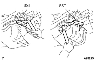
Insert the blade of SST between the oil pans. Cut through the applied sealer and remove the No. 2 oil pan sub-assembly.
- NOTICE:
-
Be careful not to damage the contact surfaces of the oil pans.
15104
44.REMOVE OIL STRAINER SUB-ASSEMBLY
Remove the bolt, 2 nuts, oil strainer sub-assembly and gasket.
12101
45.REMOVE OIL PAN SUB-ASSEMBLY
Remove the 16 bolts and 2 nuts.
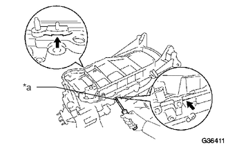
Remove the oil pan sub-assembly by prying between the oil pan sub-assembly and cylinder block with a screwdriver.
| *a | Protective Tape |
- HINT:
-
Tape the screwdriver tip before use.
- NOTICE:
-
Be careful not to damage the contact surfaces of the cylinder block and oil pan sub-assembly.
Remove the O-ring.
11301K
46.REMOVE CRANKSHAFT POSITION SENSOR
11302
47.REMOVE TIMING CHAIN OR BELT COVER SUB-ASSEMBLY
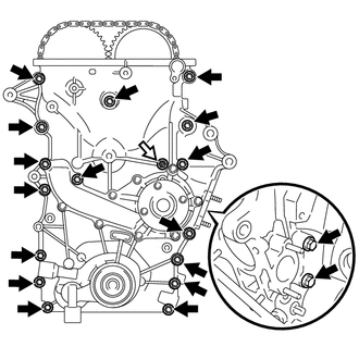
Remove the 18 bolts and the nut shown in the illustration.

|
Bolt |

|
Nut |
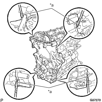
Remove the timing chain or belt cover sub-assembly by prying between the timing chain or belt cover sub-assembly and cylinder head or cylinder block with a screwdriver.
| *a | Protective Tape |
- HINT:
-
Tape the screwdriver tip before use.
- NOTICE:
-
Be careful not to damage the contact surfaces of the cylinder head, cylinder block and timing chain or belt cover sub-assembly.
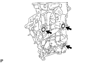
Remove the 3 O-rings.
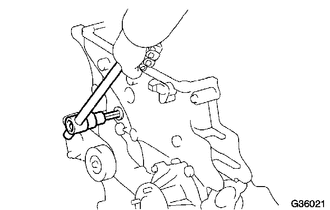
Using a 10 mm socket hexagon wrench, remove the timing chain cover plug.
16100
48.REMOVE WATER PUMP ASSEMBLY
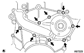
Remove the 8 bolts, water pump assembly and gasket.
11301C
49.REMOVE TIMING GEAR CASE OR TIMING CHAIN CASE OIL SEAL
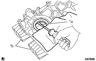
Using a screwdriver with its tip taped, pry out the timing gear case or timing chain case oil seal.
| *a | Protective Tape |
| *b | Wooden Block |