3UR-FE ENGINE MECHANICAL CAMSHAFT REMOVAL
PROCEDURE

 1.DISCHARGE FUEL SYSTEM PRESSURE
2. PRECAUTION
- NOTICE:
-
After turning the engine switch off, waiting time may be required before disconnecting the cable from the battery terminal. Therefore, make sure to read the disconnecting the cable from the battery terminal notice before proceeding with work (See page General>INTRODUCTION>REPAIR INSTRUCTION>PRECAUTION).
3.DISCONNECT CABLE FROM NEGATIVE BATTERY TERMINAL
- NOTICE:
-
When disconnecting the cable, some systems need to be initialized after the cable is reconnected (See page General>INTRODUCTION>REPAIR INSTRUCTION>INITIALIZATION).
52119A
4.REMOVE FRONT BUMPER COVER
32917
5.REMOVE TRANSMISSION OIL COOLER AIR DUCT
53294C
6.REMOVE RADIATOR SIDE DEFLECTOR LH
53883F
7.REMOVE FRONT FENDER MAIN SEAL LH
53882H
8.REMOVE FRONT FENDER MAIN SEAL RH
85221B
9.REMOVE FRONT WIPER ARM LH
85211B
10.REMOVE FRONT WIPER ARM RH
53383
11.REMOVE HOOD TO COWL TOP SEAL
55781E
12.REMOVE COWL TOP VENTILATOR LOUVER SUB-ASSEMBLY
51405C
13.REMOVE NO. 1 ENGINE UNDER COVER SUB-ASSEMBLY
51442
14.REMOVE NO. 2 ENGINE UNDER COVER
53737B
15.REMOVE FRONT FENDER APRON SEAL LH
53736G
16.REMOVE FRONT FENDER APRON SEAL FRONT RH
17.DRAIN ENGINE OIL
18.DRAIN ENGINE COOLANT
11209
19.REMOVE V-BANK COVER SUB-ASSEMBLY
17880
20.REMOVE AIR CLEANER HOSE ASSEMBLY
17700
21.REMOVE AIR CLEANER ASSEMBLY
16571C
22.REMOVE NO. 1 RADIATOR HOSE
16572D
23.REMOVE NO. 2 RADIATOR HOSE
16711
24.REMOVE FAN SHROUD
16400
25.REMOVE RADIATOR ASSEMBLY
26.DISCONNECT ENGINE WIRE
27.DISCONNECT AIR PUMP HOSE AND WIRE HARNESS (w/ Secondary Air Injection System)
28.DISCONNECT WATER PIPE AND HOSE SUB-ASSEMBLY
88320
29.DISCONNECT COOLER COMPRESSOR ASSEMBLY
23902
30.DISCONNECT NO. 2 FUEL TUBE SUB-ASSEMBLY
31.REMOVE OIL FILTER ELEMENT
11452
32.REMOVE ENGINE OIL LEVEL DIPSTICK GUIDE
83520
33.REMOVE OIL PRESSURE SENDER GAUGE ASSEMBLY
16207
34.REMOVE NO. 2 WATER BY-PASS PIPE SUB-ASSEMBLY
15781
35.REMOVE NO. 1 OIL COOLER BRACKET
15671
36.REMOVE OIL FILTER BRACKET
17111
37.REMOVE INTAKE MANIFOLD
44310
38.DISCONNECT VANE PUMP ASSEMBLY
32907A
39.DISCONNECT OIL COOLER PIPE ASSEMBLY
27020
40.REMOVE GENERATOR ASSEMBLY
16261G
41.REMOVE NO. 1 WATER BY-PASS HOSE
16206
42.REMOVE WATER BY-PASS PIPE SUB-ASSEMBLY
16355
43.REMOVE FRONT WATER BY-PASS JOINT
11212
44.REMOVE NO. 2 ENGINE COVER
12611
45.REMOVE NO. 1 ENGINE COVER
17303
46.REMOVE AIR PIPE SUB-ASSEMBLY (w/ Secondary Air Injection System)
16323
47.REMOVE WATER INLET HOUSING
16173
48.REMOVE WATER PUMP PULLEY
16603
49.REMOVE NO. 1 IDLER PULLEY SUB-ASSEMBLY
16211
50.REMOVE FLUID COUPLING BRACKET
16620
51.REMOVE V-RIBBED BELT TENSIONER ASSEMBLY
19500
52.REMOVE IGNITION COIL ASSEMBLY
11202
53.REMOVE CYLINDER HEAD COVER SUB-ASSEMBLY LH
11201
54.REMOVE CYLINDER HEAD COVER SUB-ASSEMBLY RH
11193
55.REMOVE SPARK PLUG TUBE GASKET
13471
56.REMOVE CRANKSHAFT PULLEY
57.DISCONNECT WIRE HARNESS CLAMP BRACKET
11302
58.REMOVE TIMING CHAIN COVER SUB-ASSEMBLY
16322
59.REMOVE WATER INLET PIPE
60.SET NO. 1 CYLINDER TO TDC/COMPRESSION
13540
61.REMOVE NO. 1 CHAIN TENSIONER ASSEMBLY LH
13559
62.REMOVE NO. 1 CHAIN TENSIONER SLIPPER LH
13561
63.REMOVE NO. 1 CHAIN VIBRATION DAMPER LH
13506
64.REMOVE NO. 1 CHAIN SUB-ASSEMBLY LH
13560A
65.REMOVE NO. 3 CHAIN TENSIONER ASSEMBLY
13540
66.REMOVE NO. 1 CHAIN TENSIONER ASSEMBLY RH
13559
67.REMOVE NO. 1 CHAIN TENSIONER SLIPPER RH
13561
68.REMOVE NO. 1 CHAIN VIBRATION DAMPER RH
13506
69.REMOVE NO. 1 CHAIN SUB-ASSEMBLY RH
13550
70.REMOVE NO. 2 CHAIN TENSIONER ASSEMBLY
13521A
71.REMOVE CRANKSHAFT TIMING GEAR KEY
72.REMOVE CAMSHAFT BEARING CAP LH
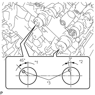
Make sure that the knock pin of the camshaft is positioned as shown in the illustration.
| *1 | IN |
| *2 | EX |
| *3 | Knock Pin |
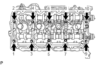
Uniformly loosen and remove the 10 bearing cap bolts in the sequence shown in the illustration.
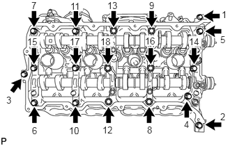
Uniformly loosen and remove the 18 bearing cap bolts in the sequence shown in the illustration.
- NOTICE:
-
Uniformly loosen the bolts while keeping the camshaft level.
Remove the 6 bearing caps.
- HINT:
-
Arrange the removed parts in the correct order.
Remove the No. 3 and No. 4 camshafts.
- HINT:
-
Arrange the removed parts in the correct order.
11104A
73.REMOVE CAMSHAFT HOUSING SUB-ASSEMBLY LH
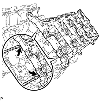
Remove the camshaft housing by prying between the cylinder head and camshaft housing with a screwdriver.
- NOTICE:
-
Be careful not to damage the contact surfaces of the cylinder head and camshaft housing.
- HINT:
-
Tape the screwdriver tip before use.
74.REMOVE CAMSHAFT BEARING CAP RH
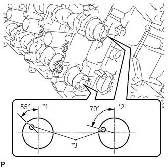
Make sure that the knock pin of the camshaft is positioned as shown in the illustration.
| *1 | EX |
| *2 | IN |
| *3 | Knock Pin |
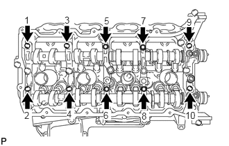
Uniformly loosen and remove the 10 bearing cap bolts in the sequence shown in the illustration.
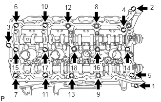
Uniformly loosen and remove the 18 bearing cap bolts in the sequence shown in the illustration.
- NOTICE:
-
Uniformly loosen the bolts while keeping the camshaft level.
Remove the 6 bearing caps.
- HINT:
-
Arrange the removed parts in the correct order.
Remove the No. 1 and No. 2 camshafts.
- HINT:
-
Arrange the removed parts in the correct order.
11103C
75.REMOVE CAMSHAFT HOUSING SUB-ASSEMBLY RH
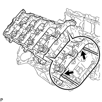
Remove the camshaft housing by prying between the cylinder head and camshaft housing with a screwdriver.
- NOTICE:
-
Be careful not to damage the contact surfaces of the cylinder head and camshaft housing.
- HINT:
-
Tape the screwdriver tip before use.