HEATING / AIR CONDITIONING REAR AIR CONDITIONING UNIT INSTALLATION
CAUTION / NOTICE / HINT
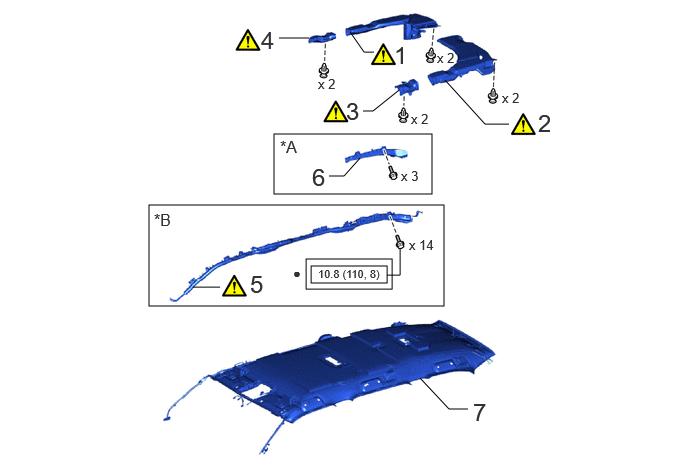
| Procedure | Part Name Code |

|

|

|
|
|---|---|---|---|---|---|
| 1 | REAR NO. 1 ROOF AIR DUCT | 88566R | ( ) |
- | - |
| 2 | REAR NO. 3 ROOF AIR DUCT | 88566T | () |
- | - |
| 3 | REAR NO. 4 ROOF AIR DUCT | 88566U | () |
- | - |
| 4 | REAR NO. 2 ROOF AIR DUCT | 88566S | () |
- | - |
| 5 | CURTAIN SHIELD AIRBAG ASSEMBLY RH | 62170A | () |
- | - |
| 6 | NO. 2 ROOF SIDE INNER GARNISH SPACER RH | 62495B | - | - | - |
| 7 | ROOF HEADLINING ASSEMBLY | - | - | - | - |
| *A | w/ Spacer | *B | w/ Rear No. 2 Seat, Curtain Shield Airbag |

|
Tightening torque for "Major areas involving basic vehicle performance such as moving/turning/stopping": N*m (kgf*cm, ft.*lbf) | ● | Non-reusable part |
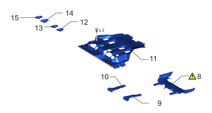
| Procedure | Part Name Code |
|
|
|
|
|---|---|---|---|---|---|
| 8 | REAR NO. 7 AIR DUCT | 87212L | () |
- | - |
| 9 | REAR NO. 6 SIDE AIR DUCT | 87217K | - | - | - |
| 10 | REAR NO. 4 SIDE AIR DUCT | 87217G | - | - | - |
| 11 | FRONT FLOOR CARPET ASSEMBLY | 58510D | - | - | - |
| 12 | REAR NO. 4 SEAT PROTECTOR | 71F95 | - | - | - |
| 13 | REAR NO. 3 SEAT PROTECTOR | 71695Y | - | - | - |
| 14 | REAR NO. 2 SEAT PROTECTOR | 71695T | - | - | - |
| 15 | REAR NO. 1 SEAT PROTECTOR | 71695S | - | - | - |
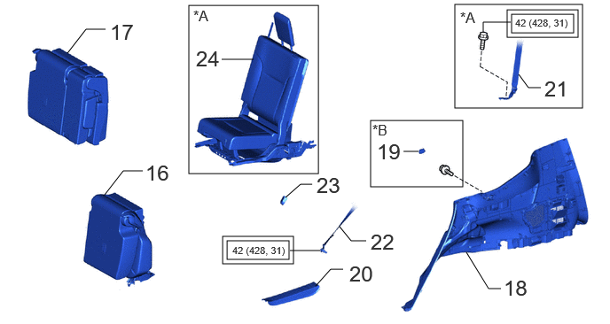
| Procedure | Part Name Code |
|
|
|
|
|---|---|---|---|---|---|
| 16 | REAR NO. 1 SEAT ASSEMBLY LH | - | - | - | - |
| 17 | REAR NO. 1 SEAT ASSEMBLY RH | - | - | - | - |
| 18 | QUARTER TRIM PANEL ASSEMBLY LH | 62520B | - | - | - |
| 19 | NO. 1 TONNEAU COVER HOLDER CAP | 64937A | - | - | - |
| 20 | REAR DOOR SCUFF PLATE LH | 67918D | - | - | - |
| 21 | REAR NO. 2 SEAT OUTER BELT ASSEMBLY LH (FLOOR ANCHOR) | 73570 | - | - | - |
| 22 | REAR NO. 1 SEAT OUTER BELT ASSEMBLY LH (FLOOR ANCHOR) | 73370C | - | - | - |
| 23 | OUTER LAP BELT ANCHOR COVER | 73233 | - | - | - |
| 24 | REAR NO. 2 SEAT ASSEMBLY LH | - | - | - | - |
| *A | w/ Rear No. 2 Seat | *B | w/ Tonneau Cover |
|
|
Tightening torque for "Major areas involving basic vehicle performance such as moving/turning/stopping": N*m (kgf*cm, ft.*lbf) | - | - |
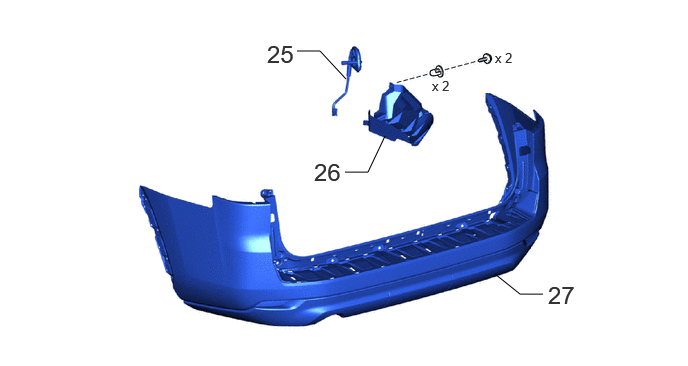
| Procedure | Part Name Code |
|
|
|
|
|---|---|---|---|---|---|
| 25 | NO. 4 COOLER UNIT DRAIN HOSE | 88539N | - | - | - |
| 26 | NO. 1 LUGGAGE COMPARTMENT SIDE COVER PROTECTOR | 58723B | - | - | - |
| 27 | REAR BUMPER ASSEMBLY | - | - | - | - |
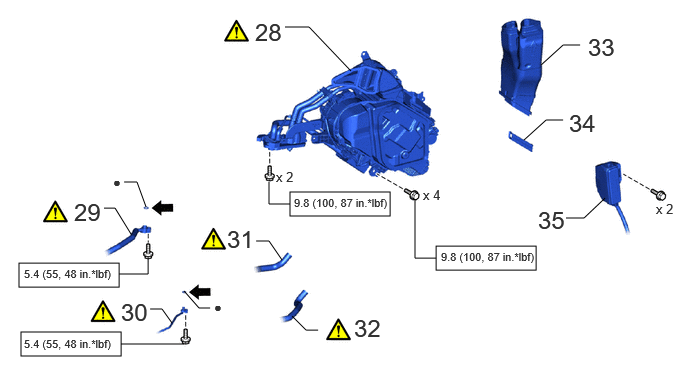
| Procedure | Part Name Code |
|
|
|
|
|---|---|---|---|---|---|
| 28 | AIR CONDITIONING BLOWER ASSEMBLY | 87030 | () |
- | - |
| 29 | NO. 2 SUCTION TUBE | 88717Z | () |
- | - |
| 30 | NO. 2 LIQUID TUBE | 88G16N | () |
- | - |
| 31 | OUTLET HEATER WATER HOSE G | 87246G | () |
- | - |
| 32 | INLET HEATER WATER HOSE H | 87245H | () |
- | - |
| 33 | REAR NO. 9 SIDE AIR DUCT | 87217N | - | - | - |
| 34 | COOLER PLATE | - | - | - | - |
| 35 | FLOOR WIRE | 82161 | - | - | - |

|
N*m (kgf*cm, ft.*lbf): Specified torque | ● | Non-reusable part |

|
Compressor oil ND-OIL 8 or equivalent | - | - |
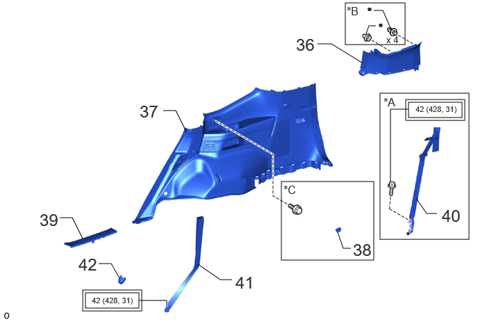
| Procedure | Part Name Code |
|
|
|
|
|---|---|---|---|---|---|
| 36 | INNER ROOF SIDE GARNISH RH | 62471A | - | - | - |
| 37 | QUARTER TRIM PANEL ASSEMBLY RH | 62510M | - | - | - |
| 38 | NO. 1 TONNEAU COVER HOLDER CAP | 64937A | - | - | - |
| 39 | REAR DOOR SCUFF PLATE RH | 67917C | - | - | - |
| 40 | REAR NO. 2 SEAT OUTER BELT ASSEMBLY RH (FLOOR ANCHOR) | 73560 | - | - | - |
| 41 | REAR NO. 1 SEAT OUTER BELT ASSEMBLY RH (FLOOR ANCHOR) | 73360C | - | - | - |
| 42 | OUTER LAP BELT ANCHOR COVER | 73233 | - | - | - |
| *A | w/ Rear No. 2 Seat | *B | w/ Rear No. 2 Seat, Curtain Shield Airbag |
| *C | w/ Tonneau Cover | - | - |
|
|
Tightening torque for "Major areas involving basic vehicle performance such as moving/turning/stopping": N*m (kgf*cm, ft.*lbf) | ● | Non-reusable part |
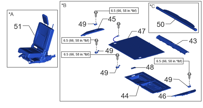
| Procedure | Part Name Code |
|
|
|
|
|---|---|---|---|---|---|
| 43 | REAR FLOOR MAT REAR SUPPORT PLATE | 58574G | - | - | - |
| 44 | REAR DECK FLOOR BOX | 64993 | - | - | - |
| 45 | REAR FLOOR BOARD REAR RH | 58417B | - | - | - |
| 46 | REAR FLOOR BOARD REAR LH | 58418H | - | - | - |
| 47 | DECK BOARD ASSEMBLY | 58410B | - | - | - |
| 48 | REAR DECK TRIM COVER | 64716P | - | - | - |
| 49 | ROPE HOOK ASSEMBLY | 66310N | - | - | - |
| 50 | TONNEAU COVER ASSEMBLY | 64910M | - | - | - |
| 51 | REAR NO. 2 SEAT ASSEMBLY RH | - | - | - | - |
| *A | w/ Rear No. 2 Seat | *B | w/o Rear No. 2 Seat |
| *C | w/ Tonneau Cover | - | - |
|
|
N*m (kgf*cm, ft.*lbf): Specified torque | - | - |
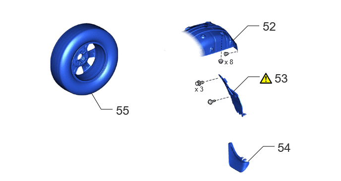
| Procedure | Part Name Code |
|
|
|
|
|---|---|---|---|---|---|
| 52 | REAR WHEEL HOUSE LINER RH | 65637B | - | - | - |
| 53 | REAR BUMPER SIDE SEAL RH | 52591 | () |
- | - |
| 54 | QUARTER PANEL REAR MUDGUARD RH | 76625G | - | - | - |
| 55 | WHEEL ASSEMBLY | - | - | - | - |
| Procedure | Part Name Code |
|
|
|
|
|---|---|---|---|---|---|
| 56 | ADD ENGINE COOLANT | - | - | () |
- |
| 57 | CHARGE AIR CONDITIONING SYSTEM WITH REFRIGERANT | - | () |
- | - |
| 58 | INSPECT FOR COOLANT LEAK | - | () |
- | - |
| 59 | WARM UP ENGINE | - | () |
- | - |
| 60 | INSPECT FOR REFRIGERANT LEAK | - | () |
- | - |
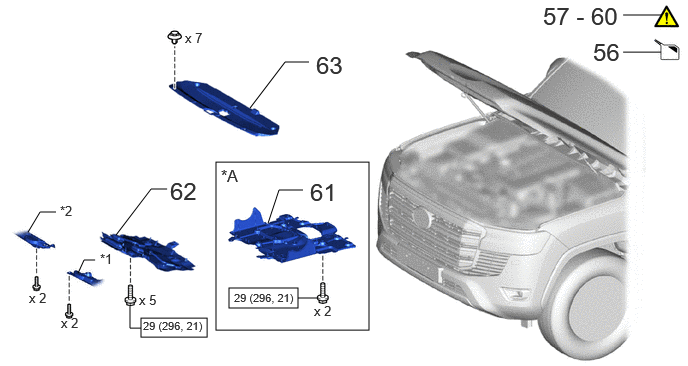
| 61 | NO. 2 ENGINE UNDER COVER ASSEMBLY | 51420 | - | - | - |
| 62 | NO. 1 ENGINE UNDER COVER ASSEMBLY | 51410 | - | - | - |
| 63 | UPPER RADIATOR SUPPORT SEAL | 53292A | - | - | - |
| *A | for 1GR-FE | - | - |
| *1 | ENGINE SIDE COVER SUB-ASSEMBLY LH | *2 | ENGINE SIDE COVER SUB-ASSEMBLY RH |
|
|
N*m (kgf*cm, ft.*lbf): Specified torque | - | - |
CAUTION / NOTICE / HINT
- HINT:
-
A bolt without a torque specification is shown in the standard bolt chart.
-
Click hereGeneral>SPECIFICATIONS>STANDARD BOLT>SPECIFIED TORQUE FOR STANDARD BOLTS
PROCEDURE

 88566R 1.INSTALL REAR NO. 1 ROOF AIR DUCT
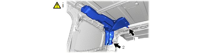
Install the rear No. 1 roof air duct with the 2 clips in the order shown in the illustration.
88566T 2.INSTALL REAR NO. 3 ROOF AIR DUCT

Install the rear No. 3 roof air duct with the 2 clips in the order shown in the illustration.
88566U 3.INSTALL REAR NO. 4 ROOF AIR DUCT
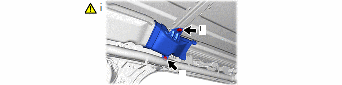
Install the rear No. 4 roof air duct with the 2 clips in the order shown in the illustration.
88566S 4.INSTALL REAR NO. 2 ROOF AIR DUCT
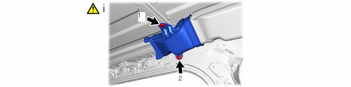
Install the rear No. 2 roof air duct with the 2 clips in the order shown in the illustration.
62170A 5.INSTALL CURTAIN SHIELD AIRBAG ASSEMBLY RH (w/ Rear No. 2 Seat, Curtain Shield Airbag)
Use the same procedure described for the LH side.
Click hereVehicle Interior>SUPPLEMENTAL RESTRAINT SYSTEMS>CURTAIN SHIELD AIRBAG ASSEMBLY>INSTALLATION
62495B 6.INSTALL NO. 2 ROOF SIDE INNER GARNISH SPACER RH (w/ Spacer)
7.INSTALL ROOF HEADLINING ASSEMBLY
87212L 8.INSTALL REAR NO. 7 AIR DUCT
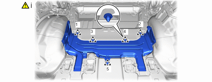
Attach the clip and install the rear No. 7 air duct in the order shown in the illustration.
87217K 9.INSTALL REAR NO. 6 SIDE AIR DUCT
87217G 10.INSTALL REAR NO. 4 SIDE AIR DUCT
58510D 11.INSTALL FRONT FLOOR CARPET ASSEMBLY
71F95 12.INSTALL REAR NO. 4 SEAT PROTECTOR
71695Y 13.INSTALL REAR NO. 3 SEAT PROTECTOR
71695T 14.INSTALL REAR NO. 2 SEAT PROTECTOR
71695S 15.INSTALL REAR NO. 1 SEAT PROTECTOR
16.INSTALL REAR NO. 1 SEAT ASSEMBLY LH
17.INSTALL REAR NO. 1 SEAT ASSEMBLY RH
for 60/40 Split Seat Type RH Side:
Click hereVehicle Interior>SEAT>REAR NO. 1 SEAT ASSEMBLY (for 60/40 Split Seat Type RH Side)>INSTALLATION
for 40/20/40 Split Seat Type RH Side:
Click hereVehicle Interior>SEAT>REAR NO. 1 SEAT ASSEMBLY (for 40/20/40 Split Seat Type RH Side)>INSTALLATION
62520B 18.INSTALL QUARTER TRIM PANEL ASSEMBLY LH
64937A 19.INSTALL NO. 1 TONNEAU COVER HOLDER CAP (w/ Tonneau Cover)
67918D 20.INSTALL REAR DOOR SCUFF PLATE LH
73570 21.INSTALL REAR NO. 2 SEAT OUTER BELT ASSEMBLY LH (FLOOR ANCHOR) (w/ Rear No. 2 Seat)
73370C 22.INSTALL REAR NO. 1 SEAT OUTER BELT ASSEMBLY LH (FLOOR ANCHOR)
73233 23.INSTALL OUTER LAP BELT ANCHOR COVER
24.INSTALL REAR NO. 2 SEAT ASSEMBLY LH (w/ Rear No. 2 Seat)
for Manual Seat:
Click hereVehicle Interior>SEAT>REAR NO. 2 SEAT ASSEMBLY (for Manual Seat)>INSTALLATION
for Power Seat:
Click hereVehicle Interior>SEAT>REAR NO. 2 SEAT ASSEMBLY (for Power Seat)>INSTALLATION
88539N 25.INSTALL NO. 4 COOLER UNIT DRAIN HOSE
58723B 26.INSTALL NO. 1 LUGGAGE COMPARTMENT SIDE COVER PROTECTOR
27.INSTALL REAR BUMPER ASSEMBLY
for Standard:
Click hereVehicle Exterior>EXTERIOR PANELS / TRIM>REAR BUMPER (for Standard)>INSTALLATION
for Aero Type:
Click hereVehicle Exterior>EXTERIOR PANELS / TRIM>REAR BUMPER (for Aero Type)>INSTALLATION
87030 28.INSTALL AIR CONDITIONING BLOWER ASSEMBLY
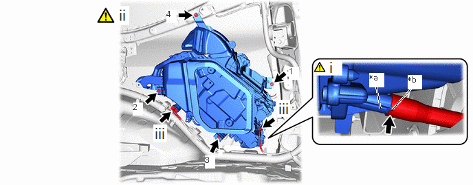
| *a | Protrusion | *b | Cutout |
Align the cutout of the No. 2 cooler unit drain hose with the protrusion of the air conditioning blower assembly and install the No. 2 cooler unit drain hose.
Install the air conditioning blower assembly with the 4 bolts and tighten the bolts in the order shown in the illustration.
- Torque:
- 9.8 N*m (100 kgf*cm, 87 in.*lbf)
Connect the 2 connectors.
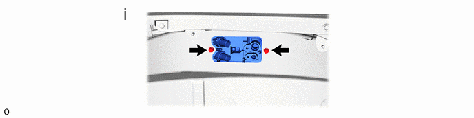
Install the 2 bolts.
- Torque:
- 9.8 N*m (100 kgf*cm, 87 in.*lbf)
88717Z 29.CONNECT NO. 2 SUCTION TUBE
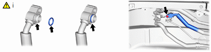
Connect the No. 2 suction tube using the following procedure.
1. Remove the vinyl tape from the No. 2 suction tube and then apply a sufficient amount of compressor oil to new O-rings and the fitting surface of the No. 2 suction tube and air conditioning blower assembly.
- Compressor Oil:
-
ND-OIL 8 or equivalent
2. Install the O-ring to the No. 2 suction tube.
- NOTICE:
-
Keep the O-rings and O-ring fitting surfaces free of foreign matter.
3. Connect the No. 2 suction tube with the bolt.
- Torque:
- 5.4 N*m (55 kgf*cm, 48 in.*lbf)
- NOTICE:
-
Make sure not to cut the O-ring while installing it. (Cut O-rings cannot be installed.)
88G16N 30.CONNECT NO. 2 LIQUID TUBE
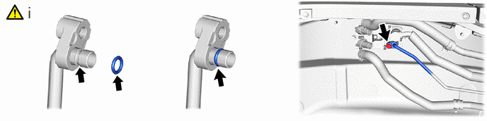
Connect the No. 2 liquid tube using the following procedure.
1. Remove the vinyl tape from the No. 2 liquid tube and then apply a sufficient amount of compressor oil to new O-rings and the fitting surface of the No. 2 liquid tube and air conditioning blower assembly.
- Compressor Oil:
-
ND-OIL 8 or equivalent
2. Install the O-ring to the No. 2 liquid tube.
- NOTICE:
-
Keep the O-rings and O-ring fitting surfaces free of foreign matter.
- Torque:
- 5.4 N*m (55 kgf*cm, 48 in.*lbf)
3. Connect the No. 2 liquid tube with the bolt.
- NOTICE:
-
Make sure not to cut the O-ring while installing it. (Cut O-rings cannot be installed.)
87246G 31.CONNECT OUTLET HEATER WATER HOSE G
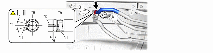
| *a | View A | *b | View B |
| *c | Positioning Rib | *d | Marking |
| *e | Hose Clip Installation Range (0 to 3 mm (0 to 0.118 in.)) | *f | Hose Clip Installation Angle (60°) |
Align the marking of the outlet heater water hose G with the positioning rib of the air conditioning blower assembly and connect the outlet heater water hose G.
- NOTICE:
-
Do not apply excessive force to the outlet heater water hose G.
Install the hose clip within the range shown in the illustration.
87245H 32.CONNECT INLET HEATER WATER HOSE H
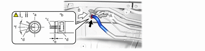
| *a | View A | *b | View B |
| *c | Positioning Rib | *d | Marking |
| *e | Hose Clip Installation Range (0 to 3 mm (0 to 0.118 in.)) | *f | Hose Clip Installation Angle (60°) |
Align the marking of the inlet heater water hose H with the positioning rib of the air conditioning blower assembly and connect the inlet heater water hose H.
- NOTICE:
-
Do not apply excessive force to the inlet heater water hose H.
Install the hose clip within the range shown in the illustration.
87217N 33.INSTALL REAR NO. 9 SIDE AIR DUCT
34.INSTALL COOLER PLATE
82161 35.CONNECT FLOOR WIRE
62471A 36.INSTALL INNER ROOF SIDE GARNISH RH
62510M 37.INSTALL QUARTER TRIM PANEL ASSEMBLY RH
64937A 38.INSTALL NO. 1 TONNEAU COVER HOLDER CAP (w/ Tonneau Cover)
67917C 39.INSTALL REAR DOOR SCUFF PLATE RH
73560 40.INSTALL REAR NO. 2 SEAT OUTER BELT ASSEMBLY RH (FLOOR ANCHOR) (w/ Rear No. 2 Seat)
Use the same procedure described for the LH side.
Click hereVehicle Interior>SEAT BELT>REAR NO. 1 SEAT OUTER BELT ASSEMBLY>INSTALLATION
73360C 41.INSTALL REAR NO. 1 SEAT OUTER BELT ASSEMBLY RH (FLOOR ANCHOR)
Use the same procedure described for the LH side.
Click hereVehicle Interior>SEAT BELT>REAR NO. 1 SEAT OUTER BELT ASSEMBLY>INSTALLATION
73233 42.INSTALL OUTER LAP BELT ANCHOR COVER
58574G 43.INSTALL REAR FLOOR MAT REAR SUPPORT PLATE (w/o Rear No. 2 Seat)
64993 44.INSTALL REAR DECK FLOOR BOX (w/o Rear No. 2 Seat)
58417B 45.INSTALL REAR FLOOR BOARD REAR RH (w/o Rear No. 2 Seat)
58418H 46.INSTALL REAR FLOOR BOARD REAR LH (w/o Rear No. 2 Seat)
58410B 47.INSTALL DECK BOARD ASSEMBLY (w/o Rear No. 2 Seat)
64716P 48.INSTALL REAR DECK TRIM COVER (w/o Rear No. 2 Seat)
66310N 49.INSTALL ROPE HOOK ASSEMBLY (w/o Rear No. 2 Seat)
64910M 50.INSTALL TONNEAU COVER ASSEMBLY (w/o Rear No. 2 Seat, w/ Tonneau Cover)
51.INSTALL REAR NO. 2 SEAT ASSEMBLY RH (w/ Rear No. 2 Seat)
Use the same procedure described for the LH side.
for Manual Seat:
Click hereVehicle Interior>SEAT>REAR NO. 2 SEAT ASSEMBLY (for Manual Seat)>INSTALLATION
for Power Seat:
Click hereVehicle Interior>SEAT>REAR NO. 2 SEAT ASSEMBLY (for Power Seat)>INSTALLATION
65637B 52.INSTALL REAR WHEEL HOUSE LINER RH
52591 53.INSTALL REAR BUMPER SIDE SEAL RH

Install the rear bumper side seal RH with the 3 clips.
Using a 4 mm hexagon socket wrench, install the screw.
76625G 54.INSTALL QUARTER PANEL REAR MUDGUARD RH
55.INSTALL WHEEL ASSEMBLY
56.ADD ENGINE COOLANT
for 1GR-FE:
for V35A-FTS:
57. CHARGE AIR CONDITIONING SYSTEM WITH REFRIGERANT
58.INSPECT FOR COOLANT LEAK
for 1GR-FE:
Click hereEngine / Hybrid System>1GR-FE (COOLING)>COOLING SYSTEM>ON-VEHICLE INSPECTION
for V35A-FTS:
Click hereEngine / Hybrid System>V35A-FTS (COOLING)>COOLING SYSTEM>ON-VEHICLE INSPECTION
59.WARM UP ENGINE
60.INSPECT FOR REFRIGERANT LEAK
51420 61.INSTALL NO. 2 ENGINE UNDER COVER ASSEMBLY (for 1GR-FE)
51410 62.INSTALL NO. 1 ENGINE UNDER COVER ASSEMBLY
for 1GR-FE:
Click hereEngine / Hybrid System>1GR-FE (LUBRICATION)>OIL LEVEL SENSOR>INSTALLATION
for V35A-FIS:
Click hereEngine / Hybrid System>V35A-FTS (LUBRICATION)>OIL PAN AND OIL LEVEL SENSOR>INSTALLATION
53292A 63.INSTALL UPPER RADIATOR SUPPORT SEAL