F33A-FTV ENGINE MECHANICAL CAMSHAFT INSTALLATION
CAUTION / NOTICE / HINT
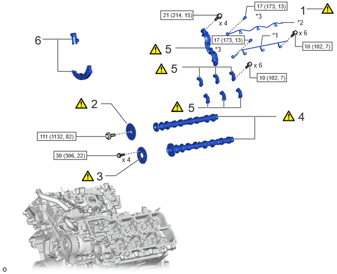
| Procedure | Part Name Code |

|

|

|
|
|---|---|---|---|---|---|
| 1 | SET NO. 1 CYLINDER TO TDC/COMPRESSION | - | ( ) |
- | - |
| 2 | NO. 2 CAMSHAFT TIMING SPROCKET ASSEMBLY | 13529G | () |
- | - |
| 3 | CAMSHAFT TIMING SPROCKET | 13523G | () |
- | - |
| 4 | INTAKE CAMSHAFT SUB-ASSEMBLY LH AND EXHAUST CAMSHAFT SUB-ASSEMBLY LH | - | () |
- | - |
| 5 | NO. 3 CAMSHAFT BEARING CAP AND NO. 4 CAMSHAFT BEARING CAP | - | () |
- | - |
| 6 | CHAIN TENSIONER SLIPPER LH AND NO. 3 CHAIN TENSIONER ASSEMBLY | - | - | - | - |
| *1 | NO. 3 CAMSHAFT OIL FEED PIPE SUB-ASSEMBLY | *2 | NO. 4 CAMSHAFT OIL FEED PIPE SUB-ASSEMBLY |
| *3 | UNION BOLT | - | - |

|
N*m (kgf*cm, ft.*lbf): Specified torque | - | - |
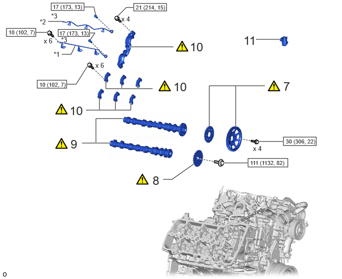
| Procedure | Part Name Code |
|
|
|
|
|---|---|---|---|---|---|
| 7 | CAMSHAFT TIMING SPROCKET AND PUMP DRIVE SHAFT GEAR | - | () |
- | - |
| 8 | NO. 2 CAMSHAFT TIMING SPROCKET ASSEMBLY | 13529G | () |
- | - |
| 9 | INTAKE CAMSHAFT SUB-ASSEMBLY RH AND EXHAUST CAMSHAFT SUB-ASSEMBLY RH | - | () |
- | - |
| 10 | NO. 1 CAMSHAFT BEARING CAP AND NO. 3 CAMSHAFT BEARING CAP | - | () |
- | - |
| 11 | NO. 2 CHAIN TENSIONER ASSEMBLY | 13550 | - | - | - |
| *1 | NO. 1 CAMSHAFT OIL FEED PIPE SUB-ASSEMBLY | *2 | NO. 2 CAMSHAFT OIL FEED PIPE SUB-ASSEMBLY |
| *3 | UNION BOLT | - | - |
|
|
N*m (kgf*cm, ft.*lbf): Specified torque | - | - |
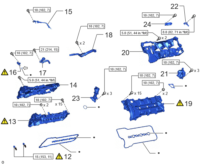
| Procedure | Part Name Code |
|
|
|
|
|---|---|---|---|---|---|
| 12 | STARAIGHT SCREW PLUG | - | () |
- | - |
| 13 | CYLINDER HEAD COVER RH | 11211 | () |
- | - |
| 14 | CYLINDER HEAD COVER SILENCER | 11224 | - | - | - |
| 15 | FUEL PUMP MOTOR WIRE | 23243C | - | - | - |
| 16 | CAMSHAFT POSITION SENSOR | 11101E | () |
- | - |
| 17 | NO. 4 NOZZLE LEAKAGE PIPE | 23764A | - | - | - |
| 18 | NO. 5 WATER BY-PASS PIPE | 16289 | - | - | - |
| 19 | CYLINDER HEAD COVER LH | 11212B | () |
- | - |
| 20 | CYLINDER HEAD COVER LH SILENCER | 11225 | - | - | - |
| 21 | OIL SEPARATOR HOLDER | 12277 | - | - | - |
| 22 | FUEL HOSE BRACKET | 23811C | - | - | - |
| 23 | OIL FILLER CAP HOUSING | 12185 | - | - | - |
| 24 | FUEL PIPE BRACKET | 23211M | - | - | - |
|
|
N*m (kgf*cm, ft.*lbf): Specified torque | ● | Non-reusable part |

|
Toyota Genuine Adhesive 1324, Three Bond 1324 or equivalent |

|
Engine oil |
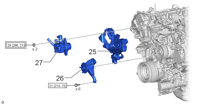
| Procedure | Part Name Code |
|
|
|
|
|---|---|---|---|---|---|
| 25 | TIMING CHAIN COVER INSULATOR | 11336B | - | - | - |
| 26 | FAN BRACKET SUB-ASSEMBLY | 16307A | - | - | - |
| 27 | VANE PUMP ASSEMBLY | 44310 | - | - | - |

|
Tightening torque for "Major areas involving basic vehicle performance such as moving/turning/stopping": N*m (kgf*cm, ft.*lbf) |
|
N*m (kgf*cm, ft.*lbf): Specified torque |
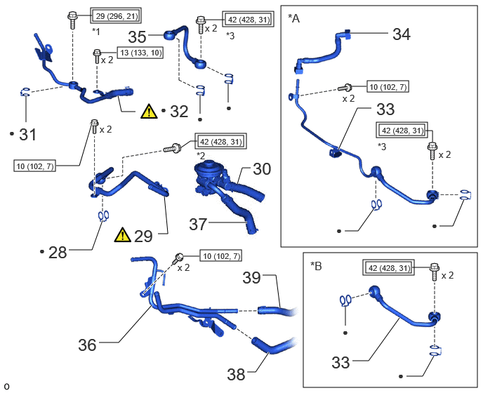
| Procedure | Part Name Code |
|
|
|
|
|---|---|---|---|---|---|
| 28 | GASKET | 23811K | - | - | - |
| 29 | NO. 1 FUEL PIPE | 23811G | () |
- | - |
| 30 | NO. 4 FUEL HOSE | 23282D | - | - | - |
| 31 | GASKET | 23801N | - | - | - |
| 32 | NO. 5 NOZZLE LEAKAGE PIPE | 23765 | () |
- | - |
| 33 | NO. 3 FUEL PIPE | 23815D | - | - | - |
| 34 | FUEL TUBE SUB-ASSEMBLY | 23901H | - | - | - |
| 35 | NO. 4 FUEL PIPE | 23816 | - | - | - |
| 36 | NO. 2 FUEL PIPE | 23812D | - | - | - |
| 37 | NO. 3 FUEL HOSE | 23274D | - | - | - |
| 38 | NO. 1 FUEL HOSE | 23271H | - | - | - |
| 39 | NO. 2 FUEL HOSE | 23273H | - | - | - |
| *A | w/ DPF | *B | w/o DPF |
| *1 | NOZZLE LEAKAGE PIPE SCREW | *2 | INJECTOR FOLLOW SCREW |
| *3 | UNION BOLT | - | - |
|
|
Tightening torque for "Major areas involving basic vehicle performance such as moving/turning/stopping": N*m (kgf*cm, ft.*lbf) |
|
N*m (kgf*cm, ft.*lbf): Specified torque |
| ● | Non-reusable part | - | - |
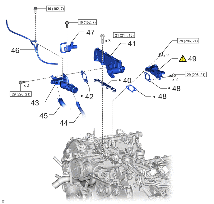
| Procedure | Part Name Code |
|
|
|
|
|---|---|---|---|---|---|
| 40 | TURBO OIL INLET GASKET | 15471 | - | - | - |
| 41 | TURBOCHARGER STAY | 17293 | - | - | - |
| 42 | WATER OUTLET HOUSING GASKET | 16343 | - | - | - |
| 43 | WATER OUTLET | 16331 | - | - | - |
| 44 | NO. 4 OIL COOLER HOSE | 15776A | - | - | - |
| 45 | WATER HOSE | 16571E | - | - | - |
| 46 | NO. 1 VACUUM TRANSMITTING PIPE SUB-ASSEMBLY | 25706 | - | - | - |
| 47 | NO. 1 VACUUM SWITCHING VALVE ASSEMBLY | 25860 | - | - | - |
| 48 | WATER OUTLET GASKET | 16341 | - | - | - |
| 49 | NO. 2 WATER OUTLET PIPE | 16335B | () |
- | - |
|
|
N*m (kgf*cm, ft.*lbf): Specified torque | ● | Non-reusable part |
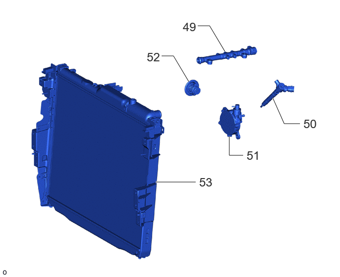
| Procedure | Part Name Code |
|
|
|
|
|---|---|---|---|---|---|
| 50 | COMMON RAIL ASSEMBLY | 23810A | - | - | - |
| 51 | INJECTOR ASSEMBLY | 23670 | - | - | - |
| 52 | VACUUM PUMP ASSEMBLY | 29300 | - | - | - |
| 53 | THERMOSTAT | 16331A | - | - | - |
| 54 | RADIATOR ASSEMBLY | 16400 | - | - | - |
PROCEDURE

 1.SET NO. 1 CYLINDER TO TDC/COMPRESSION
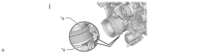
| *a | Timing Mark | - | - |
Turn the crankshaft clockwise to align the timing mark (cutout) with the timing mark of the No. 2 timing chain cover insulator, and set the No. 1 cylinder to TDC/compression.
13529G 2.INSTALL NO. 2 CAMSHAFT TIMING SPROCKET ASSEMBLY (for Bank 2)
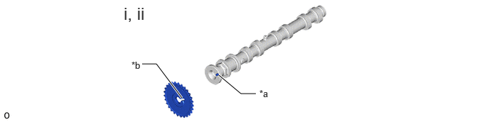
| *a | Knock Pin | *b | Knock Pin Hole |
Align the knock pin of the exhaust camshaft sub-assembly LH with the knock pin hole of the No. 2 camshaft timing sprocket assembly, and install the No. 2 camshaft timing sprocket assembly.
Temporarily install the No. 2 camshaft timing sprocket assembly to the exhaust camshaft sub-assembly LH with the bolt.
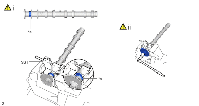
| *a | Hexagonal Portion | - | - |
Using SST, grip the hexagonal portion, and then secure SST and exhaust camshaft sub-assembly LH in a vise as shown in the illustration.
- SST
-
09212-31010
- NOTICE:
-
·
Do not damage the exhaust camshaft sub-assembly LH.
·Never grip areas other than the hexagonal portion, as this may cause damage.
Tighten the bolt.
- Torque:
- 111 N*m (1132 kgf*cm, 82 ft.*lbf)
- NOTICE:
-
Be careful not to damage the exhaust camshaft sub-assembly LH and No. 2 camshaft timing sprocket assembly.
13523G 3.INSTALL CAMSHAFT TIMING SPROCKET (for Bank 2)
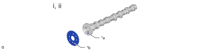
| *a | Knock Pin | *b | Knock Pin Hole |
Align the knock pin of the intake camshaft sub-assembly LH with the knock pin hole of the camshaft timing sprocket, and install the camshaft timing sprocket.
Temporarily install the camshaft timing sprocket to the intake camshaft sub-assembly LH with the 4 bolts.
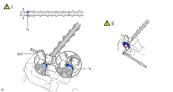
| *a | Hexagonal Portion | - | - |
Using SST, grip the hexagonal portion, and then secure SST and intake camshaft sub-assembly LH in a vise as shown in the illustration.
- SST
-
09212-31010
- NOTICE:
-
·
Do not damage the intake camshaft sub-assembly LH.
·Never grip areas other than the hexagonal portion, as this may cause damage.
Tighten the 4 bolts.
- Torque:
- 30 N*m (306 kgf*cm, 22 ft.*lbf)
- NOTICE:
-
Be careful not to damage the intake camshaft sub-assembly LH and camshaft timing sprocket.
4.INSTALL INTAKE CAMSHAFT SUB-ASSEMBLY LH AND EXHAUST CAMSHAFT SUB-ASSEMBLY LH (for Bank 2)
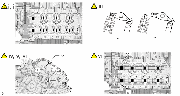
| *a | CORRECT | *b | INCORRECT |
| *c | Paint Mark | *d | Timing Mark |
| *e | Thrust of Camshaft | - | - |

|
Apply Engine Oil | - | - |
Apply a sufficient amount of engine oil to the 12 rollers of the No. 1 valve rocker arm sub-assembly.
Apply a sufficient amount of engine oil to the 8 journals of the cylinder head LH.
Make sure that the No. 1 valve rocker arm sub-assembly is installed as shown in the illustration.
Align the paint mark of the No. 2 chain sub-assembly with the timing mark as shown in the illustration, install the No. 2 chain sub-assembly to the No. 2 camshaft timing sprocket assembly, and set the exhaust camshaft sub-assembly LH.
Align the paint mark of the No. 2 chain sub-assembly with the timing mark as shown in the illustration, install the No. 2 chain sub-assembly to the camshaft timing sprocket, and set the intake camshaft sub-assembly LH.
Check that the timing marks on the camshaft timing sprocket and No. 2 camshaft timing sprocket assembly are aligned with the paint mark on the No. 2 chain sub-assembly.
Apply a sufficient amount of engine oil to the 8 journals and 4 thrust surfaces of the camshaft.
5.INSTALL NO. 3 CAMSHAFT BEARING CAP AND NO. 4 CAMSHAFT BEARING CAP (for Bank 2)
|
|
Click here() |
6.INSTALL CHAIN TENSIONER SLIPPER LH AND NO. 3 CHAIN TENSIONER ASSEMBLY (for Bank 2)
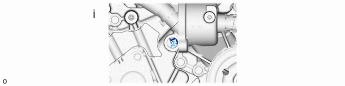
Remove the pin securing the chain tensioner slipper LH and No. 3 chain tensioner assembly.
7.INSTALL CAMSHAFT TIMING SPROCKET AND PUMP DRIVE SHAFT GEAR (for Bank 1)
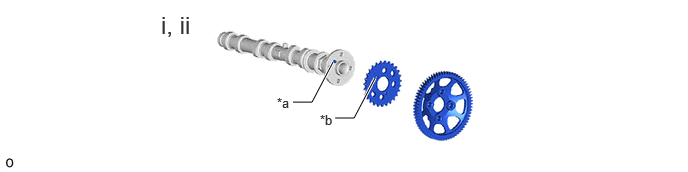
| *a | Knock Pin | *b | Knock Pin Hole |
Align the knock pin of the exhaust camshaft sub-assembly RH with the knock pin hole of the camshaft timing sprocket, and install the camshaft timing sprocket.
Temporarily install the camshaft timing sprocket and pump drive shaft gear to the exhaust camshaft sub-assembly RH with the 4 bolts.
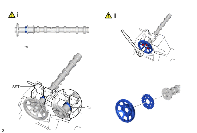
| *a | Hexagonal Portion | - | - |
Using SST, grip the hexagonal portion, and then secure SST and exhaust camshaft sub-assembly RH in a vise as shown in the illustration.
- SST
-
09212-31010
- NOTICE:
-
·
Do not damage the exhaust camshaft sub-assembly RH.
·Never grip areas other than the hexagonal portion, as this may cause damage.
Tighten the 4 bolts.
- Torque:
- 30 N*m (306 kgf*cm, 22 ft.*lbf)
- NOTICE:
-
Be careful not to damage the exhaust camshaft sub-assembly RH, camshaft timing sprocket and punp drive shaft gear.
13529G 8.INSTALL NO. 2 CAMSHAFT TIMING SPROCKET ASSEMBLY (for Bank 1)
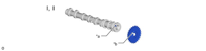
| *a | Knock Pin | *b | Knock Pin Hole |
Align the knock pin of the intake camshaft sub-assembly RH with the knock pin hole of the No. 2 camshaft timing sprocket assembly, and install the No. 2 camshaft timing sprocket assembly.
Temporarily install the No. 2 camshaft timing sprocket assembly to the intake camshaft sub-assembly RH with the bolt.
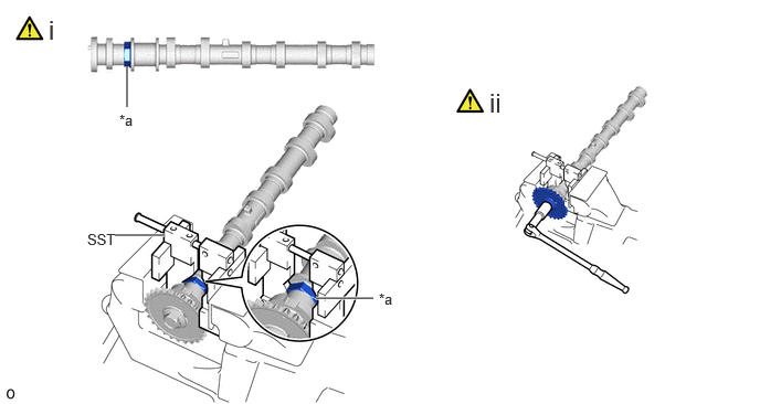
| *a | Hexagonal Portion | - | - |
Using SST, grip the hexagonal portion, and then secure SST and intake camshaft sub-assembly RH in a vise as shown in the illustration.
- SST
-
09212-31010
- NOTICE:
-
·
Do not damage the intake camshaft sub-assembly RH.
·Never grip areas other than the hexagonal portion, as this may cause damage.
Tighten the bolt.
- Torque:
- 111 N*m (1132 kgf*cm, 82 ft.*lbf)
- NOTICE:
-
Be careful not to damage the intake camshaft sub-assembly RH and No. 2 camshaft timing sprocket assembly.
9.INSTALL INTAKE CAMSHAFT SUB-ASSEMBLY RH AND EXHAUST CAMSHAFT SUB-ASSEMBLY RH (for Bank 1)
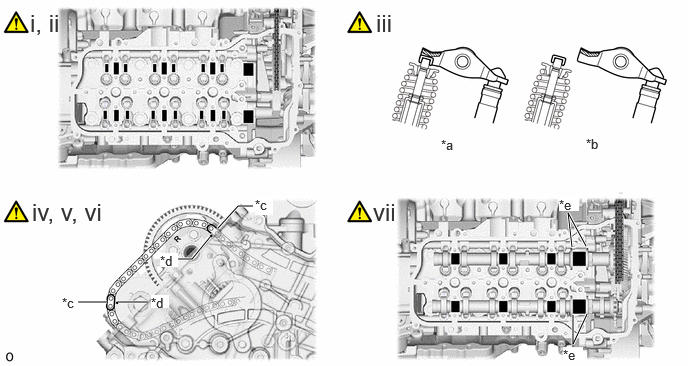
| *a | CORRECT | *b | INCORRECT |
| *c | Paint Mark | *d | Timing Mark |
| *e | Thrust of Camshaft | - | - |
|
|
Apply Engine Oil | - | - |
Apply a sufficient amount of engine oil to the 12 rollers of the No. 1 valve rocker arm sub-assembly.
Apply a sufficient amount of engine oil to the 8 journals of the cylinder head sub-assembly.
Make sure that the No. 1 valve rocker arm sub-assembly is installed as shown in the illustration.
Align the paint mark of the No. 2 chain sub-assembly with the timing mark as shown in the illustration, install the No. 2 chain sub-assembly to the camshaft timing sprocket, and set the exhaust camshaft sub-assembly RH.
Align the paint mark of the No. 2 chain sub-assembly with the timing mark as shown in the illustration, install the No. 2 chain sub-assembly to the No. 2 camshaft timing sprocket assembly, and set the intake camshaft sub-assembly RH.
Check that the timing marks on the camshaft timing sprocket and No. 2 camshaft timing sprocket assembly are aligned with the paint mark on the No. 2 chain sub-assembly.
Apply a sufficient amount of engine oil to the 8 journals and 4 thrust surfaces of the camshaft.
10.INSTALL NO. 1 CAMSHAFT BEARING CAP AND NO. 3 CAMSHAFT BEARING CAP (for Bank 1)
|
|
Click here() |
13550 11.INSTALL NO. 2 CHAIN TENSIONER ASSEMBLY (for Bank 1)
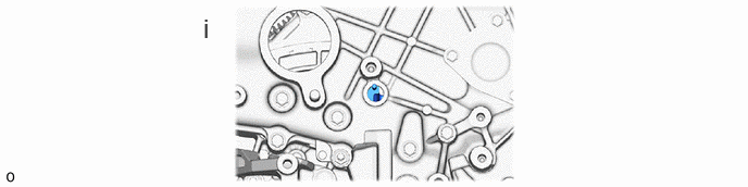
Remove the pin securing the No. 2 chain tensioner assembly.
12.INSTALL STARAIGHT SCREW PLUG
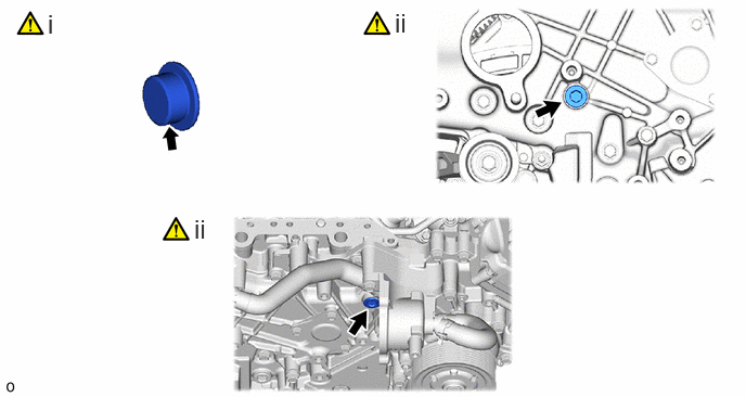
Apply adhesive to the straight screw plugs.
- Adhesive:
-
Toyota Genuine Adhesive 1324, Three Bond 1324 or equivalent.
Using a 10 mm hexagon wrench, install the straight screw plugs.
- Torque:
- 15 N*m (153 kgf*cm, 11 ft.*lbf)
11211 13.INSTALL CYLINDER HEAD COVER RH
|
|
Click here() |
11224 14.INSTALL CYLINDER HEAD COVER SILENCER
23243C 15.CONNECT FUEL PUMP MOTOR WIRE
11101E 16.INSTALL CAMSHAFT POSITION SENSOR
|
|
Click here() |
23764A 17.INSTALL NO. 4 NOZZLE LEAKAGE PIPE
16289 18.INSTALL NO. 5 WATER BY-PASS PIPE
11212B 19.INSTALL CYLINDER HEAD COVER LH
|
|
Click here() |
11225 20.INSTALL CYLINDER HEAD COVER LH SILENCER
12277 21.INSTALL OIL SEPARATOR HOLDER
23881C 22.INSTALL FUEL HOSE BRACKET
- Torque:
- 8.0 N*m (82 kgf*cm, 71 in.*lbf)
12185 23.INSTALL OIL FILLER CAP HOUSING
23211M 24.INSTALL FUEL PIPE BRACKET
11336B 25.INSTALL TIMING CHAIN COVER INSULATOR
16307A 26.INSTALL FAN BRACKET SUB-ASSEMBLY
44310 27.CONNECT VANE PUMP ASSEMBLY
23811K 28.INSTALL GASKET
23811G 29.INSTALL NO. 1 FUEL PIPE
|
|
Click here() |
23282D 30.CONNECT NO. 4 FUEL HOSE
23801N 31.INSTALL GASKET
23765 32.INSTALL NO. 5 NOZZLE LEAKAGE PIPE
|
|
Click here() |
23815D 33.INSTALL NO. 3 FUEL PIPE
23901H 34.INSTALL FUEL TUBE SUB-ASSEMBLY
23816 35.INSTALL NO. 4 FUEL PIPE
23812D 36.INSTALL NO. 2 FUEL PIPE
23274D 37.CONNECT NO. 3 FUEL HOSE
23271H 38.CONNECT NO. 1 FUEL HOSE
23273H 39.CONNECT NO. 2 FUEL HOSE
15471 40.INSTALL TURBO OIL INLET GASKET
17293 41.INSTALL TURBOCHARGER STAY
16343 42.INSTALL WATER OUTLET HOUSING GASKET
16331 43.INSTALL WATER OUTLET
15776A 44.CONNECT NO. 4 OIL COOLER HOSE
16571E 45.CONNECT WATER HOSE
25706 46.INSTALL NO. 1 VACUUM TRANSMITTING PIPE SUB-ASSEMBLY
25860 47.INSTALL NO. 1 VACUUM SWITCHING VALVE ASSEMBLY
16341 48.INSTALL WATER OUTLET GASKET
16335B 49.INSTALL NO. 2 WATER OUTLET PIPE
|
|
Click here() |
23810A 50.INSTALL COMMON RAIL ASSEMBLY
23670 51.INSTALL INJECTOR ASSEMBLY
29300 52.INSTALL VACUUM PUMP ASSEMBLY
16331A 53.INSTALL THERMOSTAT
16400 54.INSTALL RADIATOR ASSEMBLY