F33A-FTV ENGINE MECHANICAL CYLINDER HEAD GASKET INSTALLATION
CAUTION / NOTICE / HINT
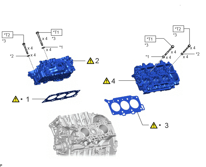
| Procedure | Part Name Code |

|

|

|
|
|---|---|---|---|---|---|
| 1 | CYLINDER HEAD GASKET | 11115 | ( ) |
- | - |
| 2 | CYLINDER HEAD SUB-ASSEMBLY | 11101 | () |
- | - |
| 3 | NO. 2 CYLINDER HEAD GASKET | 11116 | () |
- | - |
| 4 | CYLINDER HEAD LH | 11102 | () |
- | - |
| *1 | CYLINDER HEAD SET PLATE WASHER | *2 | CYLINDER HEAD SET BOLT SPACER |
| *3 | CYLINDER HEAD SET BOLT | - | - |

|
N*m (kgf*cm, ft.*lbf): Specified torque | ● | Non-reusable part |
| *T1 | 1st: 100 (1020, 74) 2nd: Turn 90° 3rd: Turn 90° 4th: Turn 90° |
*T2 | 1st: 50 (510, 37) 2nd: Turn 90° 3rd: Turn 90° 4th: Turn 90° |
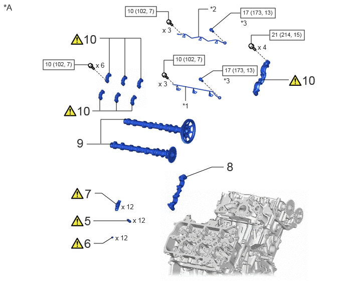
| Procedure | Part Name Code |
|
|
|
|
|---|---|---|---|---|---|
| 5 | VALVE LASH ADJUSTER ASSEMBLY | 13750 | () |
- | - |
| 6 | VALVE STEM CAP | 13716 | () |
- | - |
| 7 | NO. 1 VALVE ROCKER ARM SUB-ASSEMBLY | 13801 | () |
- | - |
| 8 | NO. 2 CAMSHAFT BEARING CAP | - | - | - | - |
| 9 | INTAKE CAMSHAFT SUB-ASSEMBLY RH AND EXHAUST CAMSHAFT SUB-ASSEMBLY RH | - | - | - | - |
| 10 | NO. 1 CAMSHAFT BEARING CAP AND NO. 3 CAMSHAFT BEARING CAP | - | () |
- | - |
| *A | for Bank 1 | - | - |
| *1 | NO. 1 CAMSHAFT OIL FEED PIPE SUB-ASSEMBLY | *2 | NO. 2 CAMSHAFT OIL FEED PIPE SUB-ASSEMBLY |
| *3 | UNION BOLT | - | - |
|
|
N*m (kgf*cm, ft.*lbf): Specified torque | - | - |
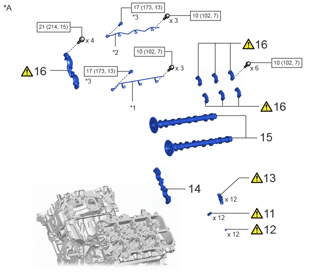
| Procedure | Part Name Code |
|
|
|
|
|---|---|---|---|---|---|
| 11 | VALVE LASH ADJUSTER ASSEMBLY | 13750 | () |
- | - |
| 12 | VALVE STEM CAP | 13716 | () |
- | - |
| 13 | NO. 1 VALVE ROCKER ARM SUB-ASSEMBLY | 13801 | () |
- | - |
| 14 | NO. 5 CAMSHAFT BEARING CAP | - | - | - | - |
| 15 | INTAKE CAMSHAFT SUB-ASSEMBLY LH AND EXHAUST CAMSHAFT SUB-ASSEMBLY LH | - | - | - | - |
| 16 | NO. 3 CAMSHAFT BEARING CAP AND NO. 4 CAMSHAFT BEARING CAP | - | () |
- | - |
| *A | for Bank 2 | - | - |
| *1 | NO. 3 CAMSHAFT OIL FEED PIPE SUB-ASSEMBLY | *2 | NO. 4 CAMSHAFT OIL FEED PIPE SUB-ASSEMBLY |
| *3 | UNION BOLT | - | - |
|
|
N*m (kgf*cm, ft.*lbf): Specified torque | - | - |
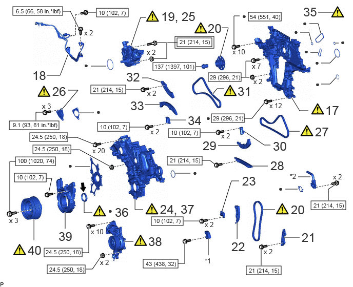
| Procedure | Part Name Code |
|
|
|
|
|---|---|---|---|---|---|
| 17 | TIMING CHAIN COVER ASSEMBLY | 11310 | () |
- | - |
| 18 | FUEL PUMP MOTOR WIRE | 23243C | - | - | - |
| 19 | TEMPORARILY INSTALL INJECTION OR SUPPLY PUMP ASSEMBLY | 22100 | () |
- | - |
| 20 | NO. 1 CHAIN SUB-ASSEMBLY AND SUPPLY PUMP SHAFT SPROCKET | 13506A | () |
- | - |
| 21 | NO. 1 CHAIN VIBRATION DAMPER | 13561 | - | - | - |
| 22 | CHAIN TENSIONER SLIPPER | 13559 | - | - | - |
| 23 | NO. 1 CHAIN TENSIONER ASSEMBLY | 13540 | - | - | - |
| 24 | TEMPORARILY INSTALL TIMING CHAIN OR BELT COVER SUB-ASSEMBLY | 11302 | () |
- | - |
| 25 | INSTALL INJECTION OR SUPPLY PUMP ASSEMBLY | 22100 | () |
- | - |
| 26 | TIMING CHAIN COVER PLATE | 11324 | () |
- | - |
| 27 | NO. 2 CHAIN SUB-ASSEMBLY | 13507 | () |
- | - |
| 28 | NO. 3 CHAIN VIBRATION DAMPER | 13563 | - | - | - |
| 29 | CHAIN TENSIONER SLIPPER LH | 13559F | - | - | - |
| 30 | NO. 3 CHAIN TENSIONER ASSEMBLY | 13560A | - | - | - |
| 31 | NO. 2 CHAIN SUB-ASSEMBLY | 13507 | () |
- | - |
| 32 | NO. 2 CHAIN VIBRATION DAMPER | 13562 | - | - | - |
| 33 | CHAIN TENSIONER SLIPPER RH | 13559E | - | - | - |
| 34 | NO. 2 CHAIN TENSIONER ASSEMBLY | 13550 | - | - | - |
| 35 | NO. 1 CYLINDER TO TDC / COMPRESSION | - | () |
- | - |
| 36 | TIMING CHAIN OR BELT COVER OIL SEAL | 11302A | () |
- | - |
| 37 | TIMING CHAIN OR BELT COVER SUB-ASSEMBLY | 11302 | () |
- | - |
| 38 | ENGINE WATER PUMP ASSEMBLY | 16100 | () |
- | - |
| 39 | NO. 2 TIMING CHAIN COVER INSULATOR | 11339D | - | - | - |
| 40 | CRANKSHAFT PULLEY SUB-ASSEMBLY | 13408 | () |
- | - |
| *1 | NO. 2 BALANCESHAFT | *2 | NO. 4 WATER BY-PASS PIPE |

|
Tightening torque for "Major areas involving basic vehicle performance such as moving/turning/stopping": N*m (kgf*cm, ft.*lbf) |
|
N*m (kgf*cm, ft.*lbf): Specified torque |
| ● | Non-reusable part |

|
MP grease |
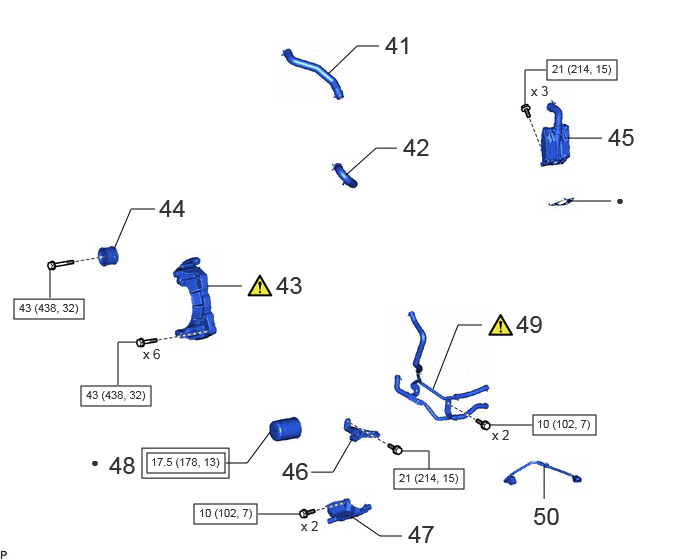
| Procedure | Part Name Code |
|
|
|
|
|---|---|---|---|---|---|
| 41 | NO. 10 WATER BY-PASS HOSE | 16293 | - | - | - |
| 42 | WATER HOSE | 16571E | - | - | - |
| 43 | GENERATOR BRACKET | 12511C | () |
- | - |
| 44 | IDLER PULLEY SUB-ASSEMBLY | 16603B | - | - | - |
| 45 | INTERCOOLER SUPPORT BRACKET | 17940E | - | - | - |
| 46 | NO. 1 COMPRESSOR MOUNTING BRACKET | 88431 | - | - | - |
| 47 | OIL FILTER RECEIVER | 15674 | - | - | - |
| 48 | OIL FILTER SUB-ASSEMBLY | 15601 | - | - | - |
| 49 | NO. 2 WATER BY-PASS PIPE SUB-ASSEMBLY | 16207 | () |
- | - |
| 50 | NO. 1 CONNECTING WIRE | 27148D | - | - | - |
|
|
Tightening torque for "Major areas involving basic vehicle performance such as moving/turning/stopping": N*m (kgf*cm, ft.*lbf) |
|
N*m (kgf*cm, ft.*lbf): Specified torque |
| ● | Non-reusable part | - | - |
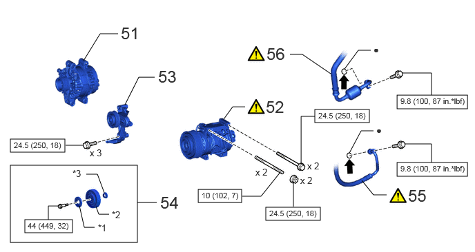
| Procedure | Part Name Code |
|
|
|
|
|---|---|---|---|---|---|
| 51 | GENERATOR ASSEMBLY | 27060 | - | - | - |
| 52 | COMPRESSOR WITH MAGNET CLUTCH | - | () |
- | - |
| 53 | NO. 2 IDLER PULLEY ASSEMBLY | 16630J | - | - | - |
| 54 | NO. 2 IDLER PULLEY SUB-ASSEMBLY | 16604C | - | - | - |
| 55 | NO. 1 COOLER REFRIGERANT DISCHARGE HOSE | 88711 | () |
- | - |
| 56 | SUCTION HOSE SUB-ASSEMBLY | 88704 | () |
- | - |
| *1 | DUST COVER | *2 | IDLE PULLEY SUB-ASSEMBLY |
| *3 | IDLE PULLEY COLLAR | - | - |
|
|
N*m (kgf*cm, ft.*lbf): Specified torque | ● | Non-reusable part |
|
|
Compressor oil ND-OIL 8 or equivalent | - | - |
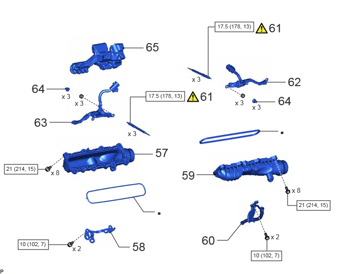
| Procedure | Part Name Code |
|
|
|
|
|---|---|---|---|---|---|
| 57 | INTAKE MANIFOLD | 17111 | - | - | - |
| 58 | NO. 2 WIRE HARNESS CLAMP | - | - | - | - |
| 59 | NO. 2 INTAKE MANIFOLD | 17112 | - | - | - |
| 60 | ENGINE OIL LEVEL DIPSTICK GUIDE | 11452 | - | - | - |
| 61 | GLOW PLUG ASSEMBLY | 19850 | () |
- | - |
| 62 | NO. 1 GLOW PLUG CONNECTOR | 19871 | - | - | - |
| 63 | NO. 2 GLOW PLUG CONNECTOR | 19872 | - | - | - |
| 64 | GLOW PLUG SCREW GROMMET | 19850B | - | - | - |
| 65 | INTAKE MANIFOLD INSULATOR | 17853B | - | - | - |
|
|
N*m (kgf*cm, ft.*lbf): Specified torque | ● | Non-reusable part |
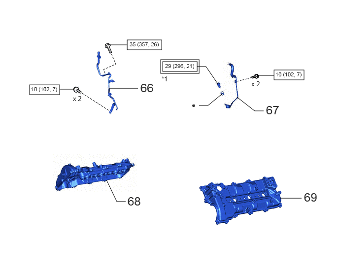
| Procedure | Part Name Code |
|
|
|
|
|---|---|---|---|---|---|
| 66 | STARTER HOSE BRACKET SUB-ASSEMBLY | 28101 | - | - | - |
| 67 | NO. 3 NOZZLE LEAKAGE PIPE | 23763 | - | - | - |
| 68 | CYLINDER HEAD COVER RH | 11211 | - | - | - |
| 69 | CYLINDER HEAD COVER LH | 11212B | - | - | - |
| *1 | UNION BOLT | - | - |
|
|
Tightening torque for "Major areas involving basic vehicle performance such as moving/turning/stopping": N*m (kgf*cm, ft.*lbf) |
|
N*m (kgf*cm, ft.*lbf): Specified torque |
| ● | Non-reusable part | - | - |
PROCEDURE

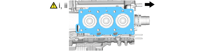
 11115 1.INSTALL CYLINDER HEAD GASKET
|
|
Engine Front | - | - |
Completely remove any carbon or oil, etc. remaining on the bottom surface of the cylinder head sub-assembly and the upper surface of the cylinder block sub-assembly.
- NOTICE:
-
·
Check and clean the cylinder head set bolts and installation holes.
·Do not damage or dent the cylinder head gasket installation surface of the cylinder head sub-assembly and cylinder block sub-assembly.
Install a new cylinder head gasket to the cylinder block sub-assembly as shown in the illustration.
- NOTICE:
-
·
Be careful of the installation direction.
·Gently place the cylinder head sub-assembly in order not to damage the cylinder head gasket with the bottom part of the cylinder head sub-assembly.
11101 2.INSTALL CYLINDER HEAD SUB-ASSEMBLY
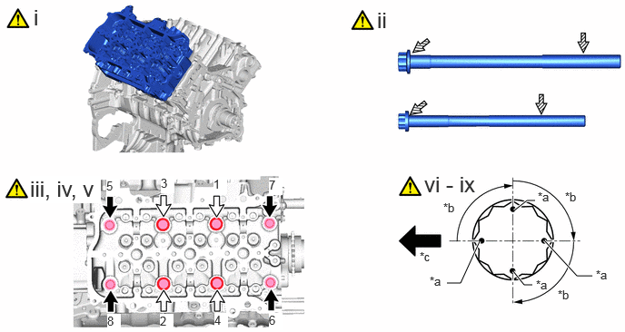
| *a | Paint Mark | *b | 90° |
| *c | Engine Front | - | - |
|
|
Bolt Length 180 mm (7.09 in.) |

|
Bolt Length 215 mm (8.46 in.) |

|
Apply Engine Oil | - | - |
Place the cylinder head sub-assembly on the cylinder block sub-assembly.
- NOTICE:
-
·
Clean and degrease the installation surface.
·Check and clean the cylinder head set bolts and installation holes.
·Tighten the cylinder head set bolts by the plastic region tightening method.
·Be careful not to allow oil to adhere to the bottom part of the cylinder head sub-assembly.
Apply a light coat of engine oil to the threads and seat of the cylinder head set bolt.
Install the 4 cylinder head set plate washers to the 4 cylinder head set bolts.
Install the 4 cylinder head set bolt spacer washers to the 4 cylinder head set bolts.
Temporarily install the 8 cylinder head set bolts, tighten them in several steps in the order shown in the illustration, and then retighten to the specified torque.
- Torque:
- for bolt A : 50 N*m (510 kgf*cm, 37 ft.*lbf)
- for bolt B : 100 N*m (1020 kgf*cm, 74 ft.*lbf)
- NOTICE:
-
·
Install the cylinder head set bolts to their original positions.
·When reusing the cylinder head set bolts, measure their thread diameters. If the result is the minimum or less, replace the cylinder head set bolts with new ones.
Mark the front side of each cylinder head set bolt head with paint.
Retighten the cylinder head set bolts 90° in the tightening order, using the paint marks as the indicator. Further tighten the bolts 90° in the tightening order.
Tighten the cylinder head set bolts an additional 90°.
Check that the paint marks are now at a 270° angle to the front.
- HINT:
-
The paint marks applied to all bolts must be on the left side.
11116 3.INSTALL NO. 2 CYLINDER HEAD GASKET

|
|
Engine Front | - | - |
Completely remove any carbon or oil, etc. remaining on the bottom surface of the cylinder head LH and the upper surface of the cylinder block sub-assembly.
- NOTICE:
-
·
Check and clean the cylinder head set bolts and installation holes.
·Do not damage or dent the No. 2 cylinder head gasket installation surface of the cylinder head LH and cylinder block sub-assembly.
Install a new No. 2 cylinder head gasket to the cylinder block sub-assembly as shown in the illustration.
- NOTICE:
-
·
Be careful of the installation direction.
·Gently place the cylinder head LH in order not to damage the No. 2 cylinder head gasket with the bottom part of the cylinder head LH.
11102 4.INSTALL CYLINDER HEAD LH
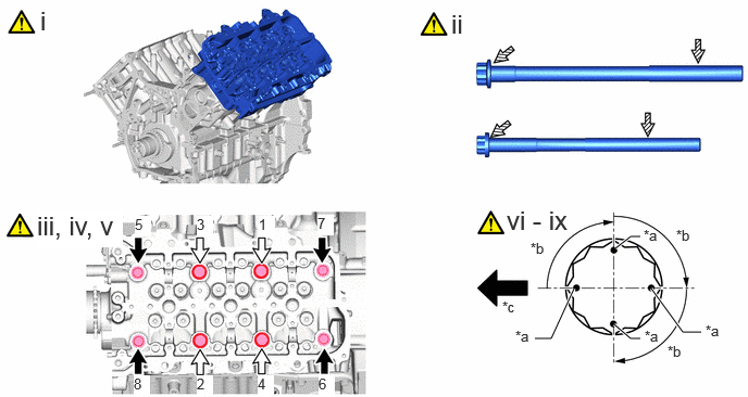
| *a | Paint Mark | *b | 90° |
| *c | Engine Front | - | - |
|
|
Bolt Length 180 mm (7.09 in.) |
|
Bolt Length 215 mm (8.46 in.) |
|
|
Apply Engine Oil | - | - |
Place the cylinder head LH on the cylinder block sub-assembly.
- NOTICE:
-
·
Clean and degrease the installation surface.
·Check and clean the cylinder head set bolts and installation holes.
·Tighten the cylinder head set bolts by the plastic region tightening method.
·Be careful not to allow oil to adhere to the bottom part of the cylinder head LH.
Apply a light coat of engine oil to the threads and seat of the cylinder head set bolt.
Install the 4 cylinder head set plate washers to the 4 cylinder head set bolts.
Install the 4 cylinder head set bolt spacer washers to the 4 cylinder head set bolts.
emporarily install the 8 cylinder head set bolts, tighten them in several steps in the order shown in the illustration, and then retighten to the specified torque.
- Torque:
- for bolt A : 50 N*m (510 kgf*cm, 37 ft.*lbf)
- for bolt B : 100 N*m (1020 kgf*cm, 74 ft.*lbf)
- NOTICE:
-
·
Install the cylinder head set bolts to their original positions.
·When reusing the cylinder head set bolts, measure their thread diameters. If the result is the minimum or less, replace the cylinder head set bolts with new ones.
Mark the front side of each cylinder head set bolt head with paint.
Retighten the cylinder head set bolts 90° in the tightening order, using the paint marks as the indicator. Further tighten the bolts 90° in the tightening order.
Tighten the cylinder head set bolts an additional 90°.
Check that the paint marks are now at a 270° angle to the front.
- HINT:
-
The paint marks applied to all bolts must be on the left side.
13750 5.INSTALL VALVE LASH ADJUSTER ASSEMBLY (for Bank 1)
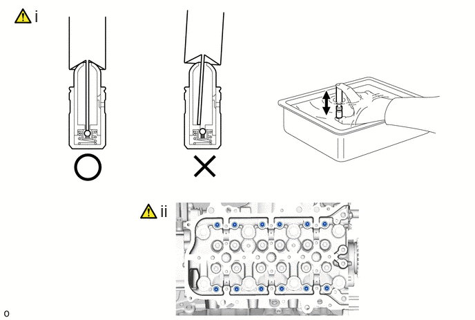
Inspect the valve lash adjuster assembly.
Click hereEngine / Hybrid System>F33A-FTV (ENGINE MECHANICAL)>ENGINE UNIT>INSPECTION
Apply engine oil to the body outside edge and plunger end, and install the 12 valve lash adjuster assemblies vertically in the cylinder head sub-assembly holes.
13716 6.INSTALL VALVE STEM CAP (for Bank 1)
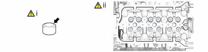
Apply a light coat of engine oil to the valve stem caps.
Install the 12 valve stem caps.
- NOTICE:
-
Install the valve stem cap to the same place it was removed from.
13801 7.INSTALL NO. 1 VALVE ROCKER ARM SUB-ASSEMBLY (for Bank 1)
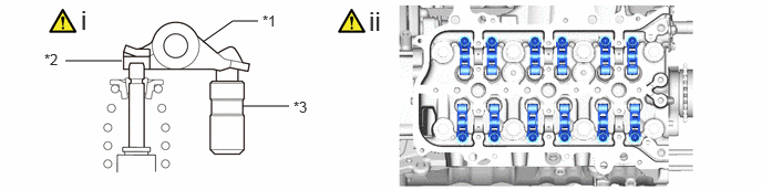
| *1 | No. 1 Valve Rocker Arm Sub-assembly | *2 | Valve Stem Cap |
| *3 | Valve Lash Adjuster Assembly | - | - |
Apply engine oil to the roller portion of the No. 1 valve rocker arm sub-assembly, valve lash adjuster assembly tip and top of the valve stem cap.
Install the 12 No. 1 valve rocker arm sub-assemblies as shown in the illustration.
- NOTICE:
-
Check that the No. 1 valve rocker arm sub-assembly is correctly set to the valve lash adjuster assembly and valve stem cap.
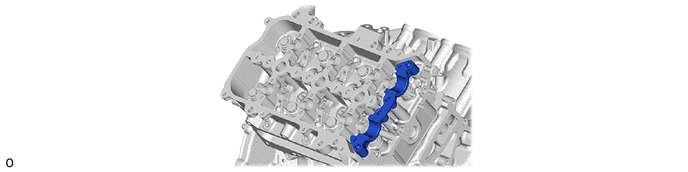
8.INSTALL NO. 2 CAMSHAFT BEARING CAP (for Bank 1)
9.INSTALL INTAKE CAMSHAFT SUB-ASSEMBLY RH AND EXHAUST CAMSHAFT SUB-ASSEMBLY RH (for Bank 1)
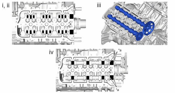
| *a | Thrust of Camshaft | - | - |

|
Apply Engine Oil | - | - |
Apply a sufficient amount of engine oil to the 12 rollers of the No. 1 valve rocker arm sub-assembly.
Apply a sufficient amount of engine oil to the 8 journals of the cylinder head sub-assembly.
Set the intake camshaft sub-assembly RH and exhaust camshaft sub-assembly RH to the cylinder head sub-assembly.
Apply a sufficient amount of engine oil to the 8 journals and 4 thrust surfaces of the camshaft.
10.INSTALL NO. 1 CAMSHAFT BEARING CAP AND NO. 3 CAMSHAFT BEARING CAP (for Bank 1)
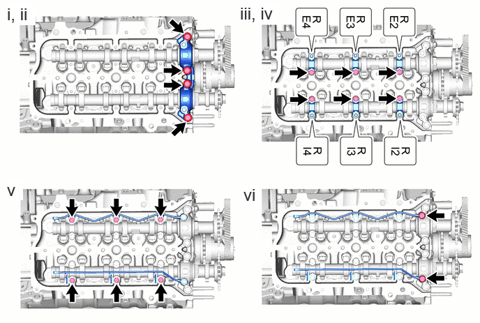
Align the 2 ring pins of the No. 2 camshaft bearing cap with the 2 ring pin holes of the No. 1 camshaft bearing cap, and install the No. 1 camshaft bearing cap.
Temporarily install the 4 bolts.
Check the front marks and numbers of the No. 3 camshaft bearing caps, and temporarily place the caps.
With the oil feed pipe not installed, temporarily install the 6 bolts.
Temporarily install the No. 1 camshaft oil feed pipe sub-assembly and No. 2 camshaft oil feed pipe sub-assembly with the 6 bolts.
- NOTICE:
-
·
When installing the No. 1 camshaft oil feed pipe sub-assembly and No. 2 camshaft oil feed pipe sub-assembly, repair any bending prior to installation. If repair is required, replace it with a new one.
·If the No. 1 camshaft oil feed pipe sub-assembly and No. 2 camshaft oil feed pipe sub-assembly stoppers are deformed, replace them with new ones.
Temporarily install the 2 union bolts.
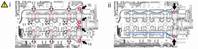
|
|
Camshaft Bearing Cap Bolt A |
|
Camshaft Bearing Cap Bolt B |
Uniformly tighten the 16 bolts in the sequence shown in the illustration.
- Torque:
- Camshaft bearing cap bolt A : 21 N*m (214 kgf*cm, 15 ft.*lbf)
- Camshaft bearing cap bolt B : 10 N*m (102 kgf*cm, 7 ft.*lbf)
Tighten the 2 union bols.
- Torque:
- 17 N*m (173 kgf*cm, 13 ft.*lbf)
13750 11.INSTALL VALVE LASH ADJUSTER ASSEMBLY (for Bank 2)
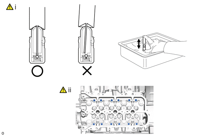
Inspect the valve lash adjuster assembly.
Click hereEngine / Hybrid System>F33A-FTV (ENGINE MECHANICAL)>ENGINE UNIT>INSPECTION
Apply engine oil to the body outside edge and plunger end, and install the 12 valve lash adjuster assemblies vertically in the cylinder head LH holes.
13716 12.INSTALL VALVE STEM CAP (for Bank 2)
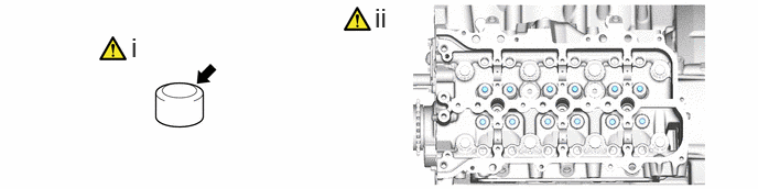
Apply a light coat of engine oil to the valve stem caps.
Install the 12 valve stem caps.
- NOTICE:
-
Install the valve stem cap to the same place it was removed from.
13801 13.INSTALL NO. 1 VALVE ROCKER ARM SUB-ASSEMBLY (for Bank 2)
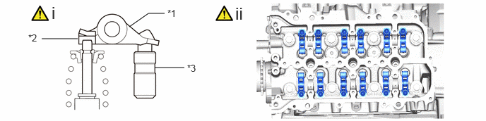
| *1 | No. 1 Valve Rocker Arm Sub-assembly | *2 | Valve Stem Cap |
| *3 | Valve Lash Adjuster Assembly | - | - |
Apply engine oil to the roller portion of the No. 1 valve rocker arm sub-assembly, valve lash adjuster assembly tip and top of the valve stem cap.
Install the 12 No. 1 valve rocker arm sub-assemblies as shown in the illustration.
- NOTICE:
-
Check that the No. 1 valve rocker arm sub-assembly is correctly set to the valve lash adjuster assembly and valve stem cap.
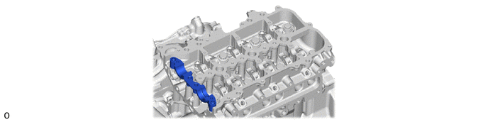
14.INSTALL NO. 5 CAMSHAFT BEARING CAP (for Bank 2)
15.INSTALL INTAKE CAMSHAFT SUB-ASSEMBLY LH AND EXHAUST CAMSHAFT SUB-ASSEMBLY LH (for Bank 2)
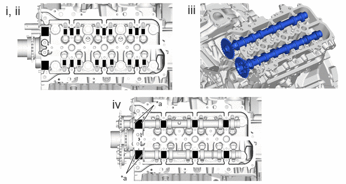
| *a | Thrust of Camshaft | - | - |
|
|
Apply Engine Oil | - | - |
Apply a sufficient amount of engine oil to the 12 rollers of the No. 1 valve rocker arm sub-assembly.
Apply a sufficient amount of engine oil to the 8 journals of the cylinder head LH.
Set the intake camshaft sub-assembly LH and exhaust camshaft sub-assembly LH to the cylinder head LH.
Apply a sufficient amount of engine oil to the 8 journals and 4 thrust surfaces of the camshaft.
16.INSTALL NO. 3 CAMSHAFT BEARING CAP AND NO. 4 CAMSHAFT BEARING CAP (for Bank 2)
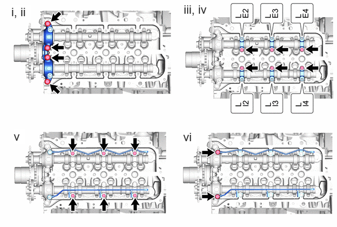
Align the 2 ring pins of the No. 5 camshaft bearing cap with the 2 ring pin holes of the No. 4 camshaft bearing cap, and install the No. 4 camshaft bearing cap.
Temporarily install the 4 bolts.
Check the front marks and numbers of the No. 3 camshaft bearing caps, and temporarily place the caps.
With the oil feed pipe not installed, temporarily install the 6 bolts.
Temporarily install the No. 3 camshaft oil feed pipe sub-assembly and No. 4 camshaft oil feed pipe sub-assembly with the 6 bolts.
- NOTICE:
-
·
When installing the No. 3 camshaft oil feed pipe sub-assembly and No. 4 camshaft oil feed pipe sub-assembly, repair any bending prior to installation. If repair is required, replace it with a new one.
·If the No. 3 camshaft oil feed pipe sub-assembly and No. 4 camshaft oil feed pipe sub-assembly stoppers are deformed, replace them with new ones.
Temporarily install the 2 union bolts.
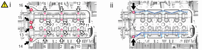
|
|
Camshaft Bearing Cap Bolt A |
|
Camshaft Bearing Cap Bolt B |
Uniformly install the 16 bolts in the sequence shown in the illustration.
- Torque:
- Camshaft bearing cap bolt A : 21 N*m (214 kgf*cm, 15 ft.*lbf)
- Camshaft bearing cap bolt B : 10 N*m (102 kgf*cm, 7 ft.*lbf)
Tighten the 2 union bols.
- Torque:
- : 17 N*m (173 kgf*cm, 13 ft.*lbf)
11310 17.INSTALL TIMING CHAIN COVER ASSEMBLY
|
|
Click here() |
23243C 18.INSTALL FUEL PUMP MOTOR WIRE
22100 19.TEMPORARILY INSTALL INJECTION OR SUPPLY PUMP ASSEMBLY
|
|
Click here() |
13506A 20.INSTALL NO. 1 CHAIN SUB-ASSEMBLY AND SUPPLY PUMP SHAFT SPROCKET
|
|
Click here() |
13561 21.INSTALL NO. 1 CHAIN VIBRATION DAMPER
13559 22.INSTALL CHAIN TENSIONER SLIPPER
13540 23.INSTALL NO. 1 CHAIN TENSIONER ASSEMBLY
11302 24.TEMPORARILY INSTALL TIMING CHAIN OR BELT COVER SUB-ASSEMBLY
|
|
Click here() |
22100 25.INSTALL INJECTION OR SUPPLY PUMP ASSEMBLY
|
|
Click here() |
11324 26.INSTALL TIMING CHAIN COVER PLATE
|
|
Click here() |
13507 27.INSTALL NO. 2 CHAIN SUB-ASSEMBLY
|
|
Click here() |
13563 28.INSTALL NO. 3 CHAIN VIBRATION DAMPER
13559F 29.INSTALL CHAIN TENSIONER SLIPPER LH
13560A 30.INSTALL NO. 3 CHAIN TENSIONER ASSEMBLY
13507 31.INSTALL NO. 2 CHAIN SUB-ASSEMBLY
|
|
Click here() |
13562 32.INSTALL NO. 2 CHAIN VIBRATION DAMPER
13559E 33.INSTALL CHAIN TENSIONER SLIPPER RH
13550 34.INSTALL NO. 2 CHAIN TENSIONER ASSEMBLY
35. NO. 1 CYLINDER TO TDC / COMPRESSION
|
|
Click here() |
11302A 36.INSTALL TIMING CHAIN OR BELT COVER OIL SEAL
|
|
Click here() |
11302 37.INSTALL TIMING CHAIN OR BELT COVER SUB-ASSEMBLY
|
|
Click here() |
16100 38.INSTALL ENGINE WATER PUMP ASSEMBLY
|
|
Click here() |
11339D 39.INSTALL NO. 2 TIMING CHAIN COVER INSULATOR
13408 40.INSTALL CRANKSHAFT PULLEY SUB-ASSEMBLY
|
|
Click here() |
16293 41.INSTALL NO. 10 WATER BY-PASS HOSE
16571E 42.INSTALL WATER HOSE
12511C 43.INSTALL GENERATOR BRACKET
|
|
Click here() |
16603B 44.INSTALL IDLER PULLEY SUB-ASSEMBLY
17940E 45.INSTALL INTERCOOLER SUPPORT BRACKET
88431 46.INSTALL NO. 1 COMPRESSOR MOUNTING BRACKET
15674 47.INSTALL OIL FILTER RECEIVER
15601 48.INSTALL OIL FILTER SUB-ASSEMBLY
16207 49.INSTALL NO. 2 WATER BY-PASS PIPE SUB-ASSEMBLY
|
|
Click here() |
27148D 50.INSTALL NO. 1 CONNECTING WIRE
27060 51.INSTALL GENERATOR ASSEMBLY
for DENSO Made
Click herePower Source / Network>F33A-FTV (BATTERY / CHARGING)>GENERATOR (for DENSO Made)>INSTALLATION
for VALEO Made
Click herePower Source / Network>F33A-FTV (BATTERY / CHARGING)>GENERATOR (for VALEO Made)>INSTALLATION
52.INSTALL COMPRESSOR WITH MAGNET CLUTCH
|
|
Click here() |
16630J 53.INSTALL NO. 2 IDLER PULLEY ASSEMBLY
16604C 54.INSTALL NO. 2 IDLER PULLEY SUB-ASSEMBLY
88711 55.INSTALL NO. 1 COOLER REFRIGERANT DISCHARGE HOSE
|
|
Click here() |
88704 56.CONNECT SUCTION HOSE SUB-ASSEMBLY
|
|
Click here() |
17111 57.INSTALL INTAKE MANIFOLD
58.INSTALL NO. 2 WIRE HARNESS CLAMP
17112 59.INSTALL NO. 2 INTAKE MANIFOLD
11452 60.INSTALL ENGINE OIL LEVEL DIPSTICK GUIDE
19850 61.INSTALL GLOW PLUG ASSEMBLY
|
|
Click here() |
19871 62.INSTALL NO. 1 GLOW PLUG CONNECTOR
19872 63.INSTALL NO. 2 GLOW PLUG CONNECTOR
19850B 64.INSTALL GLOW PLUG SCREW GROMMET
17853B 65.INSTALL INTAKE MANIFOLD INSULATOR
28101 66.INSTALL STARTER HOSE BRACKET SUB-ASSEMBLY
23763 67.INSTALL NO. 3 NOZZLE LEAKAGE PIPE
11211 68.INSTALL CYLINDER HEAD COVER RH
11212B 69.INSTALL CYLINDER HEAD COVER LH