INTAKE / EXHAUST AIR COMPRESSOR INSTALLATION
CAUTION / NOTICE / HINT
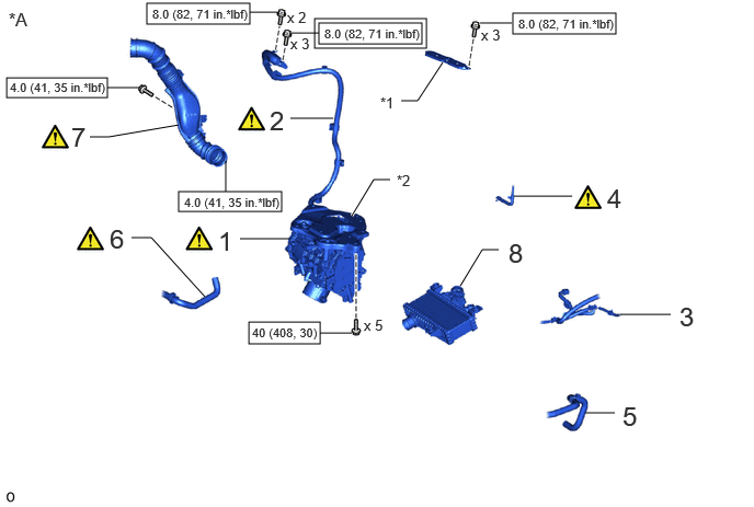
| Procedure | Part Name Code | 
|

|

|
|
|---|---|---|---|---|---|
| 1 | FC AIR COMPRESSOR WITH MOTOR ASSEMBLY | 17A10 | ( ) |
- | - |
| 2 | FC AIR COMPRESSOR MOTOR CABLE ASSEMBLY | 17A90 | ()
|
- | - |
| 3 | WIRE HARNESS | - | - | - | - |
| 4 | NO. 1 AIR COMPRESSOR BREATHER HOSE | 17A40 | ()
|
- | - |
| 5 | NO. 13 FC INVERTER COOLING HOSE | G91CD | - | - | - |
| 6 | NO. 15 FC INVERTER COOLING HOSE | G91CF | ()
|
- | - |
| 7 | AIR CLEANER HOSE ASSEMBLY | 17880D | ()
|
- | - |
| 8 | INTERCOOLER WITH SENSOR ASSEMBLY | 17900 | - | - | - |
| *A | for LHD | - | - |
| *1 | INVERTER TERMINAL COVER | *2 | FC AIR COMPRESSOR BRACKET |

|
Tightening torque for "Major areas involving basic vehicle performance such as moving/turning/stopping": N*m (kgf*cm, ft.*lbf) | 
|
N*m (kgf*cm, ft.*lbf): Specified torque |
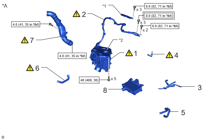
| Procedure | Part Name Code |
|
|
|
|
|---|---|---|---|---|---|
| 1 | FC AIR COMPRESSOR WITH MOTOR ASSEMBLY | 17A10 | ()
|
- | - |
| 2 | FC AIR COMPRESSOR MOTOR CABLE ASSEMBLY | 17A90 | ()
|
- | - |
| 3 | WIRE HARNESS | - | - | - | - |
| 4 | NO. 1 AIR COMPRESSOR BREATHER HOSE | 17A40 | ()
|
- | - |
| 5 | NO. 13 FC INVERTER COOLING HOSE | G91CD | - | - | - |
| 6 | NO. 15 FC INVERTER COOLING HOSE | G91CF | ()
|
- | - |
| 7 | AIR CLEANER HOSE ASSEMBLY | 17880D | ()
|
- | - |
| 8 | INTERCOOLER WITH SENSOR ASSEMBLY | 17900 | - | - | - |
| *A | for RHD | - | - |
| *1 | INVERTER TERMINAL COVER | *2 | FC AIR COMPRESSOR BRACKET |
|
|
Tightening torque for "Major areas involving basic vehicle performance such as moving/turning/stopping": N*m (kgf*cm, ft.*lbf) |
|
N*m (kgf*cm, ft.*lbf): Specified torque |
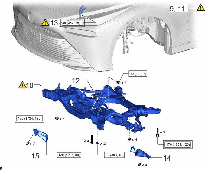
| Procedure | Part Name Code |
|
|
|
|
|---|---|---|---|---|---|
| 9 | HOLDING BAR | - | - | - | - |
| 10 | FRONT FRAME ASSEMBLY | 51100G | ()
|
- | - |
| 11 | ENGINE SUPPORT BRIDGE | - | - | - | - |
| 12 | WIRE HARNESS CLAMP BRACKET | - | - | - | - |
| 13 | NO. 2 STEERING INTERMEDIATE SHAFT ASSEMBLY | 45260 | ()
|
- | - |
| 14 | FRONT COMPARTMENT SIDE COVER LH | 51474C | - | - | - |
| 15 | FRONT COMPARTMENT SIDE COVER RH | 51473D | - | - | - |
|
|
Tightening torque for "Major areas involving basic vehicle performance such as moving/turning/stopping": N*m (kgf*cm, ft.*lbf) |
|
N*m (kgf*cm, ft.*lbf): Specified torque |
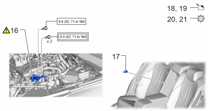
| Procedure | Part Name Code |
|
|
|
|
|---|---|---|---|---|---|
| 16 | FC CONVERTER POWER OUTLET CABLE (INVERTER WITH CONVERTER ASSEMBLY) | G9200A | ()
|
- | - |
| 17 | SERVICE PLUG GRIP | G3834 | - | - | - |
| 18 | ADD COOLANT (for Inverter) | - | - | ()
|
- |
| 19 | ADD COOLANT (TOYOTA GENUINE FC STACK COOLANT (Pre-mixed)) | - | - | ()
|
- |
| 20 | INSPECT FOR COOLANT LEAK (for Inverter) | - | - | - | ()
|
| 21 | INSPECT FOR COOLANT (TOYOTA GENUINE FC STACK COOLANT (Pre-mixed)) LEAK | - | - | - | ()
|
|
|
Tightening torque for "Major areas involving basic vehicle performance such as moving/turning/stopping": N*m (kgf*cm, ft.*lbf) |
|
N*m (kgf*cm, ft.*lbf): Specified torque |
| Procedure | Part Name Code |
|
|
|
|
|---|---|---|---|---|---|
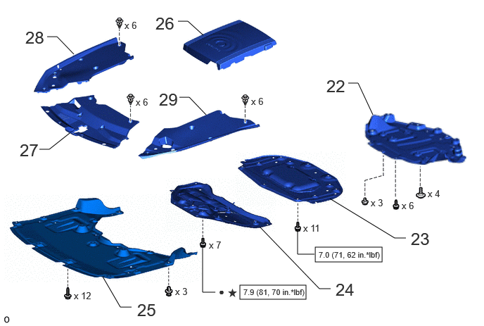
| 22 | REAR NO. 4 FLOOR BOARD SUB-ASSEMBLY | 58404B | - | - | - |
| 23 | FRONT COMPARTMENT UNDER COVER ASSEMBLY | 51420A | - | - | - |
| 24 | FRONT LOWER SUSPENSION MEMBER PROTECTOR | 51219 | - | - | - |
| 25 | FRONT COMPARTMENT UNDER COVER | 51441N | - | - | - |
| 26 | FC STACK COVER SUB-ASSEMBLY | 1A906 | - | - | - |
| 27 | RADIATOR LOWER AIR DEFLECTOR | 53295 | - | - | - |
| 28 | RADIATOR COVER PLATE | 53291B | - | - | - |
| 29 | UPPER RADIATOR SUPPORT SEAL | 53292A | - | - | - |
|
|
N*m (kgf*cm, ft.*lbf): Specified torque | ● | Non-reusable part |
| ★ | Precoated part | - | - |
PROCEDURE

 17A10
1.INSTALL FC AIR COMPRESSOR WITH MOTOR ASSEMBLY
|
|
|
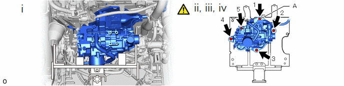
Support the FC air compressor with motor assembly with a transmission jack.
Temporarily install the FC air compressor with motor assembly and FC air compressor bracket to the intercooler bracket with the bolt A.
Temporarily install the FC air compressor with motor assembly and FC air compressor bracket to the stack frame with the other 4 bolts.
Fully tighten the 5 bolts in the order shown in the illustration.
- Torque:
- 40 N*m (408 kgf*cm, 30 ft.*lbf)
17A90
2.CONNECT FC AIR COMPRESSOR MOTOR CABLE ASSEMBLY
|
|
|
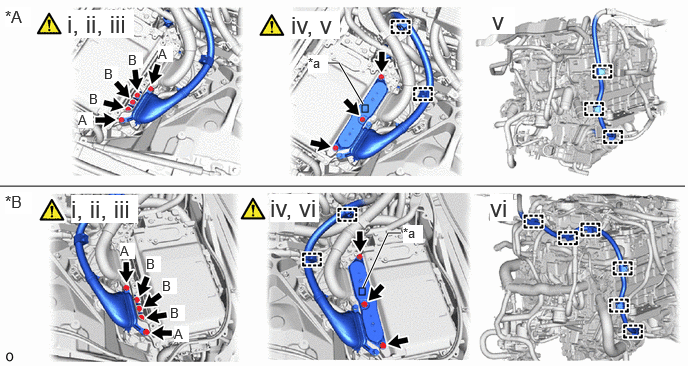
| *A | for LHD | *B | for RHD |
| *a | Interlock Connector | - | - |
Temporarily install the FC air compressor motor cable assembly to the inverter with converter assembly with the 5 bolts.
- NOTICE:
- ·
To prevent damage to the threaded portion, be sure to perform the work by hand.
·Do not touch the rubber seal or terminal portion of the connector.
·When connecting, do not damage or scratch the terminal portions, connector housing, or inverter with converter assembly.
Using an insulated tool, tighten the 2 bolts A.
- Torque:
- 8.0 N*m (82 kgf*cm, 71 in.*lbf)
Using an insulated tool, tighten the 3 bolts B.
- Torque:
- 8.0 N*m (82 kgf*cm, 71 in.*lbf)
Install the inverter terminal cover to the inverter with converter assembly with the 3 bolts.
- Torque:
- 8.0 N*m (82 kgf*cm, 71 in.*lbf)
- NOTICE:
- ·
Make sure that the rubber seal of the inverter terminal cover is securely installed and that no foreign matter is adhering to it, then install it.
·Do not touch the rubber seal of the inverter terminal cover.
·Securely connect the interlock connector.
for LHD:
Connect the 5 clamps.
for RHD:
Connect the 8 clamps.
3.CONNECT WIRE HARNESS
17A40
4.CONNECT NO. 1 AIR COMPRESSOR BREATHER HOSE
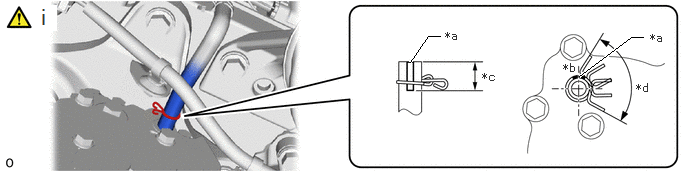
| *a | Hose Paint Mark | *b | Upper Side of Vehicle |
| *c | Make sure to position the hose clip above the hose paint mark | *d | Make sure the hose clip does not interfere with the bolt of the FC air compressor with motor assembly |
Connect the No. 1 air compressor breather hose to the FC air compressor with motor assembly and slide the hose clip to secure it.
- NOTICE:
-
Make sure to position the hose clip as shown in the illustration.
G91CD
5.CONNECT NO. 13 FC INVERTER COOLING HOSE
G91CF
6.CONNECT NO. 15 FC INVERTER COOLING HOSE
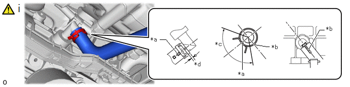
| *a | Hose Paint Mark (Yellow) | *b | Hose Paint Mark (White) |
| *c | 120° | *d | 2 to 7 mm (0.0787 to 0.276 in.) |
Connect the No. 15 FC inverter cooling hose to the FC air compressor with motor assembly and slide the hose clip to secure it.
- NOTICE:
-
Make sure to position the hose clip as shown in the illustration.
17880D
7.INSTALL AIR CLEANER HOSE ASSEMBLY
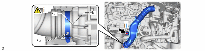
| *a | Protrusion of Hose | *b | Groove of FC Air Compressor With Motor Assembly |
| *c | Protrusion of Hose (for hose clamp positioning) | - | - |
Connect the air cleaner hose assembly to the FC air compressor with motor assembly with hose clamp as shown in the illustration.
- Torque:
- 4.0 N*m (41 kgf*cm, 35 in.*lbf)
- NOTICE:
-
Insert the protrusion of hose (for hose clamp positioning) into the hole of hose clamp and install.
Install the air cleaner hose assembly with the bolt.
- Torque:
- 4.0 N*m (41 kgf*cm, 35 in.*lbf)
17900
8.INSTALL INTERCOOLER ASSEMBLY WITH SENSOR
9.REMOVE HOLDING BAR
51100G
10.INSTALL FRONT FRAME ASSEMBLY
|
|
Click here()
|
11.REMOVE ENGINE SUPPORT BRIDGE
12.CONNECT WIRE HARNESS CLAMP BRACKET
45260
13.CONNECT NO. 2 STEERING INTERMEDIATE SHAFT ASSEMBLY
|
|
Click here()
|
51474C
14.INSTALL FRONT COMPARTMENT SIDE COVER LH
51473D
15.INSTALL FRONT COMPARTMENT SIDE COVER RH
Use the same procedure as for the LH side.
G9200A
16.CONNECT FC CONVERTER POWER OUTLET CABLE (INVERTER WITH CONVERTER ASSEMBLY)
|
|
Click here()
|
G3834
17.INSTALL SERVICE PLUG GRIP
18.ADD COOLANT (for Inverter)
19.ADD COOLANT (TOYOTA GENUINE FC STACK COOLANT (Pre-mixed))
20.INSPECT FOR COOLANT LEAK (for Inverter)
21.INSPECT FOR COOLANT (TOYOTA GENUINE FC STACK COOLANT (Pre-mixed)) LEAK
58404B
22.INSTALL REAR NO. 4 FLOOR BOARD SUB-ASSEMBLY
51420A
23.INSTALL FRONT COMPARTMENT UNDER COVER ASSEMBLY
51219
24.INSTALL FRONT LOWER SUSPENSION MEMBER PROTECTOR
51441N
25.INSTALL FRONT COMPARTMENT UNDER COVER
1A906
26.INSTALL FC STACK COVER SUB-ASSEMBLY
53295
27.INSTALL LOWER RADIATOR AIR DEFLECTOR
53291B
28.INSTALL RADIATOR COVER PLATE
53292A
29.INSTALL UPPER RADIATOR SUPPORT SEAL