DOOR / HATCH FRONT DOOR ADJUSTMENT
CAUTION / NOTICE / HINT
The necessary procedures (adjustment, calibration, initialization, or registration) that must be performed after parts are removed and installed, or replaced during front door disassembly/reassembly are shown below.
| Replaced Part or Performed Procedure | Necessary Procedure | Effect/Inoperative Function when Necessary Procedure not Performed | Link |
|---|---|---|---|
|
*: When performing learning using the GTS. Click here( |
|||
| Removal and installation of auxiliary battery terminal | Perform steering sensor zero point calibration | Lane control system | ( ) |
| Parking support brake system (for HV model)* | |||
| Pre-collision system | |||
| Memorize steering angle neutral point | Parking assist monitor system | ()
|
|
| Panoramic view monitor system (for HV model) | ()
|
||
| Reset back door close position | Power back door system (for HV model) | ()
|
|
| Power back door initialization | Power door lock control system | ()
|
|
- NOTICE:
-
After the ignition switch is turned off, the navigation system requires approximately a minute to record various types of memory and settings. As a result, after turning the ignition switch off, wait a minute or more before disconnecting the cable from the negative (-) auxiliary battery terminal.
| Replaced Part or Performed Procedure | Necessary Procedure | Effect/Inoperative Function when Necessary Procedure not Performed | Link |
|---|---|---|---|
|
*: When performing learning using the GTS. Click here( |
|||
| Removal and installation of auxiliary battery terminal | Drive the vehicle until stop and start control is permitted (approximately 5 to 60 minutes) | Stop and start system | for A25A-FKS:()
for M20A-FKS:( )
|
| Perform steering sensor zero point calibration | Lane control system | ()
|
|
| Parking support brake system (for Gasoline model)* | |||
| Pre-collision system | |||
| Memorize steering angle neutral point | Parking assist monitor system | ()
|
|
| Panoramic view monitor system (for Gasoline model) | ()
|
||
| Reset back door close position | Power back door system (for Gasoline model) | ()
|
|
| Power back door initialization | Power door lock control system | ()
|
|
- NOTICE:
-
After the ignition switch is turned off, the navigation system requires approximately a minute to record various types of memory and settings. As a result, after turning the ignition switch off, wait a minute or more before disconnecting the cable from the negative (-) auxiliary battery terminal.
- HINT:
- ·
Use the same procedure for RHD and LHD vehicles.
·The procedure below is for LHD vehicles.
·Use the same procedure for the RH and LH sides.
·The procedure below is for the LH side.
·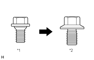 0.621,1.754 0.818,1.944 0.197,0.19 10 *1 2.535,1.754 2.732,1.944 0.197,0.19 10 *2
*1 Centering Bolt *2 Standard Bolt
Centering bolts are used to mount the door hinge to the vehicle body and door. The door cannot be adjusted with the centering bolts on. Substitute the centering bolts for standard bolts when making adjustments.
PROCEDURE

 1. PRECAUTION
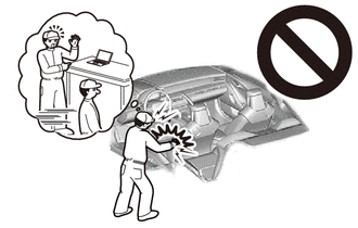
- CAUTION:
-
-
Be sure to read Precaution thoroughly before servicing.
- ·
for HV Model with Occupant Classification System:
·for Gasoline Model with Occupant Classification System:
·w/o Occupant Classification System:
- NOTICE:
-
After turning the ignition switch off, waiting time may be required before disconnecting the cable from the negative (-) auxiliary battery terminal. Therefore, make sure to read the disconnecting the cable from the negative (-) auxiliary battery terminal notices before proceeding with work.
-
Click hereGeneral>INTRODUCTION>REPAIR INSTRUCTION>PRECAUTION
58410B
2.REMOVE DECK BOARD ASSEMBLY (for HV Model)
58416K
3.REMOVE REAR NO. 2 FLOOR BOARD (for HV Model)
65351A
4.REMOVE BATTERY HOLE COVER (for HV Model)
5.DISCONNECT CABLE FROM NEGATIVE AUXILIARY BATTERY TERMINAL
for A25A-FXS:
Click hereGeneral>MAINTENANCE>A25A-FXS AUXILIARY BATTERY>REMOVAL
for A25A-FKS:
for M20A-FKS:
for A25B-FXS:
Click hereGeneral>MAINTENANCE>A25B-FXS AUXILIARY BATTERY>REMOVAL
- CAUTION:
-
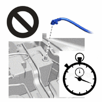
- ·
Wait at least 90 seconds after disconnecting the cable from the negative (-) auxiliary battery terminal to disable the SRS system.
·If the airbag deploys for any reason, it may cause a serious accident.
- NOTICE:
-
When disconnecting the cable, some systems need to be initialized after the cable is reconnected.
-
Click hereGeneral>INTRODUCTION>REPAIR INSTRUCTION>INITIALIZATION
6.INSPECT FRONT DOOR PANEL SUB-ASSEMBLY LH
Check that the clearance measurements of areas A to L are within the standard ranges.
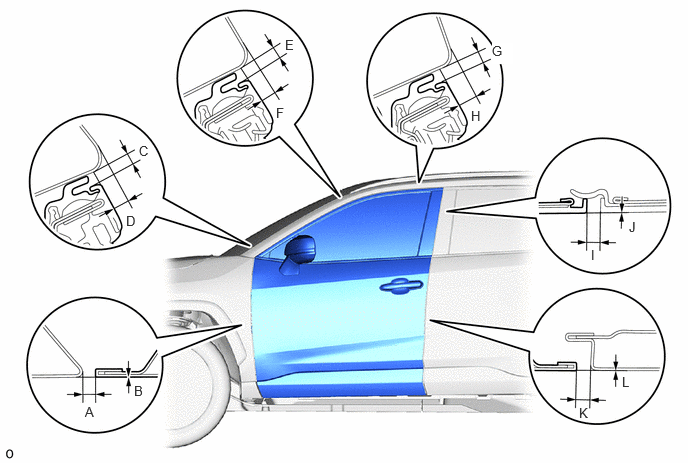
- Standard Clearance:
Area Measurement Area Measurement A 2.5 to 5.5 mm (0.0984 to 0.2165 in.) B -1.8 to 1.2 mm (-0.0709 to 0.0472 in.) C 2.65 to 6.05 mm (0.104 to 0.238 in.) D 2.35 to 6.35 mm (0.0925 to 0.2500 in.) E 2.65 to 6.05 mm (0.104 to 0.238 in.) F 1.65 to 6.15 mm (0.0650 to 0.2421 in.) G 2.65 to 6.05 mm (0.104 to 0.238 in.) H 3.75 to 7.85 mm (0.148 to 0.309 in.) I
(Reference)5.1 mm (0.201 in.) J
(Reference)0 mm (0 in.) K 2.9 to 5.3 mm (0.114 to 0.209 in.) L -1.5 to 0.9 mm (-0.0591 to 0.0354 in.)
7.ADJUST FRONT DOOR PANEL SUB-ASSEMBLY LH
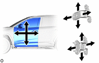
Using SST, loosen the hinge bolts on the body and adjust the door position.
- SST
- 09812-00010
Tighten the hinge bolts on the body after the adjustment.
- Torque:
- 26 N*m (265 kgf*cm, 19 ft.*lbf)
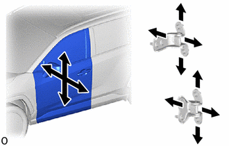
Loosen the hinge bolts on the door and adjust the door position.
Tighten the hinge bolts on the door after the adjustment.
- Torque:
- 21 N*m (214 kgf*cm, 15 ft.*lbf)
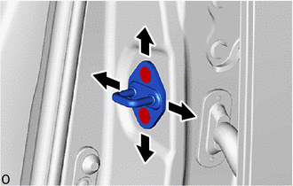
Using a T40 "TORX" socket wrench, adjust the striker position by slightly loosening the striker mounting screws and hitting the striker with a brass bar and a hammer.
Using a T40 "TORX" socket wrench, tighten the striker mounting screws after the adjustment.
- Torque:
- 23 N*m (235 kgf*cm, 17 ft.*lbf)
8.CONNECT CABLE TO NEGATIVE AUXILIARY BATTERY TERMINAL
for A25A-FXS:
Click hereGeneral>MAINTENANCE>A25A-FXS AUXILIARY BATTERY>INSTALLATION
for A25A-FKS:
for M20A-FKS:
for A25B-FXS:
Click hereGeneral>MAINTENANCE>A25B-FXS AUXILIARY BATTERY>INSTALLATION
- NOTICE:
-
When disconnecting the cable, some systems need to be initialized after the cable is reconnected.
-
Click hereGeneral>INTRODUCTION>REPAIR INSTRUCTION>INITIALIZATION
65351A
9.INSTALL BATTERY HOLE COVER (for HV Model)
58416K
10.INSTALL REAR NO. 2 FLOOR BOARD (for HV Model)
58410B
11.INSTALL DECK BOARD ASSEMBLY (for HV Model)
12.INSPECT SRS WARNING LIGHT
for HV Model with Occupant Classification System:
for Gasoline Model with Occupant Classification System:
w/o Occupant Classification System:
13. PERFORM DIAGNOSTIC SYSTEM CHECK
for HV Model with Occupant Classification System:
for Gasoline Model with Occupant Classification System:
w/o Occupant Classification System: