C54 MANUAL TRANSMISSION / TRANSAXLE MANUAL TRANSAXLE ASSEMBLY REMOVAL
PROCEDURE

 1.DRAIN TRANSAXLE OIL
2.REMOVE FRONT WIPER MOTOR AND LINK
55815E
3.REMOVE FRONT NO. 1 VENTILATOR SEAL (for LHD)
55815E
4.REMOVE FRONT NO. 1 VENTILATOR SEAL (for RHD)
55735D
5.REMOVE FRONT AIR SHUTTER SEAL RH (for LHD)
55735D
6.REMOVE FRONT AIR SHUTTER SEAL RH (for RHD)
55722C
7.REMOVE INNER COWL TOP TO COWL BRACE (for LHD)
55722C
8.REMOVE INNER COWL TOP TO COWL BRACE (for RHD)
55711
9.REMOVE OUTER COWL TOP PANEL (for LHD)
55711
10.REMOVE OUTER COWL TOP PANEL (for RHD)
17700
11.REMOVE AIR CLEANER ASSEMBLY
17771A
12.REMOVE AIR CLEANER BRACKET
28800
13.REMOVE BATTERY
74431
14.REMOVE BATTERY TRAY
74411
15.REMOVE BATTERY CARRIER (for LHD)
74411
16.REMOVE BATTERY CARRIER (for RHD)
28100
17.REMOVE STARTER ASSEMBLY (for 1NZ-FE)
28100
18.REMOVE STARTER ASSEMBLY (for 2NZ-FE)
31470
19.SEPARATE CLUTCH RELEASE CYLINDER ASSEMBLY
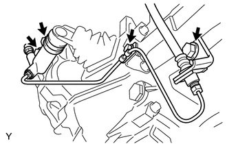
Remove the 4 bolts, then separate the clutch release cylinder assembly.
- HINT:
-
Suspend the clutch release cylinder assembly with a piece of rope so as not to overload the clutch pipe.
33820B
20.SEPARATE TRANSMISSION CONTROL CABLE ASSEMBLY
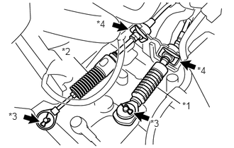
Remove the clip A and washer, and separate the control shift cable from the manual transaxle assembly.
| *1 | Control Shift Cable |
| *2 | Control Select Cable |
| *3 | Clip A |
| *4 | Clip B |
Remove the clip B from the control shift cable, and separate the control shift cable from the control cable bracket.
Remove the clip A and washer, and separate the control select cable from the manual transaxle assembly.
Remove the clip B from the control select cable, and separate the control select cable from the control cable bracket.
21.REMOVE CONTROL CABLE BRACKET
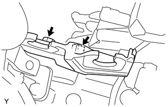
Remove the 2 bolts and the control cable bracket.
22.DISCONNECT WIRE HARNESS (w/ ABS)
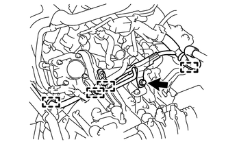
Separate the 4 clamps and remove the bolt, and separate the wire harness from the manual transaxle assembly.
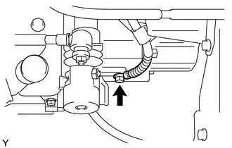
Remove the bolt and separate the ground wire.
Disconnect the back up light switch connector.
23.DISCONNECT WIRE HARNESS (w/o ABS)
Separate the 4 clamps and remove the bolt, and separate the wire harness from the manual transaxle assembly.
Remove the bolt and separate the ground wire.
Disconnect the back up light switch connector.
Disconnect the speedometer sensor connector.
43420
24.REMOVE FRONT DRIVE SHAFT ASSEMBLIES
51201
25.REMOVE FRONT SUSPENSION CROSSMEMBER SUB-ASSEMBLY
26.SUPPORT ENGINE AND TRANSAXLE
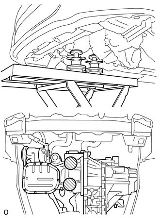
On a flat location, set the attachment, plate lift attachment, and wooden block in the positions shown in the figure, and set the engine assembly.

|
Attachment Placement Positions |
- NOTICE:
- ·
Set the engine assembly with transaxle so that it is horizontal.
·Never attach the attachment and plate lift attachment to the oil pan section of the engine assembly.
12313
27.REMOVE TRANSVERSE ENGINE ENGINE MOUNTING CONTROL BRACKET
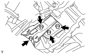
Remove the 4 bolts and the transverse engine engine mounting control bracket.
30300
28.SUPPORT MANUAL TRANSAXLE ASSEMBLY
Support the manual transaxle assembly with a transmission jack so that it is stable.
12372A
29.REMOVE TRANSVERSE ENGINE ENGINE MOUNTING INSULATOR
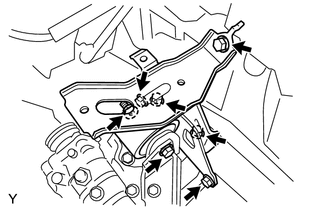
Remove the bolt and nut, then separate the transverse engine engine mounting insulator from the transverse engine engine mounting bracket.
- HINT:
-
Hold the nut and loosen the bolt.
Remove the 5 bolts and the transverse engine engine mounting insulator.
12325A
30.REMOVE TRANSVERSE ENGINE ENGINE MOUNTING BRACKET
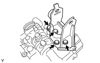
Remove the 4 bolts and the transverse engine engine mounting bracket from the manual transaxle assembly.
30300
31.REMOVE MANUAL TRANSAXLE ASSEMBLY
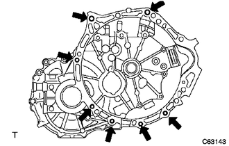
Remove the 7 bolts and the manual transaxle assembly.
- NOTICE:
- ·
To prevent damage to the knock pins, do not pry between the transaxle and engine.
·To avoid damage to the input shaft, do not forcefully shake the manual transaxle.
33403K
32.REMOVE SPEEDOMETER DRIVEN HOLE COVER SUB-ASSEMBLY (w/ ABS)
Remove the bolt and the speedometer driven hole cover sub-assembly from the manual transaxle assembly.
Remove the O-ring from the speedometer driven hole cover sub-assembly.
83181G
33.REMOVE SPEEDOMETER SENSOR (w/o ABS)
Remove the bolt and the speedometer sensor from the manual transaxle assembly.
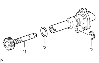
Remove the E-ring and the speedometer driven gear from the speedometer sensor.
| *1 | Speedometer Driven Gear |
| *2 | O-ring |
| *3 | E-ring |
Remove the O-ring from the speedometer sensor.
34.REMOVE WIRE HARNESS CLAMP BRACKET
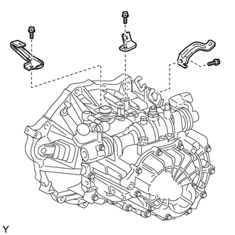
Remove the 3 bolts and the 3 wire harness clamp brackets from the manual transaxle assembly.