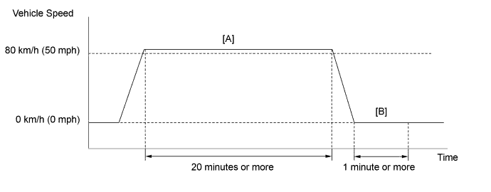
DTC P0171 System Too Lean (Bank 1) |
DTC P0172 System Too Rich (Bank 1) |
DTC P1170 Port Injector Fuel Performance |
DTC P117B Direct Injector Fuel Performance |
| DTC No. | DTC Detection Condition | Trouble Area |
| P0171 | With warm engine and stable air fuel ratio feedback, fuel trim considerably in error to lean side. (2 trip detection logic) |
|
| P0172 | With warm engine and stable air fuel ratio feedback, fuel trim considerably in error to rich side. (2 trip detection logic) |
|
| P1170 | Although a DTC is stored for a rich or lean condition, the amount of fuel trim during direct injection is normal for 9 seconds. (1 trip detection logic) |
|
| P117B | Although a DTC is stored for a rich or lean condition, the amount of fuel trim during port injection is normal for 9 seconds. (1 trip detection logic) |
|
| GTS Display | Description |
| NORMAL |
|
| ABNORMAL |
|
| INCOMPLETE |
|
| N/A |
|
| GTS Display (Sensor) | Injection Volume | Status | Voltage |
| AFS Voltage B1S1 (Air fuel ratio) | +12.5% | Rich | Below 2.0 V |
| -12.5% | Lean | Higher than 2.4 V | |
| O2S B1S2 (Heated oxygen) | +12.5% | Rich | Higher than 0.55 V |
| -12.5% | Lean | Below 0.4 V |
| Case | Air Fuel Ratio Sensor (Sensor 1) Output Voltage | Heated Oxygen Sensor (Sensor 2) Output Voltage | Main Suspected Trouble Area |
| 1 |   |  | - |
| 2 |  | |
|
| 3 | | |
|
| 4 | | |
|
| 1.CHECK ANY OTHER DTCS OUTPUT (IN ADDITION TO DTC P0171, P0172, P1170 AND/OR P117B) |
Connect the GTS to the DLC3.
Turn the ignition switch to ON.
Turn the GTS on.
Enter the following menus: Powertrain / Engine / Trouble Codes.
Read the DTCs.
| Result | Proceed to |
| P0171, P0172, P1170 or P117B | A |
| P0171, P0172, P1170 and/or P117B and other DTCs | B |
|
| ||||
| A | |
 |
| 2.PERFORM ACTIVE TEST USING GTS (CONTROL THE INJECTION VOLUME FOR A/F SENSOR) |
Connect the GTS to the DLC3.
Turn the ignition switch to ON.
Turn GTS on.
Warm up the engine and run the engine at an engine speed of 2500 rpm for approximately 90 seconds.
Enter the following menus: Powertrain / Engine / Active Test / Control the Injection Volume for A/F Sensor / AFS Voltage B1S1 and O2S B1S2.
Perform the Control the Injection Volume for A/F Sensor operation with the engine in an idling.
Monitor the output voltages of the A/F and HO2 sensors (AFS Voltage B1S1 and O2S B1S2) displayed on the GTS.
| GTS Display (Sensor) | Injection Volume | Status | Voltage |
| AFS Voltage B1S1 (A/F) | 12.5% | Rich | Less than 2.0 V |
| -12.5% | Lean | More than 2.4 V | |
| O2S B1S2 (HO2) | 12.5% | Rich | More than 0.55 V |
| -12.5% | Lean | Less than 0.4 V |
| Status AFS Voltage B1S1 | Status O2S B1S2 | A/F Condition and A/F Sensor Condition | Suspected Trouble Area | Proceed to |
| Lean/Rich | Lean/Rich | Normal | - | A |
| Lean | Lean | Actual air-fuel ratio lean |
| A |
| Rich | Rich | Actual air-fuel ratio rich |
| A |
| Lean | Lean/Rich | A/F sensor malfunction |
| B |
| Rich | Lean/Rich | A/F sensor malfunction |
| B |
|
| ||||
| A | |
|
| 3.CHECK FREEZE FRAME DATA |
Check freeze frame data, and understand the status of vehicles when abnormalities occur.
| Engine Speed | Fuel System Status #1 | O2S B1S2 |
| Calculate Load | Short FT #1 | Evap Purge Flow |
| Vehicle Speed | Long FT #1 | Shift Position Sig from ECT |
| MAF | AFS Voltage B1S1 | Coolant Temp |
| NEXT | |
|
| 4.CHECK VEHICLE CONDITION |
Remove the EFI (+B) fuse, wait 60 seconds or more, and connect the fuse.
Connect the GTS to the DLC3.
Turn the ignition switch to ON.
Turn GTS on.
Enter the following menus: Powertrain / Engine / Active Test / Control the Injection Volume.
Increase or decrease injection quantities by 1 step.
Start the engine.
Refer to the running state freeze frame data, reproduce the conditions in which the abnormality occurred, and check the trouble.
| Result | Proceed to |
| Trouble can be confirmed. | A |
| Trouble cannot be confirmed. | B |
|
| ||||
| A | |
|
| 5.CHECK VEHICLE CONDITION |
Specify the location of the trouble from the following, then conduct inspections and replacements.
| Trouble area | Symptom | Cause | Troubleshooting | Diagnostic note |
| Mass air flow meter |
| Deviation in characteristic of the mass air flow meter | Refer to Click here. | - |
| Fuel injector assembly (for port injection or direct injection) | MIL lights up only. | Fuel injector assembly blockage |
|
During driving, the MIL lights up often. |
| Problem with oil-tightness in fuel injector assembly |
|
| |
| Fuel pump assembly |
|
|
| - |
| Intake system |
| Air sucked in from the intake manifold gasket. | Check intake manifold gasket inspection. | - |
| Start the engine, and in idle condition block off individual hoses connected to the intake manifold, and check that the fuel compensation quantity (total of feedback compensated value and feedback learning value) decreases. | If air is being drawn into the hose, the fuel compensation quantity (total of feedback compensated value and feedback learning value) is large, and this drops with a racing condition. | ||
| Air fuel ratio sensor | Rough idling | Air fuel ratio sensor malfunction | Refer to Click here. | Air fuel ratio sensor system DTC may be stored. |
After the trouble area is repaired, Check that the trouble symptom is resolved.
| Result | Proceed to |
| Trouble symptom resolved | A |
| Trouble symptom not resolved | B |
|
| ||||
| A | |
|
| 6.CLEAR DTC |
Connect the GTS to the DLC3.
Turn the ignition switch to ON.
Turn the GTS on.
Clear the DTCs (Click here).
| NEXT | |
|
| 7.READ VALUE USING GTS (SHORT FT #1 AND LONG FT #1) |
Connect the GTS to the DLC3.
Turn the ignition switch to ON.
Turn the GTS on.
Start the engine.
Enter the following menus: Powertrain / Engine / Data List / Short #1, Long FT #1.
Read the value Short #1 and Long FT #1.
| GTS display | Condition | Specified condition |
| Short FT #1 + Long FT #1 | Vehicle condition when the malfunction occurs (Idling or driving) | -20% to +20% |
|
| ||||
| OK | |
|
| 8.CHECK VEHICLE CONDITION |
Check the diagnostic table and freeze frame data again, and if there is no abnormality, finish operations.
| NEXT | ||
 | ||
| ||
| 9.READ VALUE USING GTS (SHORT FT #1 AND LONG FT #1) |
Connect the GTS to the DLC3.
Start the engine.
Turn the GTS on.
Enter the following menus: Powertrain / Engine / Active Test / Control the Injection Way / Port.
Read the value Short FT #1 and Long FT #1.
| GTS display | Condition | Specified condition |
| Short FT #1 + Long FT #1 | Idling | -20% to +20% |
Enter the following menus: Powertrain / Engine / Active Test / Control the Injection Way / Direct.
Read the value Short FT #1 and Long FT #1.
| GTS display | Condition | Specified condition |
| Short FT #1 + Long FT #1 | Idling | -20% to +20% |
| Control the Injection Way | Proceed to | |
| Port | Direct | |
| OK | OK | A |
| OK | NG | B |
| NG | OK | C |
| NG | NG | D |
|
| ||||
|
| ||||
|
| ||||
| A | |
|
| 10.CHECK VEHICLE CONDITION |
Check the diagnostic table and freeze frame data again, and if there is no abnormality, finish operations.
| NEXT | ||
| ||
| ||
| 11.CHECK EMISSION CONTROL SYSTEM |
Check emission control system (Click here).
|
| ||||
| OK | |
|
| 12.CHECK INTAKE SYSTEM |
Check the intake system for vacuum leaks (Click here).
|
| ||||
| OK | |
|
| 13.INSPECT ENGINE COOLANT TEMPERATURE SENSOR |
Inspect the engine coolant temperature sensor (Click here).
|
| ||||
| OK | |
|
| 14.READ VALUE USING GTS (MAF) |
Connect the GTS to the DLC3.
Turn the ignition switch to ON.
Turn the GTS on.
Start the engine.
Enter the following menus: Powertrain / Engine / Data List / MAF.
Read MAF with the engine speed at 3000 rpm.
| GTS display | Condition | Specified condition |
| MAF | Engine speed at 3000 rpm | 8 to 13 g/s |
|
| ||||
| OK | |
|
| 15.CHECK IGNITION SYSTEM |
Check the ignition system (Click here).
|
| ||||
| OK | |
|
| 16.CHECK FOR EXHAUST GAS LEAK |
Check for exhaust gas leaks.
| Result | Proceed to |
| Abnormal | A |
| Normal | B |
|
| ||||
| A | ||
| ||
| ||
| 17.INSPECT AIR FUEL RATIO SENSOR |
Inspect the air fuel ratio sensor (Click here).
|
| ||||
| OK | |
|
| 18.CHECK HARNESS AND CONNECTOR (AIR FUEL RATIO SENSOR - ECM) |
Disconnect the air fuel ratio sensor connector.
Disconnect the ECM connector.
Measure the resistance according to the value(s) in the table below.
| Tester Connection | Condition | Specified Condition |
| A34-19 (A1A+) - C14-3 (A1A+) | Always | Below 1 Ω |
| A34-18 (A1A-) - C14-4 (A1A-) | Always | Below 1 Ω |
| A34-5 (HA1A) - C14-1 (HA1A) | Always | Below 1 Ω |
| Tester Connection | Condition | Specified Condition |
| A34-19 (A1A+) or C14-3 (A1A+) - Body ground | Always | 10 kΩ or higher |
| A34-18 (A1A-) or C14-4 (A1A-) - Body ground | Always | 10 kΩ or higher |
| A34-5 (HA1A) or C14-1 (HA1A) - Body ground | Always | 10 kΩ or higher |
|
| ||||
| OK | |
|
| 19.REPLACE AIR FUEL RATIO SENSOR |
Replace the air fuel ratio sensor (Click here).
| NEXT | |
|
| 20.READ VALUE USING GTS (SHORT FT #1 AND LONG FT #1) |
Connect the GTS to the DLC3.
Turn the ignition switch to ON.
Turn the GTS on.
Start the engine.
Enter the following menus: Powertrain / Engine / Data List / Short FT #1, Long FT #1.
Read the value displayed on the GTS.
| GTS display | Condition | Specified condition |
| Short FT #1 + Long FT #1 | Idling or racing | -20% to +20% |
|
| ||||
| OK | ||
| ||
| ||
| 21.CHECK FUEL PRESSURE (LOW PRESSURE SIDE) |
Check the fuel pressure (low pressure side) .
| Result | Proceed to |
| Abnormal | A |
| Normal | B |
|
| ||||
| A | ||
| ||
| ||
| 22.READ VALUE USING GTS (FUEL PRESS) |
Connect the GTS to the DLC3.
Turn the ignition switch to ON.
Turn the GTS on.
Start the engine.
Enter the following menus: Powertrain / Engine / Data List / Fuel Press.
Read the value displayed on the GTS.
| GTS display | Condition | Specified condition |
| Fuel Press | Idling | 3000 to 5000 kPa (30.6 to 50.9 kgf/cm2, 436 to 725 psi) |
|
| ||||
| OK | |
|
| 23.PERFORM ACTIVE TEST USING GTS (CONTROL THE INJECTION WAY) |
Connect the GTS to the DLC3.
Start the engine.
Turn the GTS on.
Enter the following menus: Powertrain / Engine / Active Test / Control the Injection Way / Direct.
Read the value Fuel Press Target Value, Short FT #1 and Long FT #1.
| GTS display | Condition | Proceed to | |
| Fuel Pressure Target Value | Short FT #1 + Long FT #1 | ||
| 3 to 5 MPa (30.6 to 50.9 kgf/cm2, 436 to 725 psi) | - | Idling | A |
| 5 MPa (50.9 kgf/cm2, 725 psi) or more | +20% or more | B | |
| 5 MPa (50.9 kgf/cm2, 725 psi) or more | -20% or less | C | |
| 3 MPa (30.6 kgf/cm2, 436 psi) or less | +20% or more | C | |
| 3 MPa (30.6 kgf/cm2, 436 psi) or less | -20% or less | D | |
|
| ||||
|
| ||||
|
| ||||
| A | |
|
| 24.PERFORM ACTIVE TEST USING GTS (CONTROL THE INJECTION WAY) |
Connect the GTS to the DLC3.
Start the engine.
Turn the GTS on.
Enter the following menus: Powertrain / Engine / Active Test / Control the Injection Way / Direct.
Read the value Fuel Press Target Value, Short FT #1 and Long FT #1.
| GTS display | Condition | Proceed to | |
| Fuel Pressure Target Value | Short FT #1 + Long FT #1 | ||
| 3 to 5 MPa (30.6 to 50.9 kgf/cm2, 436 to 725 psi) | -25% or less | Idling | A |
| 3 to 5 MPa (30.6 to 50.9 kgf/cm2, 436 to 725 psi) | +30% or more | ||
| 5 MPa (50.9 kgf/cm2, 725 psi) or more | -25% to 25% | B | |
|
| ||||
| A | ||
| ||
| ||
| 25.READ VALUE USING GTS (FUEL PRESS) |
Connect the GTS to the DLC3.
Turn the ignition switch to ON.
Turn the GTS on.
Start the engine.
Enter the following menus: Powertrain / Engine / Data List / Fuel Press.
Read the value displayed on the GTS.
| GTS display | Condition | Specified condition |
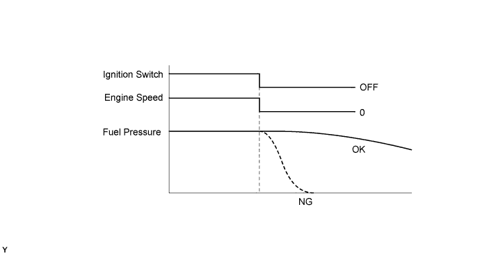
| Fuel Press | Engine running → Ignition switch OFF → Ignition switch ON | Fuel Press value decrease moderately. |
| Result | Proceed to |
| Fuel pressure rises or drops moderately. | A |
| Fuel pressure drops immediately after turning the ignition switch off. | B |
|
| ||||
| A | ||
| ||
| ||
| 26.INSPECT FUEL INJECTOR ASSEMBLY (FOR PORT INJECTION) |
Inspect the fuel injector assembly (for port injection) (Click here).
|
| ||||
| OK | ||
| ||
| ||
| 27.CHECK HARNESS AND CONNECTOR (MASS AIR FLOW METER CONNECTOR CONNECTION) |
Check the connection and terminal contact pressure of connectors and wire harness between the mass air flow meter and ECM (Click here).
| NEXT | |
|
| 28.CLEAR DTC |
Connect the GTS to the DLC3.
Turn the ignition switch to ON.
Turn the GTS on.
Clear the DTCs (Click here).
| NEXT | |
|
| 29.READ VALUE USING GTS (SHORT FT #1 AND LONG FT #1) |
Connect the GTS to the DLC3.
Turn the ignition switch to ON.
Turn the GTS on.
Start the engine.
Enter the following menus: Powertrain / Engine / Data List / Short FT #1, Long FT #1
Read the value displayed on the GTS.
| GTS display | Condition | Specified condition |
| Short FT #1 + Long FT #1 | Vehicle condition when the malfunction occurs (Idling or driving) | -20% to +20% |
|
| ||||
| OK | ||
| ||
| ||
| 30.CHECK HARNESS AND CONNECTOR (MASS AIR FLOW METER - ECM) |
Disconnect the mass air flow meter connector.
Disconnect the ECM connector.
Measure the resistance according to the value(s) in the table below.
| Tester Connection | Condition | Specified Condition |
| A33-22 (VG) - C16-5 (VG) | Always | Below 1 Ω |
| A33-29 (E2G) - C16-4 (E2G) | Always | Below 1 Ω |
| Tester Connection | Condition | Specified Condition |
| A33-22 (VG) or C16-5 (VG) - Body ground | Always | 10 kΩ or higher |
| A33-29 (E2G) or C16-4 (E2G) - Body ground | Always | 10 kΩ or higher |
|
| ||||
| OK | |
|
| 31.REPLACE MASS AIR FLOW METER |
Replace the mass air flow meter (Click here).
| NEXT | |
|
| 32.CLEAR DTC |
Connect the GTS to the DLC3.
Turn the ignition switch to ON.
Turn the GTS on.
Clear the DTCs (Click here).
| NEXT | |
|
| 33.READ VALUE USING GTS (SHORT FT #1 AND LONG FT #1) |
Connect the GTS to the DLC3.
Turn the ignition switch to ON.
Turn the GTS on.
Start the engine.
Enter the following menus: Powertrain / Engine / Data List / Short FT #1, Long FT #1.
Read the value displayed on the GTS.
| GTS display | Condition | Specified condition |
| Short FT #1 + Long FT #1 | Idling or racing | -20% to +20% |
|
| ||||
| OK | ||
| ||
| ||

