A4R AUTOMATIC TRANSMISSION / TRANSAXLE AUTOMATIC TRANSMISSION SYSTEM P0730 Gear Ratio Malfunction
DESCRIPTION
The ECM receives signals from the transmission revolution sensor (input speed sensor) and the transmission revolution sensor (output speed sensor), and determines the optimum gear according to the driving condition. Additionally, the ECM monitors the difference in rotation between the input shaft speed (turbine speed) and the output shaft speed (output speed).
During driving, if the difference between the gear ratio and the ratio of turbine speed to output speed is detected for at least a certain period of time, the DTC is stored.
| DTC No. | Detection Item | DTC Detection Condition | Trouble Area | MIL | Warning Indicate | Memory | Note |
|---|---|---|---|---|---|---|---|
| P0730 | Gear Ratio Malfunction | 1. Diagnosis Condition 2. Malfunction Status 3. Malfunction Time 4. Other
1.
The vehicle is being driven. 2.
The ratio of turbine speed to output speed differs from the gear ratio. 3.
4 seconds 4.
2-trip detection logic |
·
Transmission revolution sensor (input speed sensor) ·
Transmission revolution sensor (output speed sensor) ·
ATF fluid level ·
Transmission control cable assembly ·
Open or short in transmission revolution sensor (input speed sensor) circuit ·
Open or short in transmission revolution sensor (output speed sensor) circuit ·
Oil strainer sub-assembly ·
Transmission valve body assembly ·
ECM ·
Automatic transmission assembly |
Come on | Blinks | DTC stored | - |
MIL:"Comes on" means the MIL (Malfunction Indicator Light) illuminates.
Memory:"DTC stored" means the ECM stores the trouble code if the ECU detects the DTC detection condition.
PROCEDURE
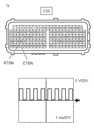
| *a | Rear view of wire harness connector
(to ECM) |
Using an oscilloscope, check the waveform.
- Waveform:
ECM Terminal Name C50-69 (RTBN) - C50-91 (ETBN) Tester Range 5 V/DIV., 1 ms./DIV. Condition Engine idling speed
- HINT:
-
As the engine speed becomes higher, the frequency becomes shorter.
- Result:
Proceed to OK NG
OK
NG
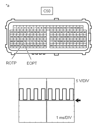
| *a | Rear view of wire harness connector
(to ECM) |
Using an oscilloscope, check the waveform.
- Waveform:
ECM Terminal Name C50-70 (ROTP) - C50-92 (EOPT) Tester Range 5 V/DIV., 1 ms./DIV. Condition Vehicle speed 20 km/h (12 mph)
- HINT:
-
As the engine speed becomes higher, the frequency becomes shorter.
- Result:
Proceed to OK NG
OK
NG
Check the automatic transmission fluid level.
Click hereDrivetrain>A4R AUTOMATIC TRANSMISSION / TRANSAXLE>AUTOMATIC TRANSMISSION FLUID>ON-VEHICLE INSPECTION
- OK:
Automatic transmission fluid level is correct.
- Result:
Proceed to OK NG
OK
NG
Check the joint section between the transmission control cable assembly and the transmission control shaft lever for wear. Also, check other joint sections for wear or deformation.
Check that the park/neutral position switch assembly is installed properly.
- Result:
Proceed to OK NG
OK
NG
Drive with the transmission wire disconnected. Shift the shift lever into each position to check whether the gear position changes as shown in the table below.
Click hereDrivetrain>A4R AUTOMATIC TRANSMISSION / TRANSAXLE>AUTOMATIC TRANSMISSION SYSTEM>MANUAL SHIFTING TEST
- Result:
Proceed to OK NG
OK
NG
Inspect the ECM power source circuit.
for 1NR-VE: Click hereEngine / Hybrid System>1NR-VE ENGINE CONTROL>SFI SYSTEM>ECM Power Source Circuit
for 2NR-VE w/ Air Fuel Ratio Sensor: Click hereEngine / Hybrid System>2NR-VE ENGINE CONTROL>SFI SYSTEM(w/ Air Fuel Ratio Sensor)>ECM Power Source Circuit
for 2NR-VE w/o Air Fuel Ratio Sensor: Click hereEngine / Hybrid System>2NR-VE ENGINE CONTROL>SFI SYSTEM(w/o Air Fuel Ratio Sensor)>ECM Power Source Circuit
- Result:
Result Proceed to OK (for 1NR-VE) A OK (for 2NR-VE) B NG C
A
B
C
Replace the oil strainer sub-assembly.
Click hereDrivetrain>A4R AUTOMATIC TRANSMISSION / TRANSAXLE>VALVE BODY ASSEMBLY>REMOVAL
Check the O-ring (oil strainer sub-assembly) for wear or damage.
- Result:
The O-ring (oil strainer sub-assembly) is not worn or deformed.
- Result:
Proceed to OK NG
OK
NG
Check that the groove in the manual valve is aligned with the hole (N position) in the valve body.
Click hereDrivetrain>A4R AUTOMATIC TRANSMISSION / TRANSAXLE>VALVE BODY ASSEMBLY>INSTALLATION
- Result:
Proceed to OK NG
OK
NG
Check each solenoid valve.
Click hereDrivetrain>A4R AUTOMATIC TRANSMISSION / TRANSAXLE>VALVE BODY ASSEMBLY>INSPECTION
- Result:
Proceed to OK NG
OK
NG
Replace the transmission valve body assembly.
Click hereDrivetrain>A4R AUTOMATIC TRANSMISSION / TRANSAXLE>VALVE BODY ASSEMBLY>REMOVAL
- Result:
Proceed to NEXT
NEXT
Connect the GTS or Techstream to the DLC3.
Start the engine and turn the GTS or Techstream on.
Clear the DTCs.
Enter the following menus: Powertrain / A/T / Trouble Codes.
- Powertrain > A/T > Trouble Codes
- 50001 565
Refer to Road Test.
Click hereDrivetrain>A4R AUTOMATIC TRANSMISSION / TRANSAXLE>AUTOMATIC TRANSMISSION SYSTEM>ROAD TEST
Read the DTCs using the GTS or Techstream.
- HINT:
-
When not using the GTS or Techstream, refer to DTC CHECK / CLEAR.
-
Click hereDrivetrain>A4R AUTOMATIC TRANSMISSION / TRANSAXLE>AUTOMATIC TRANSMISSION SYSTEM>DTC CHECK / CLEAR
- Result:
Result proceed to DTC not output. A DTC C1730 is output. B
A
B
Disconnect the C43 transmission revolution sensor (output speed sensor) connector.
Disconnect the C50 ECM connector.
Measure the resistance according to the value(s) in the table below.
- Standard Resistance (Check for Open):
Tester Connection Condition Specified Condition C43-1 (VCC) - C50-48 (VBOP) Always Below 1 Ω C43-2 (VOUT) - C50-70 (ROPT) Always Below 1 Ω C43-3 (GND) - C50-92 (EOPT) Always Below 1 Ω
- Standard Resistance (Check for Short):
Tester Connection Condition Specified Condition C43-1 (VCC) or C50-48 (VBOP) - Body ground and other terminals Always 10 kΩ or higher C43-2 (VOUT) or C50-70 (ROPT) - Body ground and other terminals Always 10 kΩ or higher C43-3 (GND) or C50-92 (EOPT) - Body ground and other terminals Always 10 kΩ or higher
Reconnect the C43 transmission revolution sensor (output speed sensor) connector.
Reconnect the C50 ECM connector.
- Result:
Proceed to OK NG
OK
NG
Disconnect the C44 transmission revolution sensor (input speed sensor) connector.
Disconnect the C50 ECM connector.
Measure the resistance according to the value(s) in the table below.
- Standard Resistance (Check for Open):
Tester Connection Condition Specified Condition C44-1 (VCC) - C50-47 (VBTB) Always Below 1 Ω C44-2 (VOUT) - C50-69 (RTBN) Always Below 1 Ω C44-3 (GND) - C50-91 (ETBN) Always Below 1 Ω
- Standard Resistance (Check for Short):
Tester Connection Condition Specified Condition C44-1 (VCC) or C50-47 (VBTB) - Body ground and other terminals Always 10 kΩ or higher C44-2 (VOUT) or C50-69 (RTBN) - Body ground and other terminals Always 10 kΩ or higher C44-3 (GND) or C50-91 (ETBN) - Body ground and other terminals Always 10 kΩ or higher
Reconnect the C44 transmission revolution sensor (input speed sensor) connector.
Reconnect the C50 ECM connector.
- Result:
Proceed to OK NG
OK
NG