NAVIGATION / MULTI INFO DISPLAY NAVIGATION SYSTEM(for Radio and Display Type) B15C3 Speaker Output Short
DESCRIPTION
This DTC is stored when a malfunction occurs in the speakers.
| DTC Code | DTC Detection Condition | Trouble Area |
|---|---|---|
| B1579 | Telephone microphone signal is lost. | ·
Radio and display receiver assembly ·
Map light assembly ·
Telephone microphone assembly ·
Telematics transceiver* ·
Harness or connector |
*: w/ Telematics Transceiver
WIRING DIAGRAM
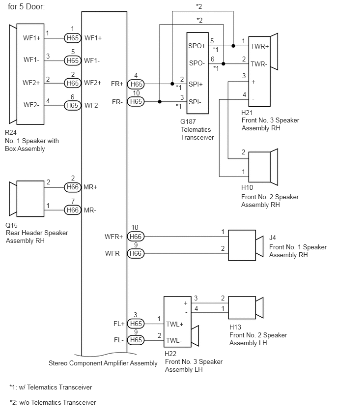
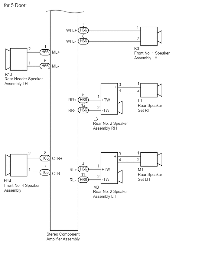
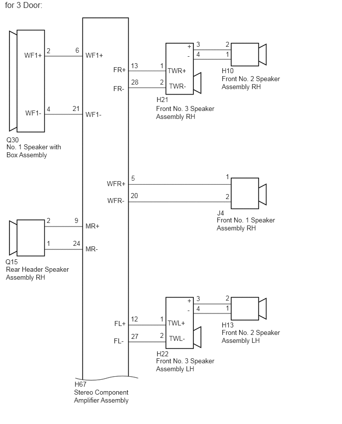
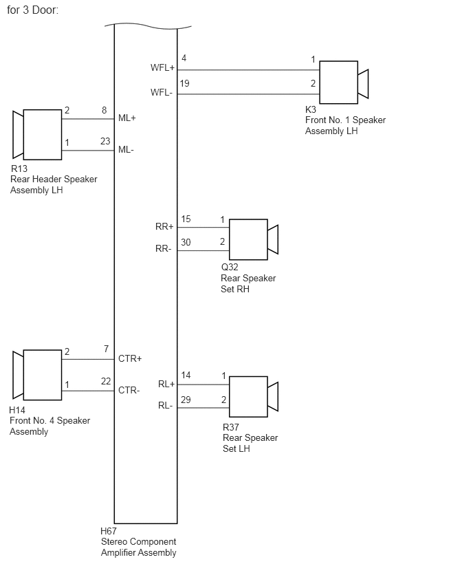
CAUTION / NOTICE / HINT
- HINT:
-
When replacing telematics transceiver, perform the vehicle contract setting.
PROCEDURE
- OK:
No DTCs are output.
- Result:
Proceed OK NG
OK
Click hereGeneral>INTRODUCTION>HOW TO TROUBLESHOOT ECU CONTROLLED SYSTEMS>HOW TO PROCEED WITH TROUBLESHOOTING
NG
Check the vehicle condition.
- Result:
Result Proceed to for 5 Door A for 3 Door B
A
B
*1: for RH Side
*2: for LH Side
*3: w/ Telematics Transceiver
*4: w/o Telematics Transceiver
Disconnect the J4*1 and/or K3*2 front No. 1 speaker assembly connector.
Disconnect the H10*1 and/or H13*2 front No. 2 speaker assembly connector.
Disconnect the H21*1 and/or H22*2 front No. 3 speaker assembly connector.
Disconnect the H14 front No. 4 speaker assembly connector.
Disconnect the L1*1 and/or M1*2 rear speaker set connector.
Disconnect the L3*1 and/or M3*2 rear No. 2 speaker assembly connector.
Disconnect the Q15*1 and/or R13*2 rear header speaker assembly connector.
Disconnect the R24 No. 1 speaker with box assembly connector.
Disconnect the H65 and H66 stereo component amplifier assembly connectors.
Disconnect the G187 telematics transceiver connector.*3
Measure the resistance according to the value(s) in the table below.
- Standard Resistance:
for RH Side: Tester Connection Condition Specified Condition H65-4 (FR+) - G187-2 (SPI+)*3 Always Below 1 Ω H65-10 (FR-) - G187-2 (SPI-)*3 Always Below 1 Ω H65-4 (FR+) - H21-1 (TWR+)*4 Always Below 1 Ω H65-10 (FR-) - H21-2 (TWR-)*4 Always Below 1 Ω G187-5 (SPO+) - H21-1 (TWR+)*3 Always Below 1 Ω G187-6 (SPO-) - H21-2 (TWR-)*3 Always Below 1 Ω H21-3 (+) - H10-2 Always Below 1 Ω H21-4 (-) - H10-1 Always Below 1 Ω H66-10 (WFR+) - J4-1 Always Below 1 Ω H66-9 (WFR-) - J4-2 Always Below 1 Ω H66-2 (MR+) - Q15-2 Always Below 1 Ω H66-7 (MR-) - Q15-1 Always Below 1 Ω H66-5 (RR+) - L3-1 (+TW) Always Below 1 Ω H66-12 (RR-) - L3-2 (-TW) Always Below 1 Ω L3-3 (+) - L1-1 Always Below 1 Ω L3-4 (-) - L1-2 Always Below 1 Ω H65-4 (FR+) - Body ground Always 10 kΩ or higher H65-10 (FR-) - Body ground Always 10 kΩ or higher G187-5 (SPO+) - Body ground*3 Always 10 kΩ or higher G187-6 (SPO-) - Body ground*3 Always 10 kΩ or higher H21-3 (+) - Body ground Always 10 kΩ or higher H21-4 (-) - Body ground Always 10 kΩ or higher H66-10 (WFR+) - Body ground Always 10 kΩ or higher H66-9 (WFR-) - Body ground Always 10 kΩ or higher H66-2 (MR+) - Body ground Always 10 kΩ or higher H66-7 (MR-) - Body ground Always 10 kΩ or higher H66-5 (RR+) - Body ground Always 10 kΩ or higher H66-12 (RR-) - Body ground Always 10 kΩ or higher L3-3 (+) - Body ground Always 10 kΩ or higher L3-4 (-) - Body ground Always 10 kΩ or higher
- Standard Resistance:
for LH Side: Tester Connection Condition Specified Condition H65-3 (FL+) - H22-1 (TWL+) Always Below 1 Ω H65-9 (FL-) - H22-2 (TWL-) Always Below 1 Ω H22-3 (+) - H13-2 Always Below 1 Ω H22-4 (-) - H13-1 Always Below 1 Ω H66-3 (WFL+) - K3-1 Always Below 1 Ω H66-8 (WFL-) - K3-2 Always Below 1 Ω H66-4 (RL+) - M3-1 (+TW) Always Below 1 Ω H66-11 (RL-) - M3-2 (-TW) Always Below 1 Ω M3-3 (+) - M1-1 Always Below 1 Ω M3-4 (-) - M1-2 Always Below 1 Ω H66-1 (ML+) - R13-2 Always Below 1 Ω H66-6 (ML-) - R13-1 Always Below 1 Ω H65-3 (FL+) - Body ground Always 10 kΩ or higher H65-9 (FL-) - Body ground Always 10 kΩ or higher H22-3 (+) - Body ground Always 10 kΩ or higher H22-4 (-) - Body ground Always 10 kΩ or higher H66-3 (WFL+) - Body ground Always 10 kΩ or higher H66-8 (WFL-) - Body ground Always 10 kΩ or higher H66-4 (RL+) - Body ground Always 10 kΩ or higher H66-11 (RL-) - Body ground Always 10 kΩ or higher M3-3 (+) - Body ground Always 10 kΩ or higher M3-4 (-) - Body ground Always 10 kΩ or higher H66-1 (ML+) - Body ground Always 10 kΩ or higher H66-6 (ML-) - Body ground Always 10 kΩ or higher
- Standard Resistance:
for Center Side: Tester Connection Condition Specified Condition H65-1 (WF1+) - R24-1 (WF1+) Always Below 1 Ω H65-5 (WF1-) - R24-3 (WF1-) Always Below 1 Ω H65-2 (WF2+) - R24-2 (WF2+) Always Below 1 Ω H65-6 (WF2-) - R24-4 (WF2-) Always Below 1 Ω H65-8 (CTR+) - H14-2 Always Below 1 Ω H65-7 (CTR-) - H14-1 Always Below 1 Ω H65-1 (WF1+) - Body ground Always 10 kΩ or higher H65-5 (WF1-) - Body ground Always 10 kΩ or higher H65-2 (WF2+) - Body ground Always 10 kΩ or higher H65-6 (WF2-) - Body ground Always 10 kΩ or higher H65-8 (CTR+) - Body ground Always 10 kΩ or higher H65-7 (CTR-) - Body ground Always 10 kΩ or higher
- Result:
Proceed to OK NG
OK
NG
Remove the front No. 1 speaker assembly.
Click hereAudio / Visual / Telematics>AUDIO / VIDEO>FRONT DOOR SPEAKER>REMOVAL
Inspect the front No. 1 speaker assembly.
Click hereAudio / Visual / Telematics>AUDIO / VIDEO>FRONT DOOR SPEAKER>INSPECTION
- Result:
Proceed to OK NG
OK
NG
Remove the front No. 2 speaker assembly.
Click hereAudio / Visual / Telematics>AUDIO / VIDEO>INSTRUMENT PANEL SPEAKER>REMOVAL
Inspect the front No. 2 speaker assembly.
Click hereAudio / Visual / Telematics>AUDIO / VIDEO>INSTRUMENT PANEL SPEAKER>INSPECTION
- Result:
Proceed to OK NG
OK
NG
Replace the front No. 3 speaker assembly with a known good one.
Click hereAudio / Visual / Telematics>AUDIO / VIDEO>PILLAR SPEAKER>REMOVAL
Check for DTCs and check if the same DTCs is output.
- NOTICE:
- ·
Connect all the connectors that were disconnected to the front No. 3 speaker assemblies.
·Perform the above inspection on both LH and RH sides.
- OK:
No DTCs are output.
- Result:
Proceed to OK NG (w/ Telematics Transceiver) NG (w/o Telematics Transceiver)
OK
NG (w/ Telematics Transceiver)
NG (w/o Telematics Transceiver)
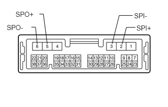
Remove the telematics transceiver.
Click hereAudio / Visual / Telematics>TELEMATICS>TELEMATICS TRANSCEIVER>REMOVAL
Measure the resistance according to the value(s) in the table below.
- Standard Resistance:
Tester Connection Condition Specified Condition 2 (SPI+) - 5 (SPO+) Always Below 1 Ω 3 (SPI-) - 6 (SPO-) Always Below 1 Ω 2 (SPI+) - Body ground Always 10 kΩ or higher 3 (SPI-) - Body ground Always 10 kΩ or higher
- Result:
Proceed to OK NG
OK
NG
Replace the front No. 4 speaker assembly with a known good one.
Click hereAudio / Visual / Telematics>AUDIO / VIDEO>INSTRUMENT PANEL SPEAKER>REMOVAL
Check for DTCs and check if the same DTCs is output.
- OK:
No DTCs are output.
- Result:
Result OK NG
OK
NG
Remove the rear speaker set.
Click hereAudio / Visual / Telematics>AUDIO / VIDEO>REAR DOOR SPEAKER>REMOVAL
Inspect the rear speaker set.
Click hereAudio / Visual / Telematics>AUDIO / VIDEO>REAR DOOR SPEAKER>INSPECTION
- Result:
Proceed to OK NG
OK
NG
Replace the rear No. 2 speaker assembly with a known good one.
Click hereAudio / Visual / Telematics>AUDIO / VIDEO>REAR DOOR SPEAKER>REMOVAL
Check for DTCs and check if the same DTCs is output.
- NOTICE:
- ·
Connect all the connectors that were disconnected to the rear No. 2 speaker assemblies.
·Perform the above inspection on both LH and RH sides.
- OK:
No DTCs are output.
- Result:
Proceed OK NG
OK
NG
Replace the rear header speaker assembly with a known good one.
Click hereAudio / Visual / Telematics>AUDIO / VIDEO>LUGGAGE SPEAKER (for 5 Door)>REMOVAL
Check for DTCs and check if the same DTCs is output.
- NOTICE:
- ·
Connect all the connectors that were disconnected to the rear header speaker assemblies.
·Perform the above inspection on both LH and RH sides.
- OK:
No DTCs are output.
- Result:
Proceed OK NG
OK
NG
Remove the No. 1 woofer box speaker assembly.
Click hereAudio / Visual / Telematics>AUDIO / VIDEO>LUGGAGE SPEAKER (for 5 Door)>REMOVAL
Inspect the No. 1 woofer box speaker assembly.
Click hereAudio / Visual / Telematics>AUDIO / VIDEO>LUGGAGE SPEAKER (for 5 Door)>INSPECTION
- Result:
Proceed OK NG
OK
NG
Replace the stereo component amplifier assembly with a known good one.
Click hereAudio / Visual / Telematics>AUDIO / VIDEO>STEREO COMPONENT AMPLIFIER>REMOVAL
Check for DTCs and check if the same DTCs is output.
- OK:
No DTCs are output.
- Result:
Proceed OK NG
OK
NG
Click hereAudio / Visual / Telematics>AUDIO / VIDEO>RADIO RECEIVER (for Radio and Display Type)>REMOVAL
*1: for RH Side
*2: for LH Side
Disconnect the J4*1 and/or K3*2 front No. 1 speaker assembly connector.
Disconnect the H10*1 and/or H13*2 front No. 2 speaker assembly connector.
Disconnect the H21*1 and/or H22*2 front No. 3 speaker assembly connector.
Disconnect the H14 front No. 4 speaker assembly connector.
Disconnect the Q32*1 and/or R37*2 rear speaker set connector.
Disconnect the Q15*1 and/or R13*2 rear header speaker assembly connector.
Disconnect the Q30 No. 1 speaker with box assembly connector.
Disconnect the H67 stereo component amplifier assembly connector.
Measure the resistance according to the value(s) in the table below.
- Standard Resistance:
Tester Connection Condition Specified Condition H67-13 (FR+) - H21-1 (TWR+)*1 Always Below 1 Ω H67-28 (FR-) - H21-2 (TWR-)*1 Always Below 1 Ω H21-3 (+) - H10-2*1 Always Below 1 Ω H21-4 (-) - H10-1*1 Always Below 1 Ω H67-5 (WFR+) - J4-1*1 Always Below 1 Ω H67-20 (WFR-) - J4-2*1 Always Below 1 Ω H67-12 (FL+) - H22-1 (TWL+)*2 Always Below 1 Ω H67-27 (FL-) - H22-2 (TWL-)*2 Always Below 1 Ω H22-3 (+) - H13-2*2 Always Below 1 Ω H22-4 (-) - H13-1*2 Always Below 1 Ω H67-6 (WF1+) - Q30-2 (WF1+) Always Below 1 Ω H67-21 (WF1-) - Q30-4 (WF1-) Always Below 1 Ω H67-9 (MR+) - Q15-2*1 Always Below 1 Ω H67-24 (MR-) - Q15-1*1 Always Below 1 Ω H67-4 (WFL+) - K3-1*2 Always Below 1 Ω H67-19 (WFL-) - K3-2*2 Always Below 1 Ω H67-15 (RR+) - Q32-1*1 Always Below 1 Ω H67-30 (RR-) - Q32-2*1 Always Below 1 Ω H67-14 (RL+) - R37-1*2 Always Below 1 Ω H67-29 (RL-) - R37-2*2 Always Below 1 Ω H67-8 (ML+) - R13-2*2 Always Below 1 Ω H67-23 (ML-) - R13-1*2 Always Below 1 Ω H67-7 (CTR+) - H14-2 Always Below 1 Ω H67-22 (CTR-) - H14-1 Always Below 1 Ω H67-13 (FR+) - Body ground*1 Always 10 kΩ or higher H67-28 (FR-) - Body ground*1 Always 10 kΩ or higher H21-3 (+) - Body ground*1 Always 10 kΩ or higher H21-4 (-) - Body ground*1 Always 10 kΩ or higher H67-5 (WFR+) - Body ground*1 Always 10 kΩ or higher H67-20 (WFR-) - Body ground*1 Always 10 kΩ or higher H67-12 (FL+) - Body ground*2 Always 10 kΩ or higher H67-27 (FL-) - Body ground*2 Always 10 kΩ or higher H22-3 (+) - Body ground*2 Always 10 kΩ or higher H22-4 (-) - Body ground*2 Always 10 kΩ or higher H67-6 (WF1+) - Body ground Always 10 kΩ or higher H67-21 (WF1-) - Body ground Always 10 kΩ or higher H67-9 (MR+) - Body ground*1 Always 10 kΩ or higher H67-24 (MR-) - Body ground*1 Always 10 kΩ or higher H67-4 (WFL+) - Body ground*2 Always 10 kΩ or higher H67-19 (WFL-) - Body ground*2 Always 10 kΩ or higher H67-15 (RR+) - Body ground*1 Always 10 kΩ or higher H67-30 (RR-) - Body ground*1 Always 10 kΩ or higher H67-14 (RL+) - Body ground*2 Always 10 kΩ or higher H67-29 (RL-) - Body ground*2 Always 10 kΩ or higher H67-8 (ML+) - Body ground*2 Always 10 kΩ or higher H67-23 (ML-) - Body ground*2 Always 10 kΩ or higher H67-7 (CTR+) - Body ground Always 10 kΩ or higher H67-22 (CTR-) - Body ground Always 10 kΩ or higher
- Result:
Proceed to OK NG
OK
NG
Remove the front No. 1 speaker assembly.
Click hereAudio / Visual / Telematics>AUDIO / VIDEO>FRONT DOOR SPEAKER>REMOVAL
Inspect the front No. 1 speaker assembly.
Click hereAudio / Visual / Telematics>AUDIO / VIDEO>FRONT DOOR SPEAKER>INSTALLATION
- Result:
Proceed to OK NG
OK
NG
Remove the front No. 2 speaker assembly.
Click hereAudio / Visual / Telematics>AUDIO / VIDEO>INSTRUMENT PANEL SPEAKER>REMOVAL
Inspect the front No. 2 speaker assembly.
Click hereAudio / Visual / Telematics>AUDIO / VIDEO>INSTRUMENT PANEL SPEAKER>INSPECTION
- Result:
Proceed to OK NG
OK
NG
Replace the front No. 3 speaker assembly with a known good one.
Click hereAudio / Visual / Telematics>AUDIO / VIDEO>PILLAR SPEAKER>REMOVAL
Check for DTCs and check if the same DTCs is output.
- NOTICE:
- ·
Connect all the connectors that were disconnected to the front No. 3 speaker assemblies.
·Perform the above inspection on both LH and RH sides.
- OK:
No DTCs are output.
- Result:
Proceed to OK NG
OK
NG
Remove the front No. 4 speaker assembly.
Click hereAudio / Visual / Telematics>AUDIO / VIDEO>INSTRUMENT PANEL SPEAKER>REMOVAL
Inspect the front No. 4 speaker assembly.
Click hereAudio / Visual / Telematics>AUDIO / VIDEO>INSTRUMENT PANEL SPEAKER>INSPECTION
- Result:
Result OK NG
OK
NG
Remove the rear speaker set.
Click hereAudio / Visual / Telematics>AUDIO / VIDEO>QUARTER TRIM SPEAKER (for 3 Door)>REMOVAL
Inspect the rear speaker set with a known good one.
Click hereAudio / Visual / Telematics>AUDIO / VIDEO>QUARTER TRIM SPEAKER (for 3 Door)>INSPECTION
- Result:
Proceed to OK NG
OK
NG
Remove the rear header speaker assembly.
Click hereAudio / Visual / Telematics>AUDIO / VIDEO>LUGGAGE SPEAKER (for 3 Door)>REMOVAL
Inspect the rear header speaker assembly.
Click hereAudio / Visual / Telematics>AUDIO / VIDEO>LUGGAGE SPEAKER (for 3 Door)>INSPECTION
- Result:
Proceed OK NG
OK
NG
Remove the No. 1 woofer box speaker assembly.
Click hereAudio / Visual / Telematics>AUDIO / VIDEO>LUGGAGE SPEAKER (for 3 Door)>REMOVAL
Inspect the No. 1 woofer box speaker assembly.
Click hereAudio / Visual / Telematics>AUDIO / VIDEO>LUGGAGE SPEAKER (for 3 Door)>INSPECTION
- Result:
Proceed OK NG
OK
NG
Replace the stereo component amplifier assembly with a known good one.
Click hereAudio / Visual / Telematics>AUDIO / VIDEO>STEREO COMPONENT AMPLIFIER>REMOVAL
Check for DTCs and check if the same DTCs is output.
- OK:
No DTCs are output.
- Result:
Proceed OK NG
OK
NG
Click hereAudio / Visual / Telematics>AUDIO / VIDEO>RADIO RECEIVER (for Radio and Display Type)>REMOVAL