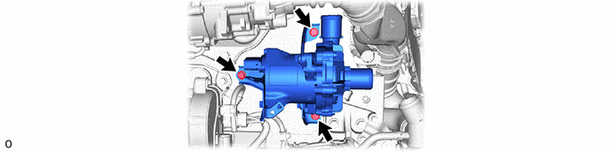
COOLING WATER PUMP REMOVAL
CAUTION / NOTICE / HINT
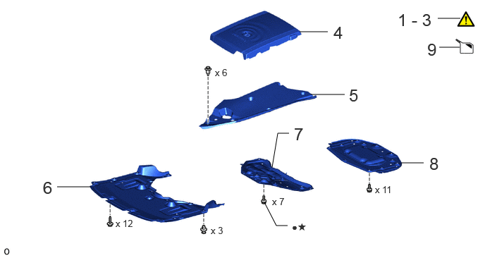
| Procedure | Part Name Code | 
|

|

|
|
|---|---|---|---|---|---|
| 1 | CAUTIONS FOR HIGH VOLTAGE SYSTEM COMPONENTS | - | ( ) |
- | - |
| 2 | CAUTIONS FOR COOLANT (TOYOTA GENUINE FC STACK COOLANT (Pre-mixed)) | - | ()
|
- | - |
| 3 | PRECAUTION | - | ()
|
- | - |
| 4 | FC STACK COVER SUB-ASSEMBLY | 1A906 | - | - | - |
| 5 | UPPER RADIATOR SUPPORT SEAL | 53292A | - | - | - |
| 6 | FRONT COMPARTMENT UNDER COVER | 51441N | - | - | - |
| 7 | FRONT LOWER SUSPENSION MEMBER PROTECTOR | 51219 | - | - | - |
| 8 | FRONT COMPARTMENT UNDER COVER ASSEMBLY | 51420A | - | - | - |
| 9 | DRAIN COOLANT (TOYOTA GENUINE FC STACK COOLANT (Pre-mixed)) | - | - | ()
|
- |
| ● | Non-reusable part | ★ | Precoated part |
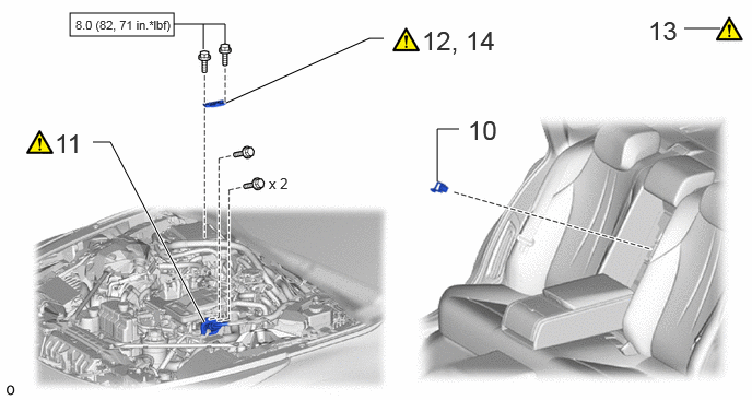
| Procedure | Part Name Code |
|
|
|
|
|---|---|---|---|---|---|
| 10 | SERVICE PLUG GRIP | G3834 | - | - | - |
| 11 | FC CONVERTER POWER OUTLET CABLE (INVERTER WITH CONVERTER ASSEMBLY) | G9200A | ()
|
- | - |
| 12 | REMOVE CONNECTOR COVER ASSEMBLY | - | ()
|
- | - |
| 13 | CHECK TERMINAL VOLTAGE | - | ()
|
- | - |
| 14 | INSTALL CONNECTOR COVER ASSEMBLY | - | ()
|
- | - |

|
N*m (kgf*cm, ft.*lbf): Specified torque | - | - |
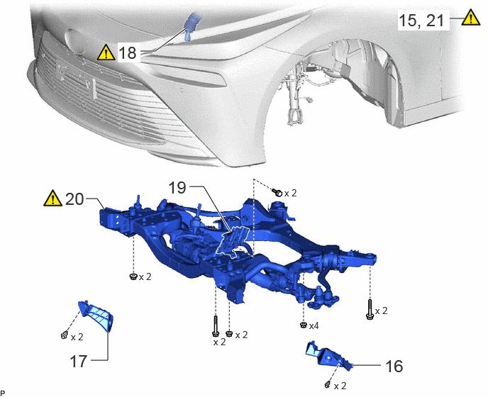
| Procedure | Part Name Code |
|
|
|
|
|---|---|---|---|---|---|
| 15 | ENGINE SUPPORT BRIDGE | - | ()
|
- | - |
| 16 | FRONT COMPARTMENT SIDE COVER LH | 51474C | - | - | - |
| 17 | FRONT COMPARTMENT SIDE COVER RH | 51473D | - | - | - |
| 18 | NO. 2 STEERING INTERMEDIATE SHAFT ASSEMBLY | 45260 | ()
|
- | - |
| 19 | WIRE HARNESS CLAMP BRACKET | - | - | - | - |
| 20 | FRONT FRAME ASSEMBLY | 51100G | ()
|
- | - |
| 21 | HOLDING BAR | - | ()
|
- | - |
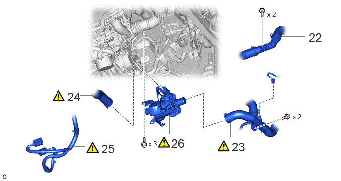
| Procedure | Part Name Code |
|
|
|
|
|---|---|---|---|---|---|
| 22 | NO. 6 FC RADIATOR PIPE | 165H6 | - | - | - |
| 23 | NO. 11 FC RADIATOR HOSE | 1657B | ()
|
- | - |
| 24 | NO. 2 FC RADIATOR HOSE | 16572F | ()
|
- | - |
| 25 | FC COOLING WATER PUMP CABLE | 16A18 | ()
|
- | - |
| 26 | FC COOLING WATER PUMP ASSEMBLY | 16A10 | ()
|
- | - |
CAUTION / NOTICE / HINT
The necessary procedures (adjustment, calibration, initialization, or registration) that must be performed after parts are removed, installed, or replaced during the FC cooling water pump assembly removal/installation are shown below.
| Replacement Part or Procedure | Necessary Procedure | Effects/Inoperative when not Performed | Link |
|---|---|---|---|
|
*: The vehicle height changes because of suspension or tire replacement. |
|||
| Disconnect cable from negative auxiliary battery terminal | Memorize steering angle neutral point | Parking assist monitor system | ()
|
| Panoramic view monitor system | ()
|
||
| Suspension, tires, etc.* | ·
Measurement of ultrasonic sensor detection angle ·
Ultrasonic sensor detection angle registration |
·
Parking support brake system ·
Advanced park |
w/ Advanced Park:
( )
w/o Advanced Park: ( )
|
| Rear television camera assembly optical axis (Back camera position setting) | Parking assist monitor system | ()
|
|
·
Parking assist ECU initialization ·
Adjust steering angle ·
Rear television camera view adjustment (for Rear camera detection system) |
Panoramic view monitor system | ()
|
|
| Perform headlight ECU sub-assembly LH initialization | Automatic headlight beam level control system | ()
|
|
| Front bumper assembly (Including removal and installation) | ·
Measurement of ultrasonic sensor detection angle ·
Ultrasonic sensor detection angle registration |
·
TOYOTA Parking assist- sensor system ·
Parking support brake system ·
Advanced park |
w/ Advanced Park:
( )
w/o Advanced Park: ( )
|
| Front television camera view adjustment | Panoramic view monitor system | ()
|
|
| Wheel alignment adjustment | Perform "Calibration" | Electronically controlled brake system malfunctions | ()
|
- HINT:
-
When the cable is disconnected/reconnected to the auxiliary battery terminal, systems temporarily stop operating. However, each system has a function that completes learning the first time the system is used.
- ·
Learning completes when vehicle is driven
Effect/Inoperative Function When Necessary Procedures are not Performed Necessary Procedures Link Lane tracing assist system Drive the vehicle straight ahead at 35 km/h (22 mph) or more for 5 seconds or more. ( )
Pre-collision system Adaptive high beam system
·Learning completes when vehicle is operated normally
Effect/Inoperative Function When Necessary Procedures are not Performed Necessary Procedures Link Air conditioning system After the ignition switch is turned to ON, the servo motor and expansion valve standard position is recognized. -
PROCEDURE

 1. CAUTIONS FOR HIGH VOLTAGE SYSTEM COMPONENTS
|
|
Click here()
|
2. CAUTIONS FOR COOLANT (TOYOTA GENUINE FC STACK COOLANT (Pre-mixed))
3. PRECAUTION
1A906
4.REMOVE FC STACK COVER SUB-ASSEMBLY
53292A
5.REMOVE UPPER RADIATOR SUPPORT SEAL
51441N
6.REMOVE FRONT COMPARTMENT UNDER COVER
51219
7.REMOVE FRONT LOWER SUSPENSION MEMBER PROTECTOR
51420A
8.REMOVE FRONT COMPARTMENT UNDER COVER ASSEMBLY
9.DRAIN COOLANT (TOYOTA GENUINE FC STACK COOLANT (Pre-mixed))
G3834
10.REMOVE SERVICE PLUG GRIP
G9200A
11.DISCONNECT FC CONVERTER POWER OUTLET CABLE (INVERTER WITH CONVERTER ASSEMBLY)
|
|
Click here()
|
12.REMOVE CONNECTOR COVER ASSEMBLY
|
|
Click here()
|
13.CHECK TERMINAL VOLTAGE
|
|
Click here()
|
14.INSTALL CONNECTOR COVER ASSEMBLY
|
|
Click here()
|
15.INSTALL ENGINE SUPPORT BRIDGE
51474C
16.REMOVE FRONT COMPARTMENT SIDE COVER LH
51473D
17.REMOVE FRONT COMPARTMENT SIDE COVER RH
Use the same procedure as for the LH side.
45260
18.DISCONNECT NO. 2 STEERING INTERMEDIATE SHAFT ASSEMBLY
|
|
Click here()
|
19.DISCONNECT WIRE HARNESS CLAMP BRACKET
51100G
20.REMOVE FRONT FRAME ASSEMBLY
|
|
Click here()
|
21.INSTALL HOLDING BAR
|
|
Click here()
|
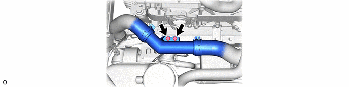
165H6
22.DISCONNECT NO. 6 FC RADIATOR PIPE
1657B
23.DISCONNECT NO. 11 FC RADIATOR HOSE
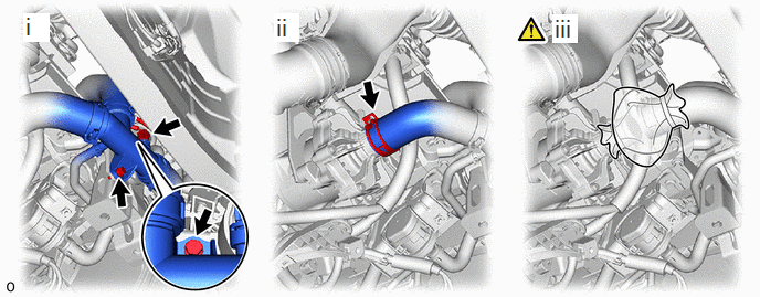
Remove the 2 bolts and disconnect the connector.
Slide the clip and disconnect the No. 11 FC radiator hose from the FC cooling water pump assembly.
To prevent contamination by foreign matter or water droplets, cover the connecting portions of the No. 11 FC radiator hose and FC cooling water pump assembly with plastic bags.
16572F
24.DISCONNECT NO. 2 FC RADIATOR HOSE
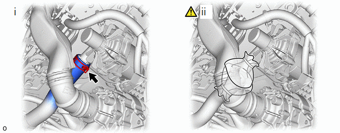
Slide the clip and disconnect the No. 2 FC radiator hose from the FC cooling water pump assembly.
To prevent contamination by foreign matter or water droplets, cover the connecting portions of the No. 2 FC radiator hose and FC cooling water pump assembly with plastic bags.
16A18
25.DISCONNECT FC COOLING WATER PUMP CABLE
|
|
|
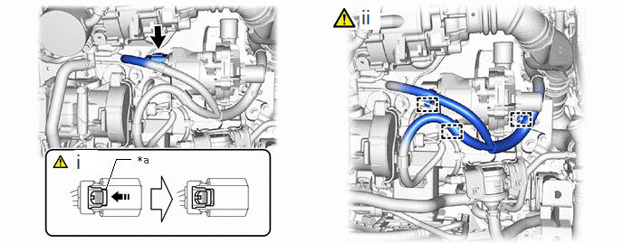
| *a | Green-colored Lock | 
|
Slide |
As shown in the illustration, pull out the green-colored lock of the connector and disconnect the FC cooling water pump cable connector.
Detach the 3 clamps and disconnect the FC cooling water pump cable.
16A10
26.REMOVE FC COOLING WATER PUMP ASSEMBLY
|
|
|