FRONT SUSPENSION FRONT SUSPENSION MEMBER REMOVAL
CAUTION / NOTICE / HINT
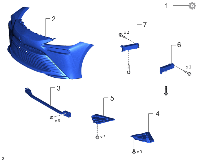
| Procedure | Part Name Code | 
|

|

|
|
|---|---|---|---|---|---|
| 1 | DISABLE BRAKE CONTROL | - | - | - | ( ) |
| 2 | FRONT BUMPER COVER | 52119A | - | - | - |
| 3 | FRONT NO. 2 BUMPER REINFORCEMENT SUB-ASSEMBLY | 52029B | - | - | - |
| 4 | RADIATOR SUPPORT EXTENSION LH | 53288B | - | - | - |
| 5 | RADIATOR SUPPORT EXTENSION RH | 53287B | - | - | - |
| 6 | REAR FRAME SIDE RAIL LH | 51116 | - | - | |
| 7 | REAR FRAME SIDE RAIL RH | 51115 | - | - | - |
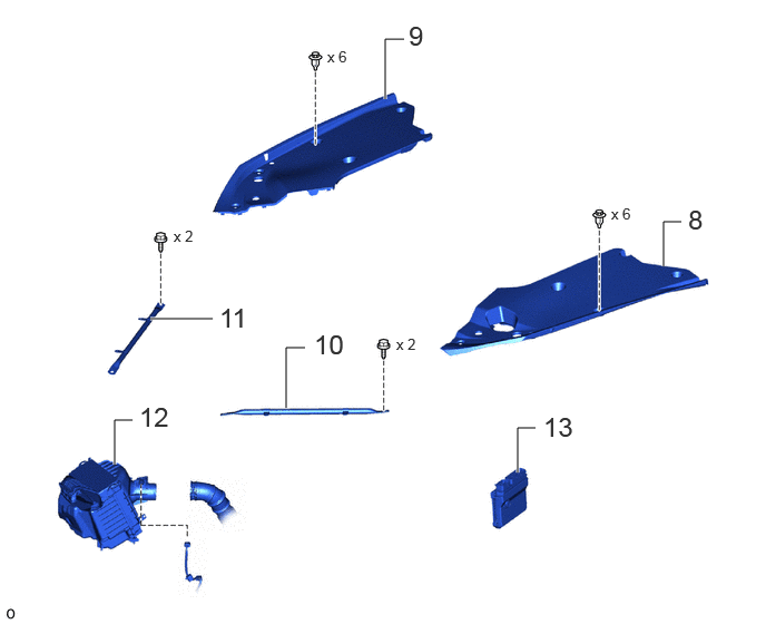
| Procedure | Part Name Code |
|
|
|
|
|---|---|---|---|---|---|
| 8 | UPPER RADIATOR SUPPORT SEAL | 53292A | - | - | - |
| 9 | RADIATOR COVER PLATE | 53291B | - | - | - |
| 10 | RADIATOR SUPPORT TO CROSS MEMBER BRACE SUB-ASSEMBLY LH | 53204E | - | - | - |
| 11 | RADIATOR SUPPORT TO CROSS MEMBER BRACE SUB-ASSEMBLY RH | 53209F | - | - | - |
| 12 | AIR CLEANER WITH ELEMENT ASSEMBLY WITH AIR CLEANER INLET | - | - | - | - |
| 13 | FC CONTROL ECU | 898A1 | - | - | - |
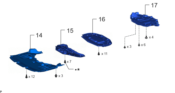
| Procedure | Part Name Code |
|
|
|
|
|---|---|---|---|---|---|
| 14 | FRONT COMPARTMENT UNDER COVER | 51441N | - | - | - |
| 15 | FRONT LOWER SUSPENSION MEMBER PROTECTOR | 51219 | - | - | - |
| 16 | FRONT COMPARTMEMT UNDER COVER ASSEMBLY | 51420A | - | - | - |
| 17 | REAR NO. 4 FLOOR BOARD SUB-ASSEMBLY | 58404B | - | - | - |
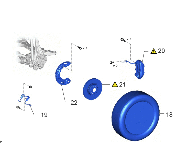
| Procedure | Part Name Code |
|
|
|
|
|---|---|---|---|---|---|
| 18 | FRONT TIRE LH | - | - | - | - |
| 19 | FRONT SKID CONTROL SENSOR WIRE LH | 89516F | - | - | - |
| 20 | DISC BRAKE CYLINDER ASSEMBLY LH | 47750 | ()
|
- | - |
| 21 | FRONT DISC LH | 43512 | ()
|
- | - |
| 22 | FRONT DISC BRAKE DUST COVER LH | 47782 | - | - | - |
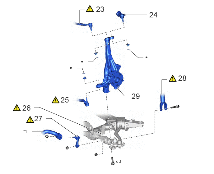
| Procedure | Part Name Code |
|
|
|
|
|---|---|---|---|---|---|
| 23 | FRONT NO. 1 UPPER SUSPENSION ARM ASSEMBLY LH | 48630D | ()
|
- | - |
| 24 | FRONT NO. 2 UPPER SUSPENSION ARM ASSEMBLY LH | 48630E | - | - | - |
| 25 | TIE ROD ASSEMBLY LH | 45470 | ()
|
- | - |
| 26 | FRONT LOWER SUSPENSION ARM ASSEMBLY LH | 48640 | ()
|
- | - |
| 27 | FRONT STABILIZER LINK ASSEMBLY LH | 48810 | ()
|
- | - |
| 28 | FRONT SHOCK ABSORBER ASSEMBLY LH | 48520 | ()
|
- | - |
| 29 | STEERING KNUCKLE LH | 43212 | - | - | - |
| *1 | FRONT STABILIZER BAR | - | - |
| ● | Non-reusable part | - | - |
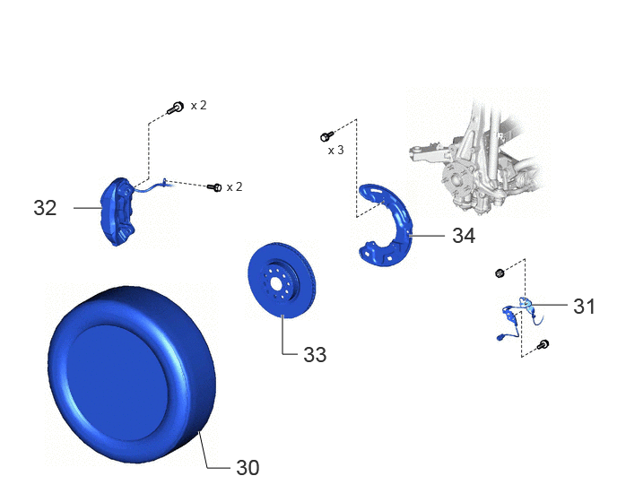
| Procedure | Part Name Code |
|
|
|
|
|---|---|---|---|---|---|
| 30 | FRONT TIRE RH | - | - | - | - |
| 31 | FRONT SKID CONTROL SENSOR WIRE RH | 89516E | - | - | - |
| 32 | DISC BRAKE CYLINDER ASSEMBLY RH | 47730 | - | - | - |
| 33 | FRONT DISC RH | 43512J | - | - | - |
| 34 | FRONT DISC BRAKE DUST COVER RH | 47781 | - | - | - |
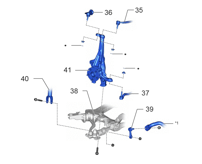
| Procedure | Part Name Code |
|
|
|
|
|---|---|---|---|---|---|
| 35 | FRONT UPPER NO. 1 SUSPENSION ARM ASSEMBLY RH | 48610H | - | - | - |
| 36 | FRONT UPPER NO. 2 SUSPENSION ARM ASSEMBLY RH | 48610J | - | - | - |
| 37 | TIE ROD ASSEMBLY RH | 45460 | - | - | - |
| 38 | FRONT LOWER SUSPENSION ARM ASSEMBLY RH | 48620 | - | - | - |
| 39 | FRONT STABILIZER LINK ASSEMBLY RH | 48820B | - | - | - |
| 40 | FRONT SHOCK ABSORBER ASSEMBLY RH | 48510 | - | - | - |
| 41 | STEERING KNUCKLE RH | 43211 | - | - | - |
| *1 | FRONT STABILIZER BAR | - | - |
| ● | Non-reusable part | - | - |
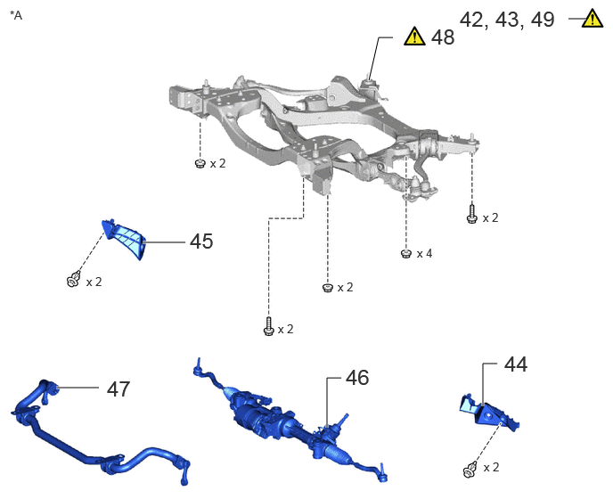
| Procedure | Part Name Code |
|
|
|
|
|---|---|---|---|---|---|
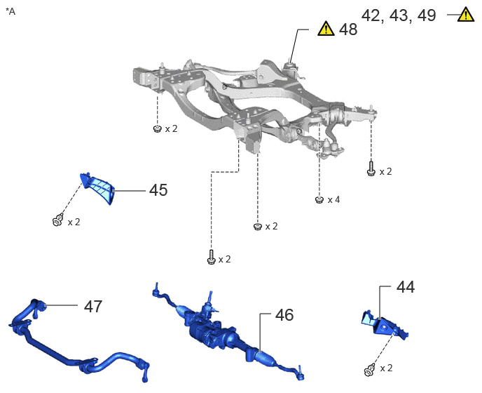
| 42 | INSTALL ENGINE HANGER | - | - | - | - |
| 43 | ENGINE SUPPORT BRIDGE | - | ()
|
- | - |
| 44 | FRONT COMPARTMENT SIDE COVER LH | 51474C | - | - | - |
| 45 | FRONT COMPARTMENT SIDE COVER RH | 51473D | - | - | - |
| 46 | RACK AND PINION POWER STEERING GEAR ASSEMBLY | 44250 | - | - | - |
| 47 | FRONT STABILIZER BAR | 48811 | - | - | - |
| 48 | FRONT FRAME ASSEMBLY | 51100G | ()
|
- | - |
| 49 | INSTALL HOLDING BAR | - | ()
|
- | - |
| *A | for LHD | - | - |
| Procedure | Part Name Code |
|
|
|
|
|---|---|---|---|---|---|
| 42 | INSTALL ENGINE HANGER | - | - | - | - |
| 43 | ENGINE SUPPORT BRIDGE | - | ()
|
- | - |
| 44 | FRONT COMPARTMENT SIDE COVER LH | 51474C | - | - | - |
| 45 | FRONT COMPARTMENT SIDE COVER RH | 51473D | - | - | - |
| 46 | RACK AND PINION POWER STEERING GEAR ASSEMBLY | 44250 | - | - | - |
| 47 | FRONT STABILIZER BAR | 48811 | - | - | - |
| 48 | FRONT FRAME ASSEMBLY | 51100G | ()
|
- | - |
| 49 | INSTALL HOLDING BAR | - | ()
|
- | - |
| *A | for RHD | - | - |
| Procedure | Part Name Code |
|
|
|
|
|---|---|---|---|---|---|
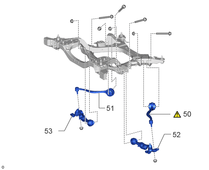
| 50 | LOWER NO. 2 SUSPENSION ARM ASSEMBLY LH | 48670A | ()
|
- | - |
| 51 | LOWER NO. 2 SUSPENSION ARM ASSEMBLY RH | 48660C | - | - | - |
| 52 | FRONT LOWER SUSPENSION ARM ASSEMBLY LH | 48640 | - | - | - |
| 53 | FRONT LOWER SUSPENSION ARM ASSEMBLY RH | 48620 | - | - | - |
CAUTION / NOTICE / HINT
The necessary procedures (adjustment, calibration, initialization, or registration) that must be performed after parts are removed, installed, or replaced during the steering knuckle removal/installation are shown below.
- Necessary Procedure After Parts Removed/Installed/Replaced:
Replacement Part or Procedure Necessary Procedures Effects/Inoperative when not Performed Link *: The vehicle height changes because of suspension or tire replacement.
Suspension, tires, etc.* ·Measurement of ultrasonic sensor detection angle
·Ultrasonic sensor detection angle registration
·Parking support brake system
·Advanced park
w/ Advanced Park:
()
w/o Advanced Park:
()
Rear television camera assembly optical axis (Back camera position setting) Parking assist monitor system ( )
·Parking assisr ECU initilization
·Adjust sttering angle
·Rear television camera view adjustment (for Rear camera detection system)
Panoramic view monitor system ( )
Perform headlight ECU sub-assembly LH initialization Automatic headlight beam level control system ( )
Rack and pinion power steering gear assembly Power steering ECU initial setting Vehicle control history (Rob) are stored ( )
Update ECU security key ( )
Disconnect cable from negative auxiliary battery terminal Memorize steering angle neutral point Parking assist monitor system ( )
Panoramic view monitor system ( )
Wheel alignment adjustment Perform "Calibration" Electronically controlled brake system malfunctions ( )
- NOTICE:
- ·
Immediately after installing the brake pads, the braking performance may be reduced. Always perform a road test in a safe place while paying attention to the surroundings.
·After replacing the front disc brake pads, the brake pedal may feel soft due to clearance between the front disc brake pads and front disc. Depress the brake pedal several times until the brake pedal feels firm.
·When removing or installing the front disc brake cylinder assembly, pushing back the disc brake piston may cause a large clearance between the brake pads and brake disc. When the brake pedal is depressed with a large clearance between the brake pads and the brake disc, DTC C13DB00, C13DC00, C13DD00, C13DE00, C140000 and/or C140A00 related to abnormal brake fluid pressure may be stored. Make sure to clear any DTCs after performing this procedure.
·While the auxiliary battery is connected, even if the ignition switch is off, the brake control system activates when the brake pedal is depressed or any door courtesy switch turns on. Therefore, when servicing the brake system components, do not operate the brake pedal or open/close the doors while the auxiliary battery is connected.
- HINT:
-
When the cable is disconnected/reconnected to the auxiliary battery terminal, systems temporarily stop operating. However, each system has a function that completes learning the first time the system is used.
- ·
Learning completes when vehicle is driven
Effect/Inoperative Function When Necessary Procedures are not Performed Necessary Procedures Link Lane tracing assist system Drive the vehicle straight ahead at 35 km/h (22 mph) or more for 5 seconds or more. ( )
Pre-collision system Adaptive high beam system
·Learning completes when vehicle is operated normally
Effect/Inoperative Function When Necessary Procedures are not Performed Necessary Procedures Link Air conditioning system After the ignition switch is turned to ON, theservo motor and expansion valve standardposition is recognized. -
·Use the same procedure for the RH and LH sides.
·The procedure listed below is for the LH side.
PROCEDURE

 1. DISABLE BRAKE CONTROL
|
|
Click here()
|
52119A
2.REMOVE FRONT BUMPER COVER
52029B
3.REMOVE FRONT NO. 2 BUMPER REINFORCEMENT SUB-ASSEMBLY
53288B
4.REMOVE RADIATOR SUPPORT EXTENSION LH
53287B
5.REMOVE RADIATOR SUPPORT EXTENSION RH
51116
6.REMOVE REAR FRAME SIDE RAIL LH
51115
7.REMOVE REAR FRAME SIDE RAIL RH
53292A
8.REMOVE UPPER RADIATOR SUPPORT SEAL
53291B
9.REMOVE RADIATOR COVER PLATE
53204E
10.REMOVE RADIATOR SUPPORT TO CROSS MEMBER BRACE SUB-ASSEMBLY LH
53209F
11.REMOVE RADIATOR SUPPORT TO CROSS MEMBER BRACE SUB-ASSEMBLY RH
12.REMOVE AIR CLEANER WITH ELEMENT ASSEMBLY WITH AIR CLEANER INLET
898A1
13.REMOVE FC CONTROL ECU (If removal and installation of a hydrogen system component is not necessary)
51441N
14.REMOVE FRONT COMPARTMENT UNDER COVER
51219
15.REMOVE FRONT LOWER SUSPENSION MEMBER PROTECTOR
51420A
16.REMOVE FRONT COMPARTMEMT UNDER COVER ASSEMBLY
58404B
17.REMOVE REAR NO. 4 FLOOR BOARD SUB-ASSEMBLY
18.REMOVE FRONT TIRE LH
89516F
19.DISCONNECT FRONT SKID CONTROL SENSOR WIRE LH
47750
20.DISCONNECT DISC BRAKE CYLINDER ASSEMBLY LH
|
|
Click here()
|
43512
21.REMOVE FRONT DISC LH
|
|
Click here()
|
47782
22.REMOVE FRONT DISC BRAKE DUST COVER LH
48630D
23.DISCONNECT FRONT UPPER NO. 1 SUSPENSION ARM ASSEMBLY LH
|
|
Click here()
|
48630E
24.DISCONNECT FRONT UPPER NO. 2 SUSPENSION ARM ASSEMBLY LH
Use the same procedure as for the front upper No. 1 suspension arm assembly LH.
45470
25.DISCONNECT TIE ROD ASSEMBLY LH
|
|
Click here()
|
48640
26.LOOSEN FRONT LOWER SUSPENSION ARM ASSEMBLY LH
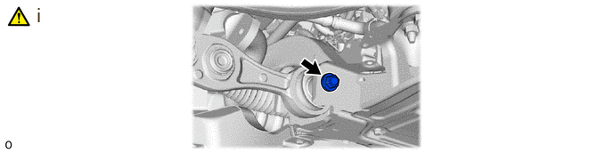
Loosen the installation bolt of the front suspension lower arm assembly LH.
- HINT:
-
Only loosen the bolt. There is no need to remove it.
48810
27.REMOVE FRONT STABILIZER LINK ASSEMBLY LH
|
|
Click here()
|
48520
28.DISCONNECT FRONT SHOCK ABSORBER ASSEMBLY LH
|
|
Click here()
|
43212
29.REMOVE STEERING KNUCKLE LH
30.REMOVE FRONT TIRE RH
Use the same procedure as for the LH side.
89516E
31.DISCONNECT FRONT SKID CONTROL SENSOR WIRE RH
Use the same procedure as for the LH side.
47730
32.DISCONNECT DISC BRAKE CYLINDER ASSEMBLY RH
Use the same procedure as for the LH side.
43512
33.REMOVE FRONT DISC RH
Use the same procedure as for the LH side.
47781
34.REMOVE FRONT DISC BRAKE DUST COVER RH
Use the same procedure as for the LH side.
48610H
35.DISCONNECT FRONT UPPER NO. 1 SUSPENSION ARM ASSEMBLY RH
Use the same procedure as for the LH side.
48610J
36.DISCONNECT FRONT UPPER NO. 2 SUSPENSION ARM ASSEMBLY RH
Use the same procedure as for the LH side.
45460
37.DISCONNECT TIE ROD ASSEMBLY RH
Use the same procedure as for the LH side.
48620
38.LOOSEN FRONT LOWER SUSPENSION ARM ASSEMBLY RH
Use the same procedure as for the LH side.
48820B
39.REMOVE FRONT STABILIZER LINK ASSEMBLY RH
Use the same procedure as for the LH side.
48510
40.DISCONNECT FRONT SHOCK ABSORBER ASSEMBLY RH
Use the same procedure as for the LH side.
43211
41.REMOVE STEERING KNUCKLE RH
Use the same procedure as for the LH side.
42.INSTALL ENGINE HANGER
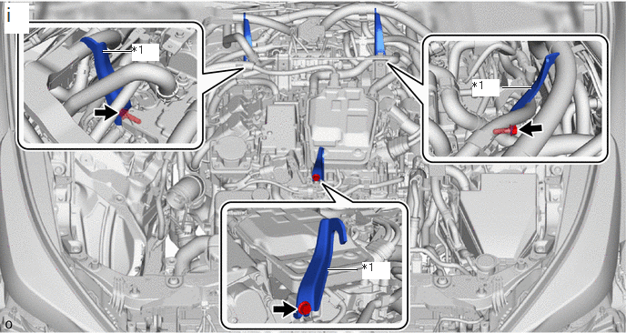
| *1 | Engine Hanger | 
|
Bolt |
Install the 3 engine hangers with the 3 bolts as shown in the illustration.
- Torque:
- 32 N*m (326 kgf*cm, 24 ft.*lbf)
| Engine Hanger | 12282-28010 |
| Bolt | 91552-K1025 |
43.INSTALL ENGINE SUPPORT BRIDGE
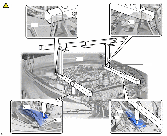
| *a | Support Shaft | *b | Front Side Member |
| *c | Front Suspension Nut | *d | 09940-10060 |
| *e | 09940-10070 | - | - |
Install SST to the vehicle body as shown in the illustration.
- SST
- 09940-10010
09940-10060
09940-10070
- CAUTION:
- ·
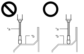 0.448,1.167 0.781,1.167 false 2.438,1.167 2.771,1.167 false 1.052,1.781 1.052,1.448 1.052,1.448 1.219,1.448 false 2.604,1.781 2.604,1.448 2.604,1.448 2.438,1.448 false 0.292,1.094 0.604,1.25 0.313,0.156 10 false *a 2.271,1.094 2.583,1.25 0.313,0.156 10 false *a 1.281,1.385 1.594,1.542 0.313,0.156 10 false *b 2.271,1.385 2.583,1.542 0.313,0.156 10 false *b
*a Support Shaft *b Front Side Member
Make sure that no oil or grease is on the front side member, and set the support shaft on the level surface of the front side member.
·The engine support bridge may fall off if any oil or grease is still on or it is installed on the unlevel surface.
- NOTICE:
- ·
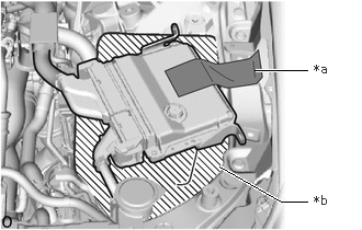 2.083,1.583 2.667,1.917 2.667,1.917 2.917,1.917 true 2.417,0.667 2.917,0.667 true 2.979,0.583 3.302,0.771 0.323,0.188 10 true *a 2.979,1.833 3.292,2.021 0.313,0.188 10 true *b
*a Tape, etc. *b Cloth, etc.
If removal and installation of a hydrogen system component is necessary:
After the FC control ECU is removed, refer to the conditions shown illustration to connect the 2 FC control ECU connectors, and move the FC control ECU to a location where it will not interfere with the engine support bridge installation.
·Prevent SST from contacting the vehicle body exterior and windshield glass.
·To prevent damage to the engine hood, place pieces of cloth between the engine hood and SST.
·Lightly shake SST by hand to make sure it is securely installed before performing work.
·Replace the short arm of SST (09940-10010) with SST (09940-10060) and SST (09910-10070).
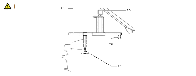
| *a | Support Shaft | *b | Sub Beam |
| *c | Front Side Member | *d | Threaded Portion |
| *e | Cloth, etc. | - | - |
Turn the threaded portion of each support shaft to adjust its height until the sub beams are parallel to the ground.
- HINT:
-
Using a piece of cloth, etc., prevent the engine support bridge from contacting the engine hood.
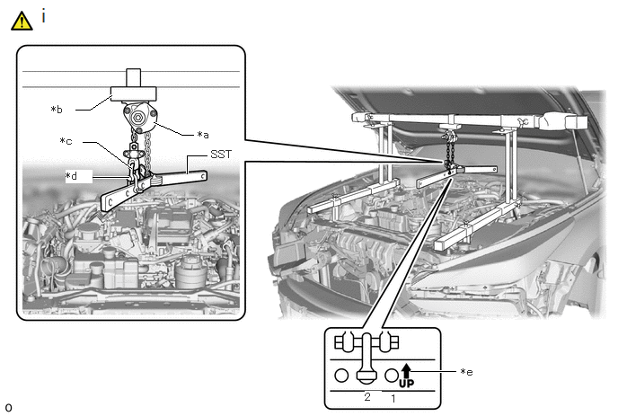
| *a | Chain Block | *b | Sling Bracket |
| *c | Fuse Shackle (09943-01010) | *d | Shackle (A) (09943-01020) |
| *e | Arrow Stamp | - | - |
Install the division bar to the chain block with the shackles.
- SST
- 09940-78010 (09941-01010, 09943-01020, 09943-01010)
- CAUTION:
- ·
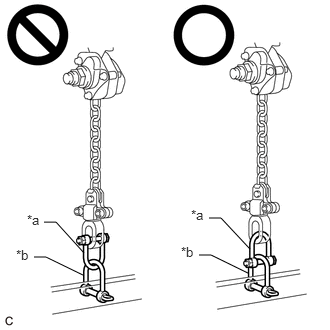 0.458,2.313 0.583,2.313 0.583,2.313 0.875,2.635 false 0.354,2.677 0.479,2.677 0.479,2.677 0.865,2.865 false 2.177,2.271 2.302,2.271 2.302,2.271 2.604,2.594 false 2.073,2.656 2.198,2.656 2.198,2.656 2.583,2.844 false 0.281,2.208 0.604,2.469 0.323,0.26 10 false *a 0.167,2.573 0.51,2.844 0.344,0.271 10 false *b 1.99,2.156 2.313,2.417 0.323,0.26 10 false *a 1.885,2.542 2.229,2.813 0.344,0.271 10 false *b
*a Fuse Shackle (09943-01010) *b Shackle (A) (09943-01020)
Make sure the fuse shackle is on the chain block side and the shackle (A) is on the division bar side as shown in the illustration so that the fuse bolt is visible and can be checked for deformation easily.
·If the fuse shackle is installed upside down, deformation of the fuse bolt will not be visible and cannot be used to tell if the load capacity of the engine support bridge has been exceeded. If the load capacity is exceeded, it may cause the engine support bridge to damage the vehicle and the FC stack assembly may fall.
·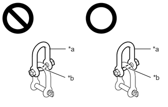 2.75,1 3.083,1 false 1.01,1 1.344,1 false 0.917,1.417 1.333,1.583 true 2.635,1.396 3.083,1.583 true 1.396,0.917 1.708,1.073 0.313,0.156 10 false *a 1.385,1.51 1.698,1.667 0.313,0.156 10 false *b 3.125,0.917 3.354,1.083 0.229,0.167 10 false *a 3.135,1.5 3.354,1.667 0.219,0.167 10 false *b
*a Fuse Shackle (09943-01010) *b Fuse Bolt
Make sure that the fuse bolt of the fuse shackle is free of damage, such as deformation or cracks. If damaged, replace the fuse shackle.
·If a deformed fuse bolt is used, it cannot be used to tell if the load capacity of the engine support bridge has been exceeded. If the load capacity is exceeded, it may cause the engine support bridge to damage the vehicle and the FC stack assembly may fall.
- NOTICE:
- ·
Make sure that the chain of the chain block is not twisted when installing the SST.
·Install the SST so that the arrow stamp faces the top of the vehicle as shown in the illustration.
- HINT:
-
Install the 2nd link from the arrow stamp on the SST to the fuse shackle and shackle (A) as shown in the illustration.
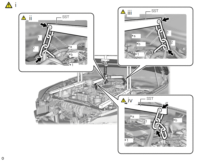
| *1 | Engine Hanger | - | - |
| *a | Shackle (A) (09943-01020) | *b | Chain (09941-01010) |
Connect the SST to the 3 engine hanger with the 3 shackle (A) and 3 chain.
for RH side:
Install the 2nd link of the chain to the engine hanger as shown in the illustration.
for LH side:
Install the 2nd link of the chain to the engine hanger as shown in the illustration.
for Front side:
Install the 1st link of the chain to the engine hanger as shown in the illustration.
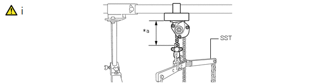
| *a | 120 mm (4.72 in.) or more | - | - |
Make sure the distance between the chain block assembly and suspension ring is 120 mm (4.72 in.) or more.
- HINT:
-
If the suspension height is less than 120 mm, adjust the links of the chain which connect the SST and engine hanger.
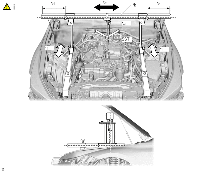
| *a | Chain Block | *b | Main Beam |
| *c | Dimension (A) | *d | Dimension (B) |
| *e | Right to Left Adjustment | *f | Front to Rear Adjustment |
Adjust the positions of the chain block assembly, support brackets and main beam so that the chain of the chain block assembly is perpendicular to the main beam and the length of the main beam on the outer side of the support bracket LH and RH is the same as shown in the illustration.
- CAUTION:
- ·
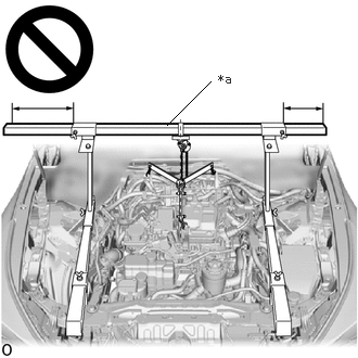 1.604,1.198 2.021,0.781 false 2.094,0.688 2.406,0.885 0.313,0.198 10 false *a
*a Main Beam
Do not perform any procedures if the length of dimension (A) and dimension (B) are not equal.
·Performing any procedure when the length of dimension (A) and dimension (B) are not equal may cause the FC stack assembly and engine support bridge to fall, possibly causing serious injury.
- NOTICE:
-
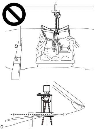
- ·
If the chain of the chain block is tilted, do not perform work.
·If the engine mount is removed with the chain of the chain block assembly tilted, the FC stack assembly may interfere with the vehicle.
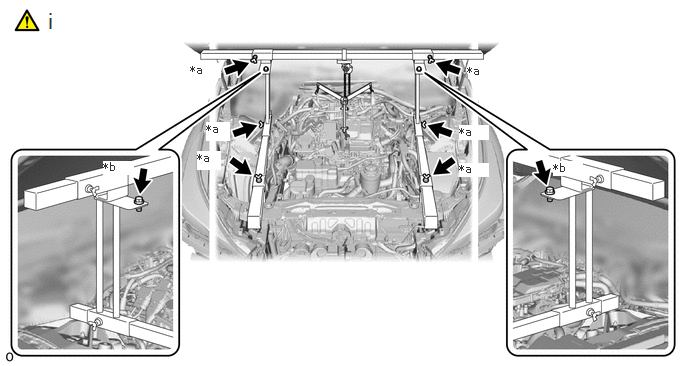
| *a | Wing Bolt | *b | Angle Fixing Bolt |
Confirm the appropriate installation state of the engine support bridge and tighten the 6 wing bolts and 2 bolts.
- Torque:
- Bolt : 30 N*m (306 kgf*cm, 22 ft.*lbf)
- CAUTION:
- ·
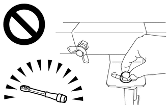
Do not perform any procedures before tightening the bolts to the specified torque.
·Performing procedures without tightening the bolts to the specified torque, may cause the engine support bridge to fall.
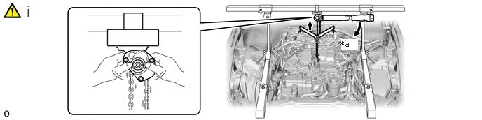
| *a | Turn | - | - |
Tighten the chain block assembly until it cannot be moved any further by hand.
- CAUTION:
-
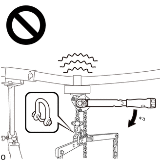 2.969,2.458 3.281,2.615 0.313,0.156 10 false *a
*a 41 N*m (418 kgf*cm, 30 ft.*lbf) or more
- ·
When suspending the FC stack assembly, do not tighten the chain block assembly more than 41 N*m (418 kgf*cm, 30 ft.*lbf).
·Tightening the chain block assembly more than 41 N*m (418 kgf*cm, 30 ft.*lbf) will cause the load capacity (400 kg (881.8 lb)) to be exceeded and may cause damage to the engine support bridge and vehicle body.
51474C
44.REMOVE FRONT COMPARTMENT SIDE COVER LH
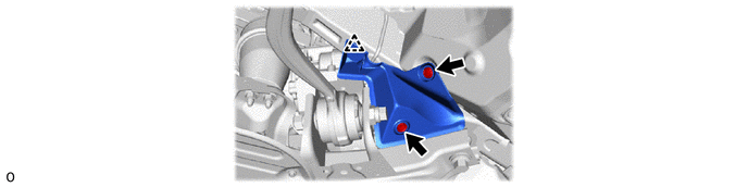
51473D
45.REMOVE FRONT COMPARTMENT SIDE COVER RH
Use the same procedure as for the LH side.
44250
46.REMOVE RACK AND PINION POWER STEERING GEAR ASSEMBLY
48811
47.REMOVE FRONT STABILIZER BAR
51100G
48.REMOVE FRONT FRAME ASSEMBLY
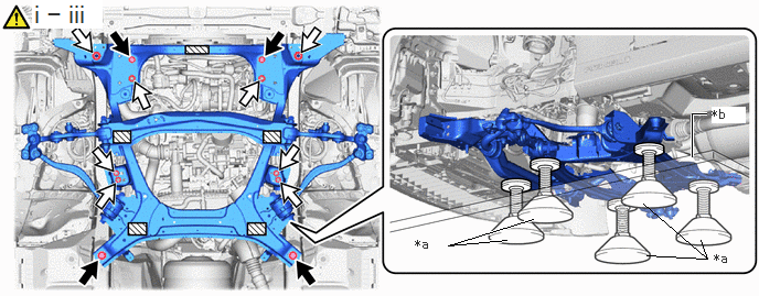
| *a | Attachment | *b | Universal Engine Lifter |
|
|
Bolt | 
|
Nut |

|
Attachment Set Position | - | - |
Set the lift attachments to the universal engine lifter to support the front frame assembly.
- CAUTION:
-
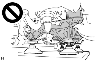
- ·
The front frame assembly is a heavy component. Make sure that it is supported securely.
·If it is not supported securely, it could fall and result in a serious accident.
- NOTICE:
-
Using the lift attachments, set the front frame assembly so that it is level.
Remove the 4 bolts and 8 nuts.
Slowly lower the front frame assembly.
- NOTICE:
-
Perform this procedure with several people supporting the front frame assembly so that it does not tilt or fall.
49.INSTALL HOLDING BAR
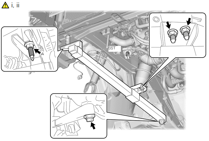
Install the SST to the right side of the vehicle.
- SST
- 09940-78020
- CAUTION:
-
Do not remove the SST (holding bar) to prevent the FC stack assembly from falling while performing work with the front frame assembly removed.
- HINT:
- ·
Use the installation nuts and bolts specialized for the vehicle.
·Make sure to tighten the nuts by hand and do not use tools.
Install the SST (holding bar) to the vehicle with the bolt and nut A.
- Torque:
- 30 N*m (306 kgf*cm, 22 ft.*lbf)
48670A
50.REMOVE LOWER NO. 2 SUSPENSION ARM ASSEMBLY LH
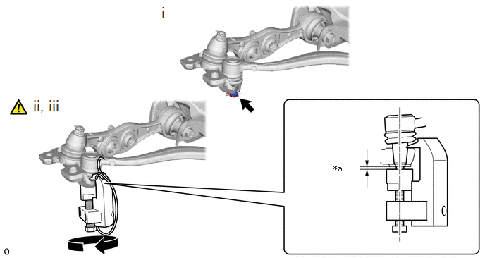
| *a | 2 mm (0.0787 in.) | - | - |
Remove the clip and nut.
Install SST (attachment) onto the lower No. 2 suspension arm assembly LH so that there is a space of approximately 2 mm (0.0787 in.) between the arm and attachment.
- SST
- 09628-50010 (09628-05010)
- NOTICE:
- ·
Be sure to install SST (attachment) in order to prevent damage to the lower No. 2 suspension arm assembly LH stud.
·As SST may become damaged, make sure the space between the arm and spacers is not 2 mm (0.0787 in.) or less.
Using SST, disconnect the lower No. 2 suspension arm assembly LH from the front lower ball joint assembly LH.
- SST
- 09628-50010 (09628-05010)
- NOTICE:
- ·
Apply molybdenum grease to the bolt threads and end of the SST bolt.
·Do not damage the dust cover of the lower No. 2 suspension arm assembly LH.
·Make sure that the bolt of SST and thelower No. 2 suspension arm assembly LH ball are in a straight line when installing SST.
·Be sure to tie the string of SST to the vehicle to prevent SST from dropping.
·Do not apply a torque of 160 N*m (1631 kgf*cm, 118 ft.*lbf) or more to SST as it may be damaged.
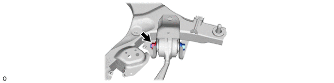
48660C
51.REMOVE LOWER NO. 2 SUSPENSION ARM ASSEMBLY RH
Perform the same procedure as for the LH side.
48640
52.REMOVE FRONT LOWER SUSPENSION ARM ASSEMBLY LH

48620
53.REMOVE FRONT LOWER SUSPENSION ARM ASSEMBLY RH
Perform the same procedure as for the LH side.