COOLING RADIATOR INSTALLATION
CAUTION / NOTICE / HINT
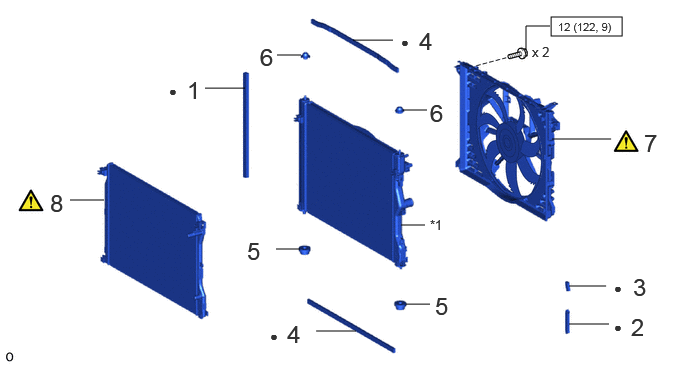
| Procedure | Part Name Code | 
|

|

|
|
|---|---|---|---|---|---|
| 1 | NO. 4 RADIATOR TO SUPPORT SEAL | 16561G | - | - | - |
| 2 | NO. 3 RADIATOR TO SUPPORT SEAL | 16561F | - | - | - |
| 3 | NO. 2 RADIATOR TO SUPPORT SEAL | 16561E | - | - | - |
| 4 | NO. 1 RADIATOR TO SUPPORT SEAL | 16561B | - | - | - |
| 5 | LOWER RADIATOR SUPPORT | - | - | - | - |
| 6 | RADIATOR SUPPORT CUSHION | 16523F | - | - | - |
| 7 | FAN WITH MOTOR ASSEMBLY | 16360B | ( ) |
- | - |
| 8 | EV RADIATOR ASSEMBLY | 16550A | ()
|
- | - |
| *1 | FC RADIATOR ASSEMBLY | - | - |

|
N*m (kgf*cm, ft.*lbf): Specified torque | ● | Non-reusable part |
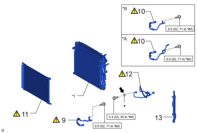
| Procedure | Part Name Code |
|
|
|
|
|---|---|---|---|---|---|
| 9 | NO. 5 FC INVERTER COOLING PIPE | G91D5 | ()
|
- | - |
| 10 | NO. 1 FC INVERTER COOLING PIPE | G91D1A | ()
|
- | - |
| 11 | COOLER CONDENSER ASSEMBLY | 884A0 | ()
|
- | - |
| 12 | NO. 1 DISCHARGE HOSE SUB-ASSEMBLY | 88703A | ()
|
- | - |
| 13 | REAR RADIATOR SIDE AIR GUIDE PLATE LH | 16697A | - | - | - |
| *A | for LHD | *B | for RHD |
| *1 | RADIATOR WITH FAN | - | - |
|
|
N*m (kgf*cm, ft.*lbf): Specified torque | ● | Non-reusable part |

|
Compressor oil ND-OIL 11 or equivalent | - | - |
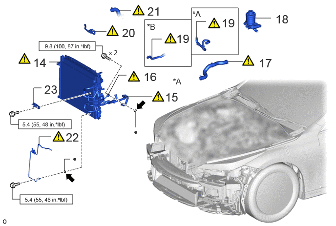
| Procedure | Part Name Code |
|
|
|
|
|---|---|---|---|---|---|
| 14 | RADIATOR WITH COOLER CONDENSER ASSEMBLY | - | ()
|
- | - |
| 15 | NO. 13 FC INVERTER COOLING HOSE | G91CD | ()
|
- | - |
| 16 | NO. 1 DISCHARGE HOSE SUB-ASSEMBLY | 88703A | ()
|
- | - |
| 17 | NO. 7 FC RADIATOR HOSE | 16577D | ()
|
- | - |
| 18 | FC COOLING WATER ION EXCHANGER ASSEMBLY | 16A40 | - | - | - |
| 19 | NO. 2 FC INVERTER COOLING HOSE | G91C2 | ()
|
- | - |
| 20 | RADIATOR TO RESERVE TANK HOSE | 16567D | ()
|
- | - |
| 21 | NO. 1 FC RADIATOR HOSE | 16571G | ()
|
- | - |
| 22 | LIQUID TUBE SUB-ASSEMBLY A | 88706A | ()
|
- | - |
| 23 | NO. 1 COOLER BRACKET | 88689E | ()
|
- | - |
| *A | for LHD | *B | for RHD |
|
|
N*m (kgf*cm, ft.*lbf): Specified torque | ● | Non-reusable part |
|
|
Compressor oil ND-OIL 11 or equivalent | - | - |
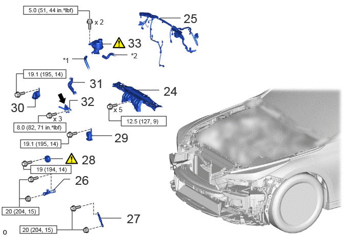
| Procedure | Part Name Code |
|
|
|
|
|---|---|---|---|---|---|
| 24 | UPPER RADIATOR SUPPORT SUB-ASSEMBLY | 53205 | - | - | - |
| 25 | FRONT COMPARTMENT MAIN WIRE | 82111C | - | - | - |
| 26 | UPPER RADIATOR SUPPORT BRACE RH | 51465 | - | - | - |
| 27 | UPPER RADIATOR SUPPORT BRACE LH | 51466 | - | - | - |
| 28 | VEHICLE APPROACHING SPEAKER ASSEMBLY | 86570 | ()
|
- | - |
| 29 | LOW PITCHED HORN ASSEMBLY | 86520 | - | - | - |
| 30 | HIGH PITCHED HORN ASSEMBLY | 86510 | - | - | - |
| 31 | HOOD LOCK CONTROL CABLE COVER | 53629A | - | - | - |
| 32 | HOOD LOCK ASSEMBLY | 53510 | ()
|
- | - |
| 33 | EV RESERVE TANK ASSEMBLY | G91H0D | ()
|
- | - |
| *1 | NO. 6 FC INVERTER COOLING HOSE | *2 | NO. 7 FC INVERTER COOLING HOSE |
|
|
N*m (kgf*cm, ft.*lbf): Specified torque |
|
MP grease |
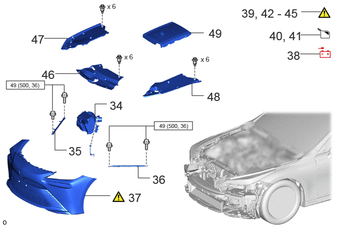
| Procedure | Part Name Code |
|
|
|
|
|---|---|---|---|---|---|
| 34 | AIR CLEANER WITH ELEMENT ASSEMBLY WITH AIR CLEANER INLET | - | - | - | - |
| 35 | RADIATOR SUPPORT TO CROSS MEMBER BRACE SUB-ASSEMBLY RH | 53209F | - | - | - |
| 36 | RADIATOR SUPPORT TO CROSS MEMBER BRACE SUB-ASSEMBLY LH | 53204E | - | - | - |
| 37 | FRONT BUMPER ASSEMBLY | - | ()
|
- | - |
| 38 | CONNECT CABLE TO NEGATIVE AUXILIARY BATTERY TERMINAL | - | - | - | - |
| 39 | CHARGE AIR CONDITIONING SYSTEM WITH REFRIGERANT | - | ()
|
- | - |
| 40 | ADD COOLANT (for Inverter) | - | - | ()
|
- |
| 41 | ADD COOLANT (TOYOTA GENUINE FC STACK COOLANT(Pre-mixed)) | - | - | ()
|
- |
| 42 | WARM UP COMPRESSOR | - | ()
|
- | - |
| 43 | INSPECT FOR REFRIGERANT LEAK | - | ()
|
- | - |
| 44 | INSPECT FOR COOLANT LEAK (for Inverter) | - | ()
|
- | - |
| 45 | INSPECT FOR COOLANT (TOYOTA GENUINE FC STACK COOLANT(Pre-mixed)) LEAK | - | ()
|
- | - |
| 46 | LOWER RADIATOR AIR DEFLECTOR | 53295 | - | - | - |
| 47 | RADIATOR COVER PLATE | 53291B | - | - | - |
| 48 | UPPER RADIATOR SUPPORT SEAL | 53292A | - | - | - |
| 49 | FC STACK COVER SUB-ASSEMBLY | 1A906 | - | - | - |
|
|
N*m (kgf*cm, ft.*lbf): Specified torque | - | - |
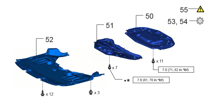
| Procedure | Part Name Code |
|
|
|
|
|---|---|---|---|---|---|
| 50 | FRONT COMPARTMEMT UNDER COVER ASSEMBLY | 51420A | - | - | - |
| 51 | FRONT LOWER SUSPENSION MEMBER PROTECTOR | 51219 | - | - | - |
| 52 | FRONT COMPARTMENT UNDER COVER | 51441N | - | - | - |
| 53 | INITIALIZATION AFTER RECONNECTING AUXILIARY BATTERY TERMINAL | - | - | - | ()
|
| 54 | PERFORM CALIBRATION | - | - | - | ()
|
| 55 | INSPECT FOR FAN WITH MOTOR ASSEMBLY | - | ()
|
- | - |
|
|
N*m (kgf*cm, ft.*lbf): Specified torque | ● | Non-reusable part |
| ★ | Precoated part | - | - |
PROCEDURE

 16561G
1.INSTALL NO. 4 RADIATOR TO SUPPORT SEAL
16561F
2.INSTALL NO. 3 RADIATOR TO SUPPORT SEAL
16561E
3.INSTALL NO. 2 RADIATOR TO SUPPORT SEAL
16561B
4.INSTALL NO. 1 RADIATOR TO SUPPORT SEAL
5.INSTALL LOWER RADIATOR SUPPORT
16523F
6.INSTALL RADIATOR SUPPORT CUSHION
16360B
7.INSTALL FAN WITH MOTOR ASSEMBLY
|
|
|
- Torque:
- 12 N*m (122 kgf*cm, 9 ft.*lbf)
16550A
8.INSTALL EV RADIATOR ASSEMBLY
|
|
()
|
G91D5
9.INSTALL NO. 5 FC INVERTER COOLING PIPE
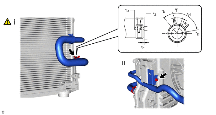
| *a | EV Radiator Assembly Rib | *b | Hose Paint Mark |
| *c | 2 to 7 mm (0.0787 to 0.2755 in.) | *d | 120° |
| *e | 20° | *f | Upper Side |
| *g | LH Side | - | - |
Connect the No. 5 FC inverter cooling pipe to the EV radiator assembly and slide the hose clip to secure it.
- NOTICE:
- ·
Align the hose and the hose clip at the locations shown in the illustration and install them.
·Make sure the No. 5 FC inverter cooling pipe is securely inserted to the stopper.
Install the No. 5 FC inverter cooling pipe to the fan with motor assembly with the bolt.
- Torque:
- 8.0 N*m (82 kgf*cm, 71 in.*lbf)
G91D1A
10.INSTALL NO. 1 FC INVERTER COOLING PIPE
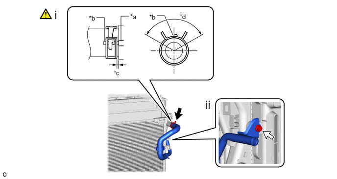
| *a | EV Radiator Assembly Rib | *b | Hose Paint Mark |
| *c | 2 to 7 mm (0.0787 to 0.2755 in.) | *d | 120° |
Connect the No. 1 FC inverter cooling pipe to the EV radiator assembly and slide the hose clip to secure it.
- NOTICE:
- ·
Align the hose and the hose clip at the locations shown in the illustration and install them.
·Make sure the No. 1 FC inverter cooling pipe is securely inserted to the stopper.
Install the No. 1 FC inverter cooling pipe to the fan with motor assembly with the bolt.
- Torque:
- 8.0 N*m (82 kgf*cm, 71 in.*lbf)
884A0
11.INSTALL COOLER CONDENSER ASSEMBLY
|
|
()
|
88703A
12.INSTALL NO. 1 DISCHARGE HOSE SUB-ASSEMBLY
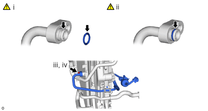
Remove the vinyl tape from the No. 1 discharge hose sub-assembly and connecting part of the cooler condenser assembly and then sufficiently apply compressor oil to a new O-ring and the fitting surface of the No. 1 discharge hose sub-assembly.
- Compressor Oil:
ND-OIL 11 or equivalent
Install the O-ring to the No. 1 discharge hose sub-assembly.
- NOTICE:
-
Keep the O-ring and O-ring fitting surface free of foreign matter.
Connect the No. 1 discharge hose sub-assembly to the cooler condenser assembly with the bolt.
- Torque:
- 5.4 N*m (55 kgf*cm, 48 in.*lbf)
Attach the clamp.
16697A
13.INSTALL REAR RADIATOR SIDE AIR GUIDE PLATE LH
14.INSTALL RADIATOR WITH COOLER CONDENSER ASSEMBLY
|
|
|
G91CD
15.CONNECT NO. 13 FC INVERTER COOLING HOSE
88703A
16.CONNECT NO. 1 DISCHARGE HOSE SUB-ASSEMBLY
|
|
()
|
16577D
17.INSTALL NO. 7 FC RADIATOR HOSE
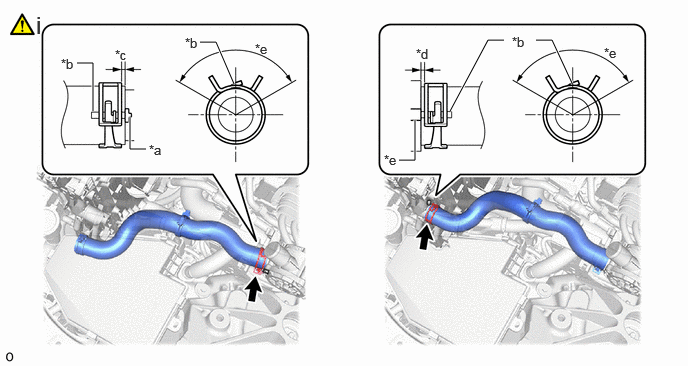
| *a | FC Cooling Water Temperature Control Valve Rib | *b | Hose Paint Mark |
| *c | 2 to 7 mm (0.0787 to 0.2755 in.) | *d | 120° |
| *e | FC Radiator Assembly Rib | - | - |
Connect the No. 7 FC radiator hose to the FC cooling water temperature control valve and FC radiator assembly and slide the 2 hose clips to secure it.
- NOTICE:
- ·
Align the hose and the hose clip at the locations shown in the illustration and install them.
·Make sure the No. 7 FC radiator hose is securely inserted to the stopper.
When connecting, if it is difficult to insert the No. 7 FC radiator hose, coat it with new coolant (Toyota genuine FC stack coolant (Pre-mixed)).
16A40
18.INSTALL FC COOLING WATER ION EXCHANGER ASSEMBLY
G91C2
19.CONNECT NO. 2 FC INVERTER COOLING HOSE
for LHD:
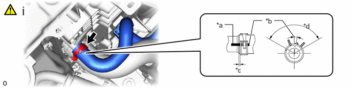
| *a | No. 1 FC Inverter Cooling Pipe Rib | *b | Hose Paint Mark |
| *c | 2 to 7 mm (0.0787 to 0.2755 in.) | *d | 120° |
Connect the No. 2 FC inverter cooling hose to the No. 1 FC inverter cooling pipe and slide the hose clip to secure it.
- NOTICE:
- ·
Align the hose and the hose clip at the locations shown in the illustration and install them.
·Make sure the No. 2 FC inverter cooling hose is securely inserted to the stopper.
Attach the 3 clamps.
for RHD:
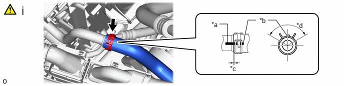
| *a | No. 1 FC Inverter Cooling Pipe Rib | *b | Hose Paint Mark |
| *c | 2 to 7 mm (0.0787 to 0.2755 in.) | *d | 120° |
Connect the No. 2 FC inverter cooling hose to the No. 1 FC inverter cooling pipe and slide the hose clip to secure it.
- NOTICE:
- ·
Align the hose and the hose clip at the locations shown in the illustration and install them.
·Make sure the No. 2 FC inverter cooling hose is securely inserted to the stopper.
16567D
20.CONNECT RADIATOR TO RESERVE TANK HOSE
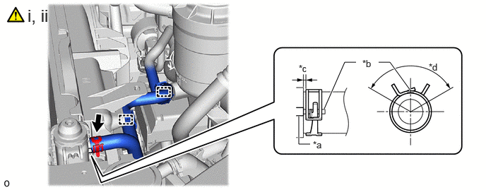
| *a | FC Radiator Assembly Rib | *b | Hose Paint Mark |
| *c | 2 to 7 mm (0.0787 to 0.2755 in.) | *d | 120° |
Connect the radiator to reserve tank hose to the FC radiator assembly and slide the hose clip to secure it.
- NOTICE:
- ·
Align the hose and the hose clip at the locations shown in the illustration and install them.
·Make sure the No. 2 FC inverter cooling hose is securely inserted to the stopper.
Attach the 2 clamps.
16571G
21.CONNECT NO. 1 FC RADIATOR HOSE
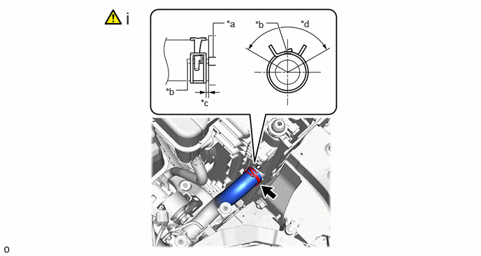
| *a | FC Radiator Assembly Rib | *b | Hose Paint Mark |
| *c | 2 to 5 mm (0.0788 to 0.1968 in.) | *d | 120° |
Connect the No. 1 FC radiator hose to the FC radiator assembly and slide the hose clip to secure it.
- NOTICE:
- ·
Align the hose and the hose clip at the locations shown in the illustration and install them.
·Make sure the No. 1 FC radiator hose is securely inserted to the stopper.
When connecting, if it is difficult to insert the No. 1 FC radiator hose, coat it with new coolant (Toyota genuine FC stack coolant (Pre-mixed)).
88706A
22.CONNECT LIQUID TUBE SUB-ASSEMBLY A
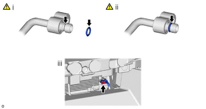
Remove the vinyl tape from the liquid tube sub-assembly A and connecting part of the cooler condenser assembly and then sufficiently apply compressor oil to a new O-ring and the fitting surface of the liquid tube sub-assembly A.
- Compressor Oil:
ND-OIL 11 or equivalent
Install the O-ring to the liquid tube sub-assembly A.
- NOTICE:
-
Keep the O-ring and O-ring fitting surface free of foreign matter.
Connect the liquid tube sub-assembly A to the cooler condenser assembly with the bolt.
- Torque:
- 5.4 N*m (55 kgf*cm, 48 in.*lbf)
88689E
23.INSTALL NO. 1 COOLER BRACKET
- Torque:
- 5.4 N*m (55 kgf*cm, 48 in.*lbf)
53205
24.INSTALL UPPER RADIATOR SUPPORT SUB-ASSEMBLY
- Torque:
- 12.5 N*m (127 kgf*cm, 9 ft.*lbf)
82111C
25.CONNECT FRONT COMPARTMENT MAIN WIRE
51465
26.INSTALL UPPER RADIATOR SUPPORT BRACE RH
- Torque:
- 20 N*m (204 kgf*cm, 15 ft.*lbf)
51466
27.INSTALL UPPER RADIATOR SUPPORT BRACE LH
- Torque:
- 20 N*m (204 kgf*cm, 15 ft.*lbf)
86570
28.INSTALL VEHICLE APPROACHING SPEAKER ASSEMBLY
|
|
()
|
86520
29.INSTALL LOW PITCHED HORN ASSEMBLY
Click hereVehicle Exterior>HORN>HORN>INSTALLATION
86510
30.INSTALL HIGH PITCHED HORN ASSEMBLY
Click hereVehicle Exterior>HORN>HORN>INSTALLATION
53629A
31.INSTALL HOOD LOCK CONTROL CABLE COVER
53510
32.INSTALL HOOD LOCK ASSEMBLY
|
|
·
for LHD: ( ·
for RHD: ( |
G91H0D
33.INSTALL EV RESERVE TANK ASSEMBLY
|
|
()
|
34.INSTALL AIR CLEANER WITH ELEMENT ASSEMBLY WITH AIR CLEANER INLET
53209F
35.INSTALL RADIATOR SUPPORT TO CROSS MEMBER BRACE SUB-ASSEMBLY RH
53204E
36.INSTALL RADIATOR SUPPORT TO CROSS MEMBER BRACE SUB-ASSEMBLY LH
37.INSTALL FRONT BUMPER ASSEMBLY
|
|
()
|
38.CONNECT CABLE TO NEGATIVE AUXILIARY BATTERY TERMINAL
39.CHARGE AIR CONDITIONING SYSTEM WITH REFRIGERANT
for HFC-134a(R134a):
Click hereVehicle Interior>HEATING / AIR CONDITIONING>REFRIGERANT (for HFC-134a(R134a))>REPLACEMENT
for HFO-1234yf(R1234yf):
Click hereVehicle Interior>HEATING / AIR CONDITIONING>REFRIGERANT (for HFO-1234yf(R1234yf))>REPLACEMENT
40.ADD COOLANT (for Inverter)
41.ADD COOLANT (TOYOTA GENUINE FC STACK COOLANT(Pre-mixed))
42.WARM UP COMPRESSOR
for HFC-134a(R134a):
Click hereVehicle Interior>HEATING / AIR CONDITIONING>REFRIGERANT (for HFC-134a(R134a))>REPLACEMENT
for HFO-1234yf(R1234yf):
Click hereVehicle Interior>HEATING / AIR CONDITIONING>REFRIGERANT (for HFO-1234yf(R1234yf))>REPLACEMENT
43.INSPECT FOR REFRIGERANT LEAK
for HFC-134a(R134a):
Click hereVehicle Interior>HEATING / AIR CONDITIONING>REFRIGERANT (for HFC-134a(R134a))>REPLACEMENT
for HFO-1234yf(R1234yf):
Click hereVehicle Interior>HEATING / AIR CONDITIONING>REFRIGERANT (for HFO-1234yf(R1234yf))>REPLACEMENT
44.INSPECT FOR COOLANT LEAK (for Inverter)
45.INSPECT FOR COOLANT (TOYOTA GENUINE FC STACK COOLANT(Pre-mixed)) LEAK
53295
46.INSTALL LOWER RADIATOR AIR DEFLECTOR
53291B
47.INSTALL RADIATOR COVER PLATE
53292A
48.INSTALL UPPER RADIATOR SUPPORT SEAL
1A906
49.INSTALL FC STACK COVER SUB-ASSEMBLY
51420A
50.INSTALL FRONT COMPARTMEMT UNDER COVER ASSEMBLY
51219
51.INSTALL FRONT LOWER SUSPENSION MEMBER PROTECTOR
51441N
52.INSTALL FRONT COMPARTMENT UNDER COVER
53. INITIALIZATION AFTER RECONNECTING AUXILIARY BATTERY TERMINAL
Click hereGeneral>SETUP>WHEN DISCONNECTING OR RECONNECTING BATTERY TERMINAL>WORK PROCEDURE
- HINT:
-
When disconnecting and reconnecting the auxiliary battery, there is an automatic learning function that completes learning when the respective system is used.
-
Click hereGeneral>SETUP>WHEN DISCONNECTING OR RECONNECTING BATTERY TERMINAL>AUTOMATIC LEARNING CHART
54.PERFORM CALIBRATION
w/ Advanced Park:
w/o Advanced Park, w/ Parking Support Brake System:
Click hereAudio / Visual / Telematics>PARK ASSIST / MONITORING>PARKING SUPPORT BRAKE SYSTEM>CALIBRATION
16360B
55.INSPECT FOR FAN WITH MOTOR ASSEMBLY