DOOR / HATCH REAR DOOR DISASSEMBLY
CAUTION / NOTICE / HINT
The necessary procedures (adjustment, calibration, initialization or registration) that must be performed after parts are removed, installed or replaced during the rear door disassembly/reassembly are shown below.
| Replaced Part or Performed Procedure | Necessary Procedure | Effect/Inoperative Function when Necessary Procedure not Performed | Link |
|---|---|---|---|
|
*: When performing learning using the GTS. Click here( |
|||
| Removal and installation of auxiliary battery terminal | Perform steering sensor zero point calibration | Lane control system | ( ) |
| Parking support brake system (for HV model)* | |||
| Pre-collision system | |||
| Memorize steering angle neutral point | Parking assist monitor system | ()
|
|
| Panoramic view monitor system (for HV model) | ()
|
||
| Reset back door close position | Power back door system (for HV model) | ()
|
|
| Power back door initialization | Power door lock control system | ()
|
|
·
Power window regulator motor assembly LH ·
Power window regulator motor assembly RH ·
Rear door window regulator sub-assembly LH ·
Rear door window regulator sub-assembly RH ·
Rear door glass sub-assembly LH ·
Rear door glass sub-assembly RH ·
Rear door glass run LH ·
Rear door glass run RH |
Initialize power window control system | ·
Auto up and down function ·
Jam protection function ·
Catch protection function ·
Remote control function ·
Wireless transmitter-linked function ·
Key-linked function ·
Key-off operation function ·
Window open warning function |
()
|
- NOTICE:
-
After the ignition switch is turned off, the navigation system requires approximately a minute to record various types of memory and settings. As a result, after turning the ignition switch off, wait a minute or more before disconnecting the cable from the negative (-) auxiliary battery terminal.
| Replaced Part or Performed Procedure | Necessary Procedure | Effect/Inoperative Function when Necessary Procedure not Performed | Link |
|---|---|---|---|
|
*: When performing learning using the GTS. Click here( |
|||
| Removal and installation of auxiliary battery terminal | Drive the vehicle until stop and start control is permitted (approximately 5 to 60 minutes) | Stop and start system | for A25A-FKS:()
for M20A-FKS:( )
|
| Perform steering sensor zero point calibration | Lane control system | ()
|
|
| Parking support brake system (for Gasoline model)* | |||
| Pre-collision system | |||
| Memorize steering angle neutral point | Parking assist monitor system | ()
|
|
| Panoramic view monitor system (for Gasoline model) | ()
|
||
| Reset back door close position | Power back door system (for Gasoline model) | ()
|
|
| Power back door initialization | Power door lock control system | ()
|
|
·
Power window regulator motor assembly LH ·
Power window regulator motor assembly RH ·
Rear door window regulator assembly LH ·
Rear door window regulator assembly RH ·
Rear door glass sub-assembly LH ·
Rear door glass sub-assembly RH ·
Rear door glass run LH ·
Rear door glass run RH ·
Rear door No. 3 glass run LH ·
Rear door No. 3 glass run RH |
Initialize power window control system | ·
Auto up and down function ·
Jam protection function ·
Catch protection function ·
Remote control function ·
Wireless transmitter-linked function ·
Key-linked function ·
Key-off operation function ·
Window open warning function |
()
|
- NOTICE:
-
After the ignition switch is turned off, the navigation system requires approximately a minute to record various types of memory and settings. As a result, after turning the ignition switch off, wait a minute or more before disconnecting the cable from the negative (-) auxiliary battery terminal.
- HINT:
- ·
Use the same procedure for RHD and LHD vehicles.
·The procedure below is for LHD vehicles.
·Use the same procedure for the RH and LH sides.
·The procedure below is for the LH side.
·When performing disassembly for the rear door, disconnect the negative (-) auxiliary battery terminal after fully opening the rear door glass.
PROCEDURE

 1. PRECAUTION
- NOTICE:
-
After turning the ignition switch off, waiting time may be required before disconnecting the cable from the negative (-) auxiliary battery terminal. Therefore, make sure to read the disconnecting the cable from the negative (-) auxiliary battery terminal notices before proceeding with work.
-
Click hereGeneral>INTRODUCTION>REPAIR INSTRUCTION>PRECAUTION
58410B
2.REMOVE DECK BOARD ASSEMBLY (for HV Model)
58416K
3.REMOVE REAR NO. 2 FLOOR BOARD (for HV Model)
65351A
4.REMOVE BATTERY HOLE COVER (for HV Model)
5.DISCONNECT CABLE FROM NEGATIVE AUXILIARY BATTERY TERMINAL
for A25A-FXS:
Click hereGeneral>MAINTENANCE>A25A-FXS AUXILIARY BATTERY>REMOVAL
for A25A-FKS:
for M20A-FKS:
for A25B-FXS:
Click hereGeneral>MAINTENANCE>A25B-FXS AUXILIARY BATTERY>REMOVAL
- CAUTION:
-
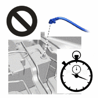
- ·
Wait at least 90 seconds after disconnecting the cable from the negative (-) auxiliary battery terminal to disable the SRS system.
·If the airbag deploys for any reason, it may cause a serious accident.
- NOTICE:
-
When disconnecting the cable, some systems need to be initialized after the cable is reconnected.
-
Click hereGeneral>INTRODUCTION>REPAIR INSTRUCTION>INITIALIZATION
69278C
6.REMOVE REAR DOOR INSIDE HANDLE BEZEL LH
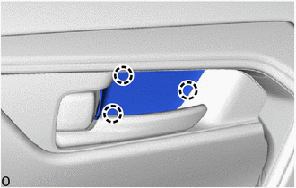
Detach the claw and remove the rear door inside handle bezel LH.
74646A
7.REMOVE DOOR ASSIST GRIP COVER LH
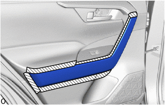

|
Protective Tape |
Apply protective tape to the rear door trim board sub-assembly LH as shown in the illustration.
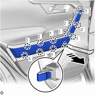

|
Remove in this Direction |
Using a moulding remover A, detach the clip.
Detach the claw in the order shown in the illustration.
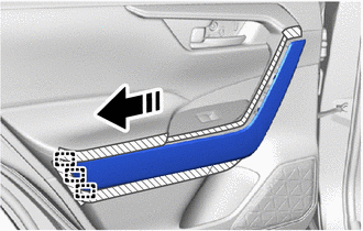
|
|
Remove in this Direction |
Detach the guide in the direction indicated by the arrow shown in the illustration and remove the door assist grip cover LH.
8.REMOVE REAR POWER WINDOW REGULATOR SWITCH ASSEMBLY WITH REAR DOOR ARMREST BASE PANEL
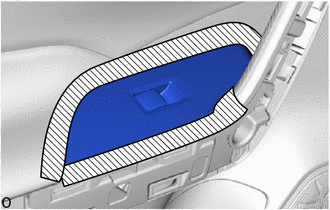
|
|
Protective Tape |
Apply protective tape around the rear power window regulator switch assembly with rear door armrest base panel.
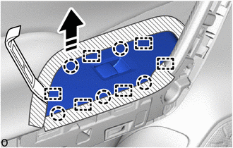
|
|
Remove in this Direction |
Using a moulding remover A, detach the guide and claw as shown in the illustration.
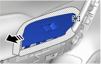
|
|
Remove in this Direction |
Detach the guide in the direction indicated by the arrow shown in the illustration and remove the rear power window regulator switch assembly with rear door armrest base panel.
w/ Seat Heater Switch:
Disconnect the 2 connectors.
w/o Seat Heater Switch:
Disconnect the connector.
84751R
9.REMOVE REAR SEAT HEATER SWITCH (w/ Seat Heater System)
84810D
10.REMOVE REAR POWER WINDOW REGULATOR SWITCH ASSEMBLY
67604
11.REMOVE REAR DOOR TRIM BOARD SUB-ASSEMBLY LH
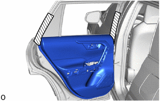
|
|
Protective Tape |
Apply protective tape to the rear door panel as shown in the illustration.
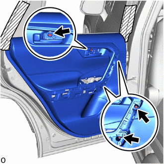
Remove the 3 screws.
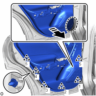

|
Place Hand Here |
|
|
Remove in this Direction |
Place your hand at the position shown in the illustration, and while pulling the rear door trim board sub-assembly LH toward you, detach the clip and disconnect the rear door trim board sub-assembly LH from the rear door panel.
- HINT:
- ·
Detach the clip in the order shown in the illustration.
·Securely detach the clip one by one.
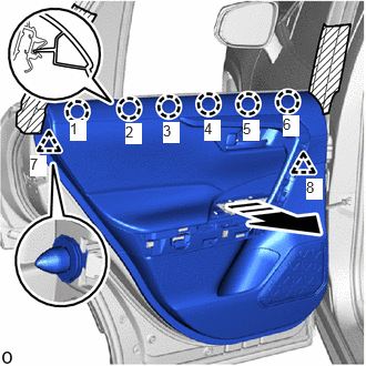
|
|
Remove in this Direction |
Pull the rear door trim board sub-assembly LH in the direction indicated by the arrow shown in the illustration to detach the claw and clip to remove the rear door trim board sub-assembly LH.
- HINT:
-
Detach the claw and clip in the order shown in the illustration.
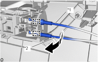
| *1 | Rear Door Inside Locking Cable Assembly |
| *2 | Rear Door Lock Remote Control Cable Assembly |
|
|
Remove in this Direction |
Detach the clamp and disconnect the rear door inside locking cable assembly and rear door lock remote control cable assembly in the direction indicated by the arrow shown in the illustration.
69206C
12.REMOVE REAR DOOR INSIDE HANDLE SUB-ASSEMBLY LH
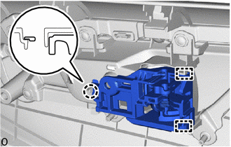
Detach the clamp and claw.
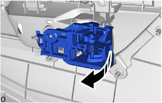
|
|
Remove in this Direction |
Remove the rear door inside handle sub-assembly LH in the direction indicated by the arrow as shown in the illustration.
68174A
13.REMOVE REAR DOOR INNER GLASS WEATHERSTRIP LH
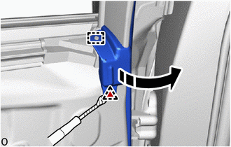
|
|
Remove in this Direction |
|
|
Protective Tape |
Using a clip remover with its tip wrapped with protective tape, detach the clip.
Detach the guide and pull back the rear door weatherstrip LH so that the rear door inner glass weatherstrip LH can be removed.
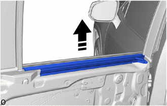
|
|
Remove in this Direction |
Remove the rear door inner glass weatherstrip LH with rear door front belt seal LH as shown in the illustration.
68197A
14.REMOVE REAR DOOR FRONT BELT SEAL LH
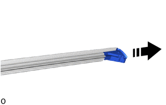
|
|
Remove in this Direction |
Remove the rear door front belt seal LH from the rear door inner glass weatherstrip LH as shown in the illustration.
68199
15.REMOVE REAR DOOR REAR BELT SEAL LH
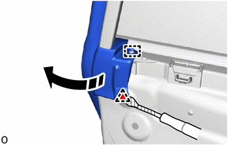
|
|
Remove in this Direction |
|
|
Protective Tape |
Using a clip remover with its tip wrapped with protective tape, detach the clip.
Detach the guide and pull back the rear door weatherstrip LH so that the rear door rear belt seal LH can be removed.
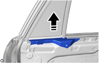
|
|
Remove in this Direction |
Remove the rear door rear belt seal LH as shown in the illustration.
86160B
16.REMOVE REAR SPEAKER ASSEMBLY
67842E
17.REMOVE REAR DOOR SERVICE HOLE COVER LH
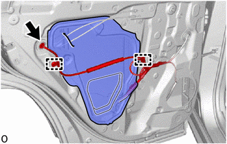
Disconnect the connector and detach the clamp.
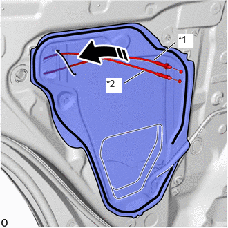
| *1 | Rear Door Lock Remote Control Cable Assembly |
| *2 | Rear Door Inside Locking Cable Assembly |
|
|
Remove in this Direction |
Pull out the rear door lock remote control cable assembly and rear door inside locking cable assembly from the rear door service hole cover LH, and then remove the rear door service hole cover LH.
- HINT:
-
Remove any remaining butyl tape from the rear door panel.
67674A
18.REMOVE REAR DOOR FRAME GARNISH LH
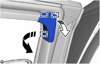
|
|
Remove in this Direction (1) |

|
Remove in this Direction (2) |
Detach the guide and remove the rear door frame garnish LH in the direction indicated by the arrows, in the order shown in the illustration.
68152C
19.DISCONNECT REAR DOOR GLASS RUN LH
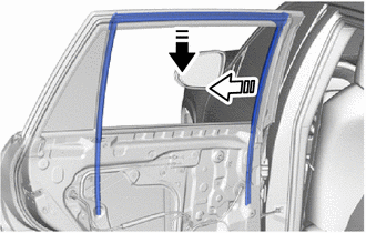
|
|
Remove in this Direction (1) |
|
|
Remove in this Direction (2) |
Disconnect the rear door glass run LH as shown in the illustration.
- HINT:
-
Leave the rear side of the rear door glass run LH on the rear door window division bar sub-assembly LH.
67408E
20.REMOVE REAR DOOR WINDOW DIVISION BAR SUB-ASSEMBLY LH
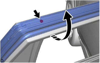
|
|
Pull back in this Direction |
Pull back part of the rear door weatherstrip LH and remove the screw as shown in the illustration.
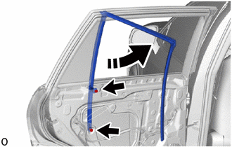
|
|
Remove in this Direction |
Remove the 2 bolts and the rear door window division bar sub-assembly LH with rear door glass run LH in the direction of the arrow indicated in the illustration.
68152C
21.REMOVE REAR DOOR GLASS RUN LH
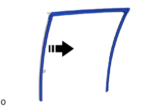
|
|
Remove in this Direction |
Remove the rear door glass run LH from the rear door window division bar sub-assembly LH.
68124C
22.REMOVE REAR DOOR QUARTER WINDOW GLASS LH
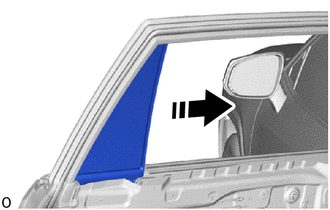
|
|
Remove in this Direction |
Remove the rear door quarter window glass LH with rear door quarter window weatherstrip LH as shown in the illustration.
68189
23.REMOVE REAR DOOR QUARTER WINDOW WEATHERSTRIP LH
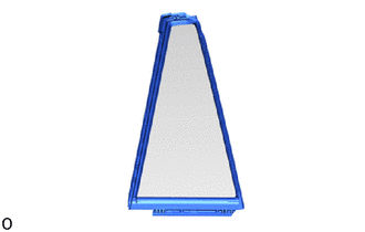
Remove the rear door quarter window weatherstrip LH from the rear door quarter window glass LH.
68104
24.REMOVE REAR DOOR GLASS SUB-ASSEMBLY LH
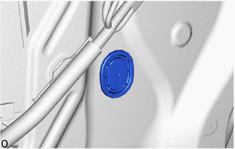
Remove the hole plug.
Connect the power window regulator switch assembly connector.
Connect the cable to the negative (-) auxiliary battery terminal.
for A25A-FXS:
Click hereGeneral>MAINTENANCE>A25A-FXS AUXILIARY BATTERY>INSTALLATION
for A25A-FKS:
for M20A-FKS:
for A25B-FXS:
Click hereGeneral>MAINTENANCE>A25B-FXS AUXILIARY BATTERY>INSTALLATION
Turn the ignition switch to ON.
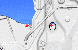
Move the rear door glass sub-assembly LH until the installation bolts can be seen.
Turn the ignition switch off.
Disconnect the cable from the negative (-) auxiliary battery terminal.
for A25A-FXS:
Click hereGeneral>MAINTENANCE>A25A-FXS AUXILIARY BATTERY>REMOVAL
for A25A-FKS:
for M20A-FKS:
for A25B-FXS:
Click hereGeneral>MAINTENANCE>A25B-FXS AUXILIARY BATTERY>REMOVAL
Disconnect the power window regulator switch assembly connector.
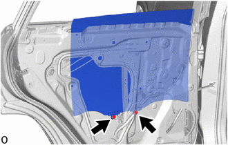
Remove the 2 bolts.
- NOTICE:
-
After the bolts are removed, do not allow the rear door glass sub-assembly to fall.
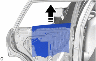
|
|
Remove in this Direction |
Remove the rear door glass sub-assembly LH as shown in the illustration.
- NOTICE:
-
Be careful not to damage the rear door glass sub-assembly LH.
69804
25.REMOVE REAR DOOR WINDOW REGULATOR SUB-ASSEMBLY LH
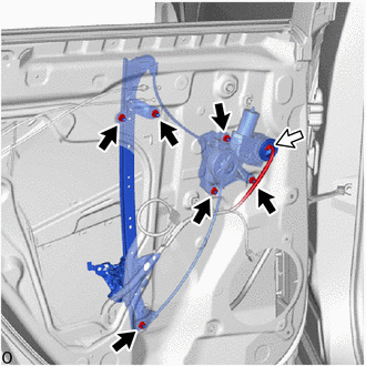

|
Nut |

|
Connector |
Disconnect the connector.
Remove the 6 nuts and the rear door window regulator sub-assembly LH.
- NOTICE:
-
Do not damage the rear door panel with the rear door window regulator sub-assembly LH.
- HINT:
-
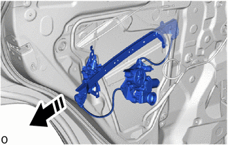 0,0 0,0 false
Remove in this Direction
-
When removing the rear door window regulator sub-assembly LH, pull it out from the service hole as shown in the illustration.
85720D
26.REMOVE POWER WINDOW REGULATOR MOTOR ASSEMBLY LH
69060A
27.REMOVE REAR DOOR LOCK WITH MOTOR ASSEMBLY LH (w/o Double Locking System)
69318D
28.REMOVE DOOR LOCK WIRING HARNESS SEAL (w/o Double Locking System)
When reusing rear door lock with motor assembly LH:
69038A
29.REMOVE REAR DOOR LOCK COVER SUB-ASSEMBLY LH (w/o Double Locking System)
69740E
30.REMOVE REAR DOOR LOCK REMOTE CONTROL CABLE ASSEMBLY (w/o Double Locking System)
69780E
31.REMOVE REAR DOOR INSIDE LOCKING CABLE ASSEMBLY (w/o Double Locking System)
69060A
32.REMOVE REAR DOOR LOCK WITH MOTOR ASSEMBLY LH (w/ Double Locking System)
69318D
33.REMOVE DOOR LOCK WIRING HARNESS SEAL (w/ Double Locking System)
When reusing rear door lock with motor assembly LH:
69740E
34.REMOVE REAR DOOR LOCK REMOTE CONTROL CABLE ASSEMBLY (w/ Double Locking System)
69780E
35.REMOVE REAR DOOR INSIDE LOCKING CABLE ASSEMBLY (w/ Double Locking System)
69240
36.REMOVE REAR DOOR OUTSIDE HANDLE ASSEMBLY LH
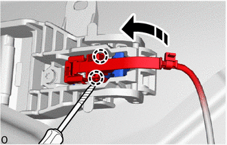
|
|
Remove in this Direction |
|
|
Protective Tape |
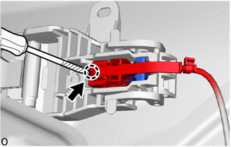
w/ Entry and Start System:
Using a screwdriver with its tip wrapped with protective tape, detach the claw and open the connector cover as shown in the illustration.
|
|
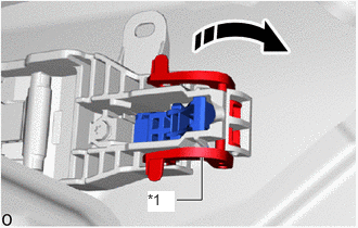
Protective Tape |
Using a screwdriver with its tip wrapped with protective tape, detach the claw to disconnect the connector and connector cover as shown in the illustration.
| *1 | Holder |
|
|
Remove in this Direction |
Detach the holder as shown in the illustration.
|
|
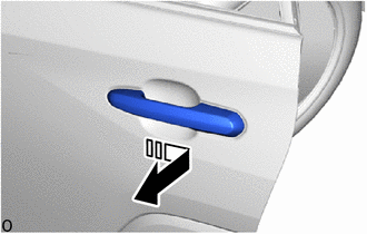
Remove in this Direction |
Remove the rear door outside handle assembly LH by sliding and pulling it in the direction indicated by the arrow in the illustration.
69227L
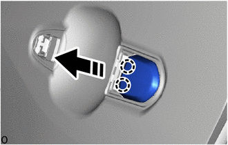
37.REMOVE REAR DOOR OUTSIDE HANDLE COVER LH
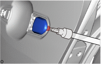
Using a T30 "TORX" socket wrench, loosen the "TORX" screw.
|
|
Remove in this Direction |
Detach the claw and remove the rear door outside handle cover LH as shown in the illustration.
69241G
38.REMOVE REAR DOOR FRONT OUTSIDE HANDLE PAD
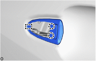
Detach the claw and guide to remove the rear door front outside handle pad.
69242G
39.REMOVE REAR DOOR REAR OUTSIDE HANDLE PAD
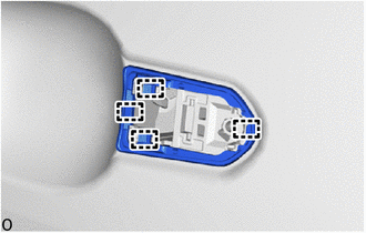
Detach the guide and remove the rear door rear outside handle pad.
69204A
40.REMOVE REAR DOOR OUTSIDE HANDLE FRAME SUB-ASSEMBLY LH
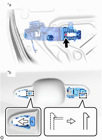
| *a | Inside |
| *b | Outside |
Using a T30 "TORX" socket wrench, loosen the "TORX"screw.
Detach the guide and remove the rear door outside handle frame sub-assembly LH.
68640A
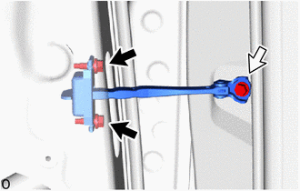
41.REMOVE REAR DOOR CHECK ASSEMBLY LH
|
|
Bolt A |
|
|
Bolt B |
Remove the 2 bolts (A), bolt (B) and rear door check assembly LH.
67872
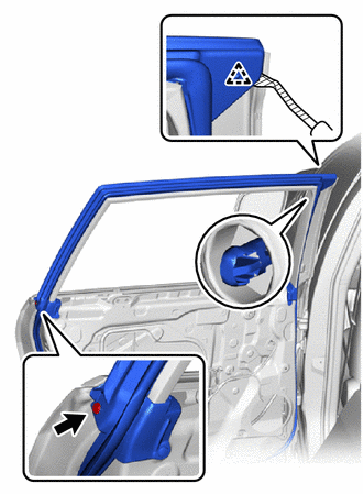
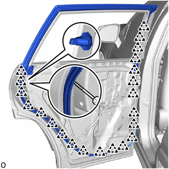
42.REMOVE REAR DOOR WEATHERSTRIP LH
|
|
Protective Tape |
Using a clip remover with its tip wrapped with protective tape, detach the clip and remove the clip.
|
|
Protective Tape |
Using a screwdriver with its tip wrapped with protective tape, detach the clip and remove the rear door weatherstrip LH.
75722A
43.REMOVE REAR DOOR BELT MOULDING LH
75762B
44.REMOVE REAR DOOR WINDOW FRAME MOULDING LH (CENTER PILLAR SIDE)
75792
45.REMOVE DOOR WINDOW FRAME MOULDING CLIP
- HINT:
-
Perform the following procedure only when replacement of a door window frame moulding clip in necessary.
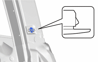
Detach the claw and remove the door window frame moulding clip.
67846A
46.REMOVE REAR DOOR FRONT OUTSIDE SEAL LH
75766B
47.REMOVE REAR DOOR WINDOW FRAME MOULDING LH (REAR PILLAR SIDE)
75764A
48.REMOVE REAR DOOR UPPER WINDOW FRAME MOULDING LH
67874C
49.REMOVE REAR DOOR NO. 5 WEATHERSTRIP LH
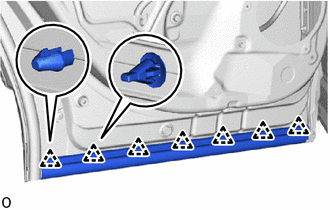
Using a screwdriver with its tip wrapped with protective tape, detach the clip and remove the rear door No. 5 weatherstrip LH.
75078
50.REMOVE REAR DOOR LOWER OUTSIDE MOULDING SUB-ASSEMBLY LH
75062
51.REMOVE OUTSIDE MOULDING SET LH (for Off Road Package)
75062
52.REMOVE OUTSIDE MOULDING SET LH (except Off Road Package)
67858B
53.REMOVE REAR DOOR PANEL PROTECTOR LH
67836H
54.REMOVE REAR DOOR LOCK CHILD PROTECTION COVER LH (w/ Child Protection Cover)
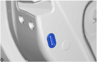
Remove the rear door lock child protection cover LH.
55.REMOVE SCREW GROMMET
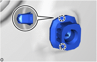
Detach the claw and remove the screw grommet.
- HINT:
-
Use the same procedure described for the other side.
67003C
56.REMOVE REAR DOOR PANEL CUSHION
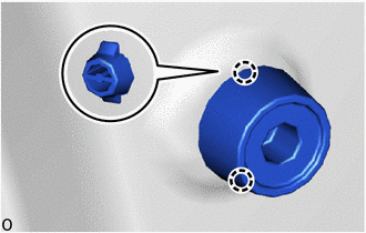
Detach the claw and remove the rear door panel cushion.
57.REMOVE HOLE PLUG
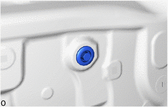
Remove the hole plug.
- HINT:
-
Use the same procedure described for the other side.
75978H
58.REMOVE REAR DOOR LOWER OUTSIDE STRIPE LH (w/ Black Out Tape)
75988E
59.REMOVE REAR DOOR OUTSIDE STRIPE LH (w/ Black Out Tape)
75954A
60.REMOVE REAR INNER BLACK OUT TAPE LH (w/ Black Out Tape)