HEATING / AIR CONDITIONING AIR CONDITIONING UNIT(for RHD) INSTALLATION
PROCEDURE

 87010
1.INSTALL AIR CONDITIONING UNIT ASSEMBLY
Install the air conditioning unit assembly.
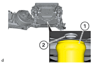
Ensure correct fit of condensate drain (2) on grommet (1).
- NOTICE:
- ·
Damage caused by water ingress into the vehicle.
Water ingress into the vehicle may result in damage to components, malfunctions and corrosion.
-Perform visual inspection after installing the air conditioning unit assembly (2).
-Only use undamaged components.
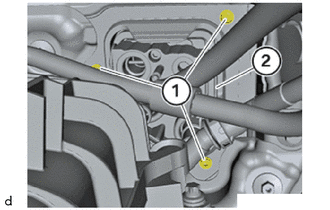
Tighten T25 screws (1) of air conditioning unit assembly (2).
- Torque:
- 2.8 N*m (29 kgf*cm, 25 in.*lbf)
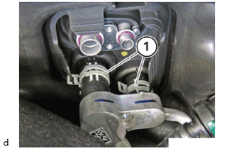
Correctly push on the heater water hoses and secure the hose clamps (1).
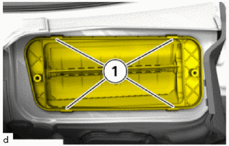
Fasten the air conditioning unit assembly with the claws (1).
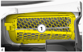
Install No. 1 air duct sub-assembly.
Tighten T25 screws (1).
- Torque:
- 2.8 N*m (29 kgf*cm, 25 in.*lbf)
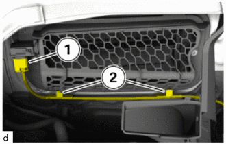
Connect the connector (1).
Engage the clamps (2).
88515
2.INSTALL COOLER EXPANSION VALVE
55305C
3.INSTALL INSTRUMENT PANEL REINFORCEMENT SUB-ASSEMBLY
Carefully insert the instrument panel reinforcement sub-assembly and connect all connectors at the same time.
- NOTICE:
-
Conduct the following operation with the assistance of a second person.
Install the air conditioning unit assembly to the instrument panel reinforcement sub-assembly first.
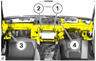
Tighten the nuts in the order shown in the illustration.
- Torque:
- 4.0 N*m (41 kgf*cm, 35 in.*lbf)
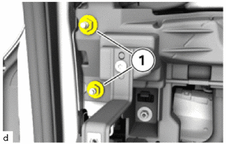
Tighten nuts (1).
- Torque:
- 21 N*m (214 kgf*cm, 15 ft.*lbf)
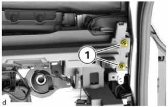
Tighten nuts (1).
- Torque:
- 21 N*m (214 kgf*cm, 15 ft.*lbf)
Using a socket wrench 16 mm, tighten bolt.
- Torque:
- 21 N*m (214 kgf*cm, 15 ft.*lbf)
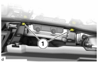
Tighten bolts (1).
- Torque:
- 21 N*m (214 kgf*cm, 15 ft.*lbf)
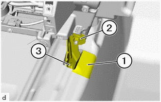
Place the carpet (1) in the marked area to the side and install the No. 1 instrument panel bracket.
Tighten bolt (3).
- Torque:
- 21 N*m (214 kgf*cm, 15 ft.*lbf)
Tighten nut (2).
- Torque:
- 21 N*m (214 kgf*cm, 15 ft.*lbf)
- HINT:
- ·
The right-hand side component is shown. The procedure on the left is identical.
·Carry out the work steps on the left and right side.
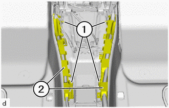
Install the cable ducts (2) and engage the claws (1).
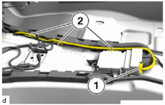
Connect the cable harness and engage the clamps (2).
Connect the connector (1).
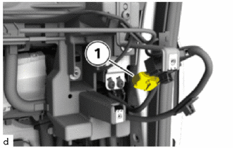
Connect the connector (1).
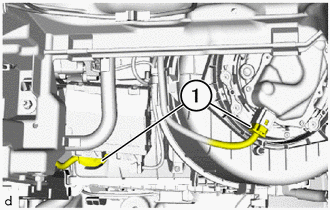
Connect the connectors (1).
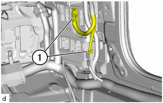
Connect the connectors (1).
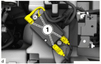
Connect the connectors (1).
45250
4.INSTALL STEERING COLUMN ASSEMBLY
83108
5.INSTALL METER MIRROR SUB-ASSEMBLY
55468C
6.INSTALL NO. 1 INSTRUMENT CLUSTER FINISH PANEL SEAL
7.INSTALL RADIO RECEIVER ASSEMBLY (w/o Navigation System)
8.INSTALL RADIO RECEIVER ASSEMBLY (w/ Navigation System)
87050C
9.INSTALL NO. 1 AIR CONDITIONING RADIATOR DAMPER SERVO SUB-ASSEMBLY (M21b)
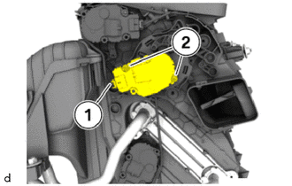
Install the No. 1 air conditioning radiator damper servo sub-assembly (M21b).
Tighten T20 screws (2).
- Torque:
- 1.2 N*m (12 kgf*cm, 11 in.*lbf)
Connect the connector (1).
10.INSTALL INSTRUMENT PANEL SAFETY PAD ASSEMBLY
87050C
11.INSTALL NO. 1 AIR CONDITIONING RADIATOR DAMPER SERVO SUB-ASSEMBLY (M16)
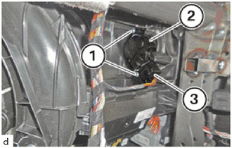
Install the No. 1 air conditioning radiator damper servo sub-assembly (M16) (2).
Tighten T20 screws (1).
- Torque:
- 1.2 N*m (12 kgf*cm, 11 in.*lbf)
Connect the connector (3).
55550
12.INSTALL GLOVE COMPARTMENT DOOR ASSEMBLY
55011A
13.INSTALL NO. 1 INSTRUMENT PANEL GARNISH SUB-ASSEMBLY
87050C
14.INSTALL NO. 1 AIR CONDITIONING RADIATOR DAMPER SERVO SUB-ASSEMBLY (M61)
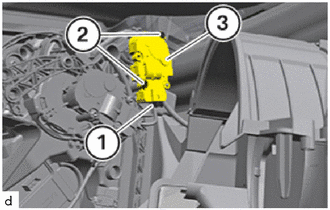
Install the No. 1 air conditioning radiator damper servo sub-assembly (M61) (3).
Tighten T20 screws (2).
- Torque:
- 1.2 N*m (12 kgf*cm, 11 in.*lbf)
Connect the connector (1).
87050C
15.INSTALL NO. 1 AIR CONDITIONING RADIATOR DAMPER SERVO SUB-ASSEMBLY (M7a)
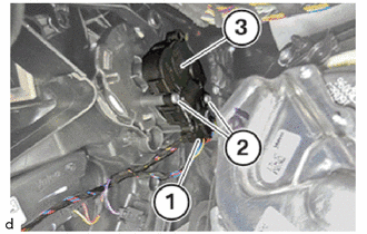
Install the No. 1 air conditioning radiator damper servo sub-assembly (M7a) (3).
Tighten T20 screws (2).
- Torque:
- 1.2 N*m (12 kgf*cm, 11 in.*lbf)
Connect the connector (1).
87050C
16.INSTALL NO. 1 AIR CONDITIONING RADIATOR DAMPER SERVO SUB-ASSEMBLY (M69)
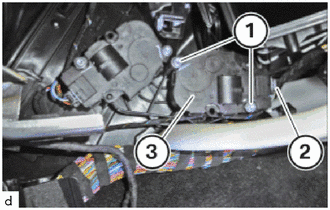
Install the No. 1 air conditioning radiator damper servo sub-assembly (M69) (3).
Tighten T20 screws (1).
- Torque:
- 1.2 N*m (12 kgf*cm, 11 in.*lbf)
Connect the connector (2).
87050C
17.INSTALL NO. 1 AIR CONDITIONING RADIATOR DAMPER SERVO SUB-ASSEMBLY (M23a)
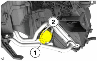
Install the No. 1 air conditioning radiator damper servo sub-assembly (M23a).
Tighten T20 screws (2).
- Torque:
- 1.2 N*m (12 kgf*cm, 11 in.*lbf)
Connect the connector (1).
87050C
18.INSTALL NO. 1 AIR CONDITIONING RADIATOR DAMPER SERVO SUB-ASSEMBLY (M83a)
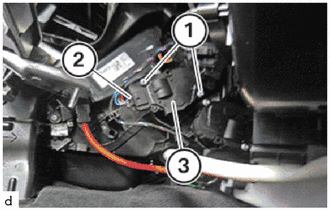
Install the No. 1 air conditioning radiator damper servo sub-assembly (M83a) (3).
Tighten T20 screws (1).
- Torque:
- 1.2 N*m (12 kgf*cm, 11 in.*lbf)
Connect the connector (2).
87103B
19.INSTALL BLOWER WITH FAN MOTOR SUB-ASSEMBLY
87211
20.INSTALL NO. 1 AIR DUCT
Install No. 1 air duct.
Tighten screw.
- Torque:
- 2.8 N*m (29 kgf*cm, 25 in.*lbf)
87211A
21.INSTALL NO. 2 AIR DUCT
Install No. 2 air duct.
Tighten screw.
- Torque:
- 2.8 N*m (29 kgf*cm, 25 in.*lbf)
73900
22.INSTALL LOWER NO. 1 INSTRUMENT PANEL AIRBAG ASSEMBLY
- HINT:
-
Use the same procedure as for LHD.
-
Click hereVehicle Interior>SUPPLEMENTAL RESTRAINT SYSTEMS>KNEE AIRBAG ASSEMBLY (for Driver Side)>INSTALLATION
55606
23.INSTALL NO. 1 INSTRUMENT PANEL UNDER COVER SUB-ASSEMBLY
55607
24.INSTALL NO. 2 INSTRUMENT PANEL UNDER COVER SUB-ASSEMBLY
88710
25.CONNECT AIR CONDITIONER TUBE ASSEMBLY
16470
26.INSTALL RADIATOR RESERVE TANK ASSEMBLY
27.INSTALL ENGINE ROOM ECM BOX
for B48:
Click hereEngine / Hybrid System>B48 (ENGINE MECHANICAL)>ENGINE ASSEMBLY>INSTALLATION
for B58:
Click hereEngine / Hybrid System>B58 (ENGINE MECHANICAL)>ENGINE ASSEMBLY>INSTALLATION
28.INSTALL NO. 1 INTEGRATION RELAY
29.INSTALL ECM (for B48)
30.INSTALL ECM (for B58)
53681
31.INSTALL UPPER CENTER FRONT SUSPENSION BRACE
32.ADD ENGINE COOLANT (for B48)
33.ADD ENGINE COOLANT (for B58)
34. CHARGE AIR CONDITIONING SYSTEM WITH REFRIGERANT
35. CHECK WIPER AND WASHER SYSTEM