B58 INTAKE / EXHAUST TURBOCHARGER REMOVAL
CAUTION / NOTICE / HINT
- CAUTION:
- ·
Hot surfaces.
Risk of burning!
-Perform all work only on components that have cooled down.
- NOTICE:
- ·
Electrostatic discharge.
Damage to or destruction of electrical components.
-Only touch the housings of electrical components. Do not touch pins or multi-pin connectors directly.
-For additional information see:
Click hereGeneral>INTRODUCTION>REPAIR INSTRUCTION>PRECAUTION
·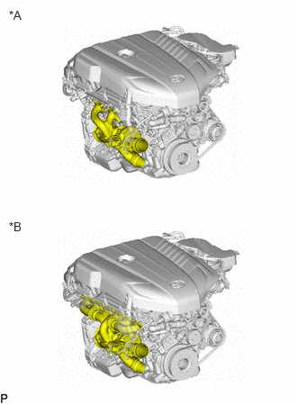 0.104,0.094 0.417,0.292 0.313,0.198 10 false *A 0.104,2.542 0.417,2.74 0.313,0.198 10 false *B
*A for 2 Port Type *B for 6 Port Type
Check the shape of the Turbo Charger SUB-ASSY before doing removal/installation work.
- HINT:
- ·
Prior to replacing the turbocharger sub-assembly: Observe the notes on troubleshooting on the turbocharger sub-assembly.
Click hereEngine / Hybrid System>B58 (INTAKE / EXHAUST)>EXHAUST SYSTEM>INSPECTION
·For turbocharger sub-assembly damage: Check the pressure pipes, intercooler and intake manifold for foreign matter, damage and correct functionality.
·If the outlet turbo oil pipe is exchanged, then the connecting pipe to the oil pan sub-assembly must always be cleaned, as the connecting pipe can coke.
PROCEDURE

 1.DISCONNECT CABLE FROM NEGATIVE BATTERY TERMINAL
Click hereGeneral>MAINTENANCE>B58 BATTERY>REMOVAL
2.REMOVE STEERING LINK ASSEMBLY
3.REMOVE EXHAUST PIPE ASSEMBLY
17882
4.REMOVE NO. 2 AIR CLEANER HOSE
12261
5.REMOVE VENTILATION HOSE
17274
6.REMOVE COMPRESSOR INLET ELBOW
7.DRAIN ENGINE COOLANT (for High-Temperature)
25051
8.REMOVE EXHAUST MANIFOLD CONVERTER SUB-ASSEMBLY
15474
9.REMOVE OUTLET TURBO OIL PIPE
17167
10.REMOVE NO. 1 EXHAUST MANIFOLD HEAT INSULATOR (for 6 Port Type)
16028
11.DISCONNECT NO. 2 TURBO WATER PIPE SUB-ASSEMBLY (for 2 Port Type)
- CAUTION:
- ·
Hot fluids.
Risk of scalding!
-Conduct all work in the vehicle wearing appropriate personal protective equipment only.
- HINT:
-
Collect and dispose of emerging fluids. Observe country specific waste disposal regulations.
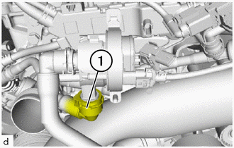
Unlock and disconnect the coolant hose (1).
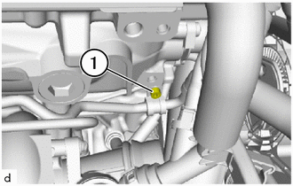
Unscrew the T30 bolt (1) on the holder of the No. 2 turbo water pipe sub-assembly.
16028
12.DISCONNECT NO. 2 TURBO WATER PIPE SUB-ASSEMBLY (for 6 Port Type)
- CAUTION:
- ·
Hot fluids.
Risk of scalding!
-Conduct all work in the vehicle wearing appropriate personal protective equipment only.
- HINT:
-
Collect and dispose of emerging fluids. Observe country specific waste disposal regulations.
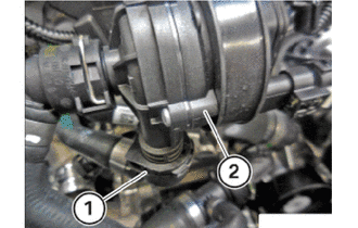
Unlock and release coolant hose (1) on water pump assembly (2) for the turbocharger sub-assembly.
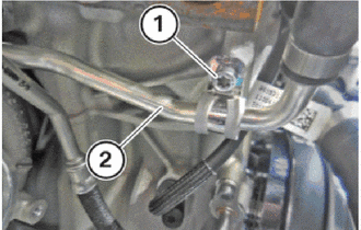
Unscrew screw (1) on the No. 2 turbo water pipe sub-assembly (2).
15407
13.DISCONNECT INLET TURBO OIL PIPE SUB-ASSEMBLY (for 2 Port Type)
- CAUTION:
- ·
Hot fluids.
Risk of scalding!
-Conduct all work in the vehicle wearing appropriate personal protective equipment only.
- HINT:
- ·
Have a rag ready and catch any engine oil that may emerge.
·Make sure no engine oil runs onto fan and generator v belt.
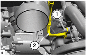
Loosen the T30 bolt (1).
Remove the inlet turbo oil pipe sub-assembly (2).
15407
14.DISCONNECT INLET TURBO OIL PIPE SUB-ASSEMBLY (for 6 Port Type)
- CAUTION:
- ·
Hot fluids.
Risk of scalding!
-Conduct all work in the vehicle wearing appropriate personal protective equipment only.
- HINT:
- ·
Have a rag ready and catch any engine oil that may emerge.
·Make sure no engine oil runs onto fan and generator v belt.
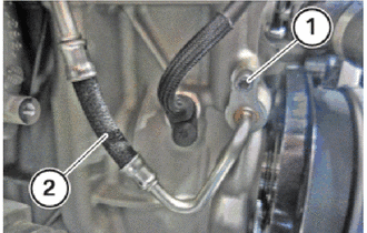
Loosen the screw (1).
Remove the inlet turbo oil pipe sub-assembly (2).
17201
15.REMOVE TURBOCHARGER SUB-ASSEMBLY (for 2 Port Type)
- CAUTION:
- ·
Hot surfaces.
Risk of burning!
-Perform all work only on components that have cooled down.
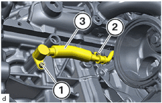
Loosen the T30 bolts (1) and (2).
Remove No. 1 turbo water pipe sub-assembly (3) from the cylinder block sub-assembly.
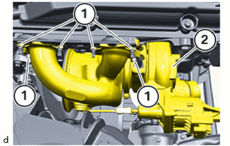
Unscrew the nuts (1) from the turbocharger sub-assembly (2).
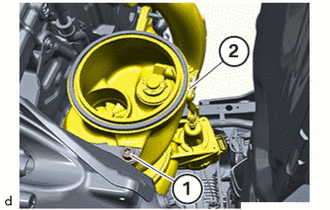
Unscrew the T40 bolt (1) from the turbocharger sub-assembly (2).
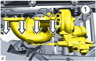
Remove the turbocharger sub-assembly (1) in the direction of the arrow.
- CAUTION:
- ·
Heavy component.
·Heavy components can lead to injury or damage.
-Remove and install heavy components with the aid of another person/other persons.
17201
16.REMOVE TURBOCHARGER SUB-ASSEMBLY (for 6 Port Type)
- CAUTION:
- ·
Hot surfaces.
Risk of burning!
-Perform all work only on components that have cooled down.
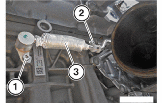
Loosen the screws (1) and (2).
Remove No. 1 turbo water pipe sub-assembly (3) from the cylinder block sub-assembly.
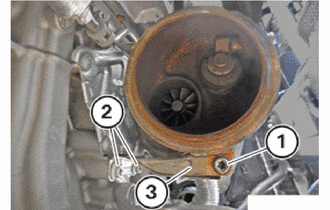
Loosen screws (1) and (2).
remove the turbocharger stay (3).
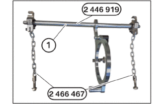
Have the set of special tools 2 446 919 and the special tool 2 446 467 ready.
- SST
- 09290-WA010 09290-WA020
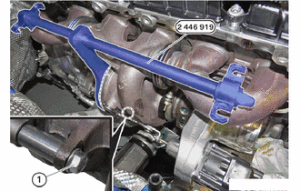
Install the special tool 2 446 919 on the turbocharger sub-assembly and secure it with the bolt (1).
- SST
- 09290-WA010
Make sure that the special tool 2 446 919 is flush with the turbocharger sub-assembly in the marked area.
- SST
- 09290-WA010
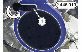
Fix the special tool 2 446 919 by turning the clamping lever (1) in the direction of the arrow.
- HINT:
-
The clamping lever that is shown in the graphic is already in its end position.
- SST
- 09290-WA010
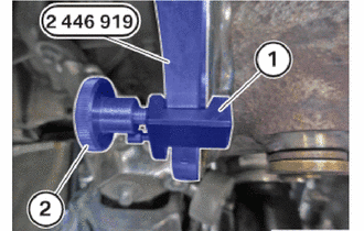
Position the holder (1) and fasten it with the bolt (2).
- HINT:
-
The holder is used for the final mounting of the special tool 2 446 919.
- SST
- 09290-WA010
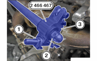
Tighten the nut (1) and (2) hand-tight.
Ensure that the special tool 2 466 467 rests correctly on the turbocharger sub-assembly (3).
- SST
- 09290-WA020
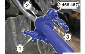
Tighten the nut (1) and (2) hand-tight.
Ensure that the special tool 2 466 467 rests correctly on the turbocharger sub-assembly (3).
- SST
- 09290-WA020
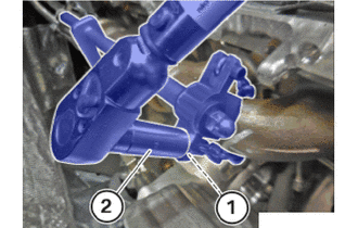
Tighten the nut (1) using commercially available tools (2).
- Torque:
- 5.0 N*m (51 kgf*cm, 44 in.*lbf)
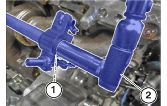
Tighten the nut (1) using commercially available tools (2).
- Torque:
- 5.0 N*m (51 kgf*cm, 44 in.*lbf)
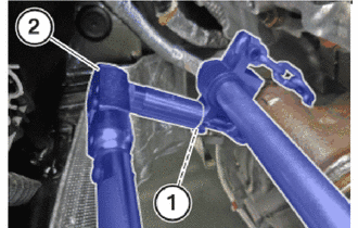
Tighten the nut (1) using commercially available tools (2).
- Torque:
- 5.0 N*m (51 kgf*cm, 44 in.*lbf)
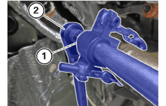
Tighten the nut (1) using commercially available tools (2).
- Torque:
- 5.0 N*m (51 kgf*cm, 44 in.*lbf)
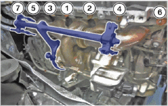
Unscrew the nuts in sequence (7) to (1).
- HINT:
-
Turbocharger sub-assembly is not bolted to the underside, but clamped instead. When removing or replacing the turbocharger sub-assembly, the clamping strip remains screwed on.
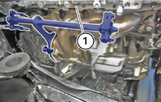
Remove the slide rail (1).
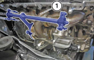
Remove the turbocharger sub-assembly (1).
- CAUTION:
- ·
Heavy component.
·Heavy components can lead to injury or damage.
-Remove and install heavy components with the aid of another person/other persons.
Thermal compensating elements of the turbocharger sub-assembly (1) or exhaust manifold should not be bent or deformed.
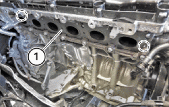
Remove exhaust manifold to head gaskets (1) in the marked area.
17.REMOVE NO.2 HEAT INSULATOR (for 6 Port Type)
- HINT:
-
Perform this procedure only when replacement of the turbocharger sub-assembly is necessary.
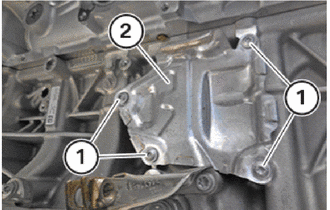
Loosen screws (1).
Remove the No.2 heat insulator (2).
16028
18.REMOVE NO. 2 TURBO WATER PIPE SUB-ASSEMBLY (for 2 Port Type)
- HINT:
-
Perform this procedure only when replacement of the turbocharger sub-assembly is necessary.
Click hereEngine / Hybrid System>B58 (INTAKE / EXHAUST)>TURBO WATER PIPE (for Outlet Side)>REMOVAL
16028
19.REMOVE NO. 2 TURBO WATER PIPE SUB-ASSEMBLY (for 6 Port Type)
- HINT:
-
Perform this procedure only when replacement of the turbocharger sub-assembly is necessary.
Click hereEngine / Hybrid System>B58 (INTAKE / EXHAUST)>TURBO WATER PIPE (for Outlet Side)>REMOVAL
15407
20.REMOVE INLET TURBO OIL PIPE SUB-ASSEMBLY (for 2 Port Type)
- HINT:
-
Perform this procedure only when replacement of the turbocharger sub-assembly is necessary.
Click hereEngine / Hybrid System>B58 (INTAKE / EXHAUST)>INLET TURBO OIL PIPE>REMOVAL
15407
21.REMOVE INLET TURBO OIL PIPE SUB-ASSEMBLY (for 6 Port Type)
- HINT:
-
Perform this procedure only when replacement of the turbocharger sub-assembly is necessary.
Click hereEngine / Hybrid System>B58 (INTAKE / EXHAUST)>INLET TURBO OIL PIPE>REMOVAL
16027
22.REMOVE NO. 1 TURBO WATER PIPE SUB-ASSEMBLY (for 2 Port Type)
- HINT:
-
Perform this procedure only when replacement of the turbocharger sub-assembly is necessary.
Click hereEngine / Hybrid System>B58 (INTAKE / EXHAUST)>TURBO WATER PIPE (for Inlet Side)>REMOVAL
16027
23.REMOVE NO. 1 TURBO WATER PIPE SUB-ASSEMBLY (for 6 Port Type)
- HINT:
-
Perform this procedure only when replacement of the turbocharger sub-assembly is necessary.
Click hereEngine / Hybrid System>B58 (INTAKE / EXHAUST)>TURBO WATER PIPE (for Inlet Side)>REMOVAL