2NZ-FE ENGINE MECHANICAL CYLINDER HEAD GASKET INSTALLATION
PROCEDURE

 11101A
1.INSPECT CYLINDER HEAD SET BOLT
11115
2.INSTALL CYLINDER HEAD GASKET
Clean and degrease the lower surface of the cylinder head sub-assembly and upper surface of the cylinder block sub-assembly.
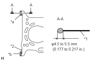
| *1 | Cylinder Head Gasket |
| *2 | No. 1 Chain Vibration Damper |
| *a | Apply enough seal packing so that it will spread to the inner side |
| *b | Apply enough seal packing so that it will spread onto the No. 1 Chain Vibration Damper |

|
Seal Packing Black |
Apply seal packing to a new cylinder head gasket in the locations shown in the illustration.
- Seal packing:
Toyota Genuine Seal Packing Black, Three Bond 1207B or equivalent
- NOTICE:
-
Install the cylinder head sub-assembly within 3 minutes and tighten the cylinder head set bolts within 15 minutes of applying seal packing.
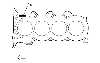
| *a | Lot No. |

|
Engine Front |
Place the cylinder head gasket on the cylinder block sub-assembly with the Lot No. stamp facing upward.
- NOTICE:
- ·
Be sure to place the cylinder head gasket in the correct direction.
·Place the cylinder head sub-assembly on the cylinder block sub-assembly gently in order not to damage the cylinder head gasket.
·After installing the cylinder head sub-assembly, wipe off any excess seal packing that seeped out.
11101
3.INSTALL CYLINDER HEAD SUB-ASSEMBLY
- HINT:
-
The cylinder head set bolts are tightened in 2 successive steps.
Apply a light coat of engine oil to the threads of the 10 cylinder head set bolts.
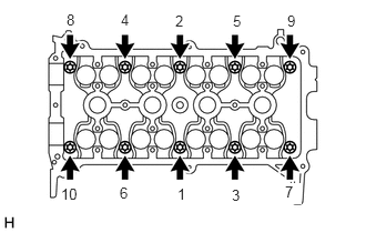
Using several steps, install and tighten the 10 cylinder head set bolts and 10 plate washers uniformly with an 8 mm bi-hexagon wrench, in the sequence shown in the illustration.
- Torque:
- 29.4 N*m (300 kgf*cm, 22 ft.*lbf)
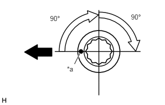
| *a | Paint Mark |

|
Engine Front |
Mark the front of the cylinder head set bolt with paint.
Retighten the cylinder head set bolts 90° and then an additional by 90° as shown in the illustration.
Check that the paint mark is now at a 180° angle from the engine front.
Wipe off any excess seal packing that seeped out.
13511
4.INSTALL CAMSHAFT
13512
5.INSTALL NO. 2 CAMSHAFT
13506
6.INSTALL CHAIN SUB-ASSEMBLY
13559
7.INSTALL CHAIN TENSIONER SLIPPER
13540
8.INSTALL NO. 1 CHAIN TENSIONER ASSEMBLY
15100C
9.INSTALL OIL PUMP SEAL
15100
10.INSTALL OIL PUMP ASSEMBLY
12315A
11.INSTALL ENGINE MOUNTING BRACKET RH
16100
12.INSTALL ENGINE WATER PUMP ASSEMBLY
16173
13.INSTALL WATER PUMP PULLEY
11101J
14.INSTALL CAMSHAFT TIMING OIL CONTROL VALVE ASSEMBLY
15100Q
15.INSTALL CRANKSHAFT POSITION SENSOR
13407
16.INSTALL CRANKSHAFT DAMPER SUB-ASSEMBLY
12305
17.INSTALL ENGINE MOUNTING INSULATOR SUB-ASSEMBLY RH
11201
18.INSTALL CYLINDER HEAD COVER SUB-ASSEMBLY
19500D
19.INSTALL NO. 1 IGNITION COIL
25591
20.INSTALL MANIFOLD SUPPORT BRACKET
82121
21.CONNECT ENGINE WIRE
Connect the engine wire to the cylinder head sub-assembly.
Connect the engine wire to the cylinder head sub-assembly with the 2 bolts.
- Torque:
- 8.4 N*m (86 kgf*cm, 74 in.*lbf)
44772
22.CONNECT CHECK VALVE TO CONNECTOR TUBE HOSE
16268
23.INSTALL NO. 1 WATER BY-PASS PIPE
89615
24.INSTALL KNOCK SENSOR
11452
25.INSTALL OIL LEVEL DIPSTICK GUIDE
Apply engine oil to a new O-ring.
Install the O-ring to the oil level dipstick guide.
- NOTICE:
-
Do not twist the O-ring.
Install the oil level dipstick guide to the cylinder block sub-assembly with the bolt.
- Torque:
- 10 N*m (102 kgf*cm, 7 ft.*lbf)
Engage the clamp to connect the engine wire to the oil level dipstick guide.
17111
26.INSTALL INTAKE MANIFOLD WITH THROTTLE BODY WITH MOTOR ASSEMBLY
Install a new intake manifold to head gasket to the intake manifold.
Install the intake manifold with throttle body with motor assembly to the cylinder head sub-assembly with the 3 bolts and 2 nuts.
- Torque:
- 30 N*m (306 kgf*cm, 22 ft.*lbf)
Engage the 3 clamps to install the engine wire to the 3 wire harness clamp brackets.
Connect the throttle body with motor assembly connector.
Engage the 2 clamps to connect the engine wire to the 2 wire harness clamp brackets.
Connect the water by-pass hose to the throttle body with motor assembly with the hose clip.
Connect the No. 2 water by-pass hose to the throttle body with motor assembly with the hose clip.
Engage the clamp to connect the No. 2 water by-pass hose to the hose clamp.
15301
27.INSTALL OIL LEVEL DIPSTICK SUB-ASSEMBLY
44774
28.CONNECT UNION TO CONNECTOR TUBE HOSE
Connect the union to connector tube hose to the intake manifold with the hose clip.
12261
29.INSTALL VENTILATION HOSE
16502
30.INSTALL WATER FILLER SUB-ASSEMBLY
16573B
31.CONNECT NO. 3 RADIATOR HOSE
32.CONNECT RADIATOR RESERVOIR TANK HOSE
87246
33.CONNECT OUTLET HEATER WATER HOSE
87245
34.CONNECT INLET HEATER WATER HOSE
23901
35.CONNECT FUEL TUBE SUB-ASSEMBLY
23842A
36.INSTALL EFI FUEL PIPE CLAMP
17361M
37.INSTALL AIR TUBE (for Automatic Transaxle)
74431
38.INSTALL BATTERY TRAY
28800
39.INSTALL BATTERY
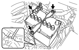
| *1 | Battery Clamp Bolt |
| *2 | Battery Carrier Assembly |
Install the battery to the battery tray.
Install the battery clamp sub-assembly to the battery carrier assembly with the 2 nuts and battery clamp bolt.
- Torque:
- 3.5 N*m (36 kgf*cm, 31 in.*lbf)
- HINT:
-
Engage the hook of the battery clamp bolt to the notch of the battery carrier assembly.
Connect the positive (+) battery terminal to the battery with the nut.
- Torque:
- 5.4 N*m (55 kgf*cm, 48 in.*lbf)
Install the terminal cover to the positive (+) battery terminal.
23820
40.INSTALL FUEL VAPOR FEED HOSE ASSEMBLY
17735
41.INSTALL AIR CLEANER CAP WITH NO. 1 AIR CLEANER HOSE
17341T
42.CONNECT NO. 1 AIR HOSE (for Automatic Transaxle)
23827A
43.CONNECT NO. 2 FUEL VAPOR FEED HOSE
23820
44.CONNECT FUEL VAPOR FEED HOSE ASSEMBLY
27060
45.INSTALL GENERATOR WITH REGULATOR ASSEMBLY
17410
46.INSTALL FRONT EXHAUST PIPE ASSEMBLY
57533B
47.INSTALL FRONT FLOOR CENTER BRACE
58910C
48.INSTALL REAR CONSOLE BOX ASSEMBLY
55781E
49.INSTALL COWL TOP VENTILATOR LOUVER SUB-ASSEMBLY
50.CONNECT CABLE TO NEGATIVE BATTERY TERMINAL
- Torque:
- 5.4 N*m (55 kgf*cm, 48 in.*lbf)
51.INSTALL FRONT WHEEL RH
- Torque:
- 103 N*m (1050 kgf*cm, 76 ft.*lbf)
52.ADD ENGINE COOLANT
53.ADD ENGINE OIL
54.INSPECT FOR ENGINE COOLANT LEAK
55.INSPECT ENGINE OIL LEVEL
56.INSPECT FOR ENGINE OIL LEAK
57.INSPECT FOR FUEL LEAK
58.INSPECT FOR EXHAUST GAS LEAK
59.INSPECT IGNITION TIMING
60.INSPECT ENGINE IDLING SPEED
61.INSPECT COMPRESSION
62.INSPECT CO/HC
51441C
63.INSTALL ENGINE UNDER COVER RH
51442C
64.INSTALL ENGINE UNDER COVER LH