Main Bearing, Crankshaft and Cylinder Block Removal and Installation
Precautions: General safety (00)
NOTICE:
If any of the parts listed below is reinstalled into a position different from the original position, engine problems could occur.
If these parts are to be reused, keep them in numerical order so that they can be reinstalled in their original positions.
•Main bearings
•Thrust bearings
•Thrust bearings
NOTE:
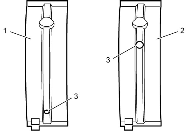

For ENG A-STOP model, main bearing No.1 upper half (1) and main bearing No.2 – 5 upper halves (2) have holes (3) in different positions.
Distinguish them for installation.
Removal
1)Remove engine assembly from vehicle. 
2)Remove flywheel (M/T model) or drive plate (A/T model).
3)Remove pistons and connecting rods.
4)Remove oil seal housing (1).
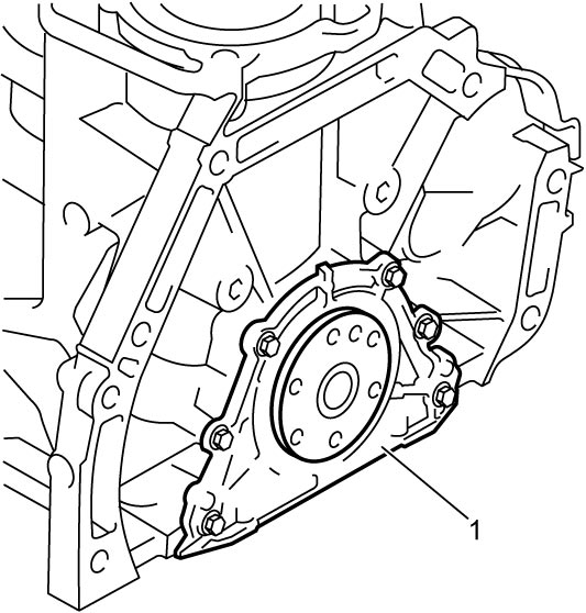
5)Remove rear oil seal from oil seal housing.
6)Remove CKP sensor.
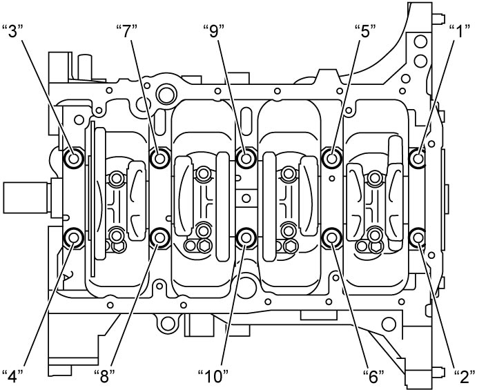
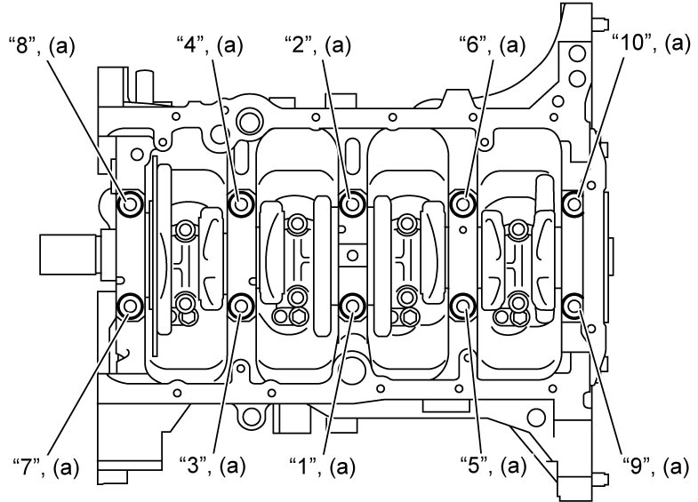
7)Remove main bearing cap bolts in numerical order (“1 – “10”) evenly and gradually.
8)Remove main bearing caps.
9)Remove crankshaft from cylinder block.
10) Remove sensor plate from crankshaft, if necessary.
NOTE:
Use T-30 security TORX® to loosen sensor plate screws.
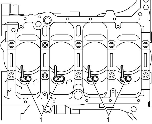
11)Remove piston cooling jets (1), if necessary.
12)Remove oil cooler, if necessary.
13)Remove generator, if necessary.
14)Remove water pump, if necessary.
15)Remove PCV valve, if necessary.
16)Remove breather plate (1), if necessary.
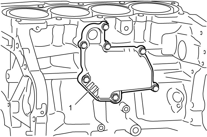
17)Remove knock sensor, if necessary.
18)Remove oil temperature sensor, if necessary.
Installation
NOTICE:
•The engine will seize up if it is operated when the parts listed below are not properly lubricated.
Lubricate all the friction surfaces of these parts with engine oil before installing them.
When main bearing cap bolts are reused, check that main bearing cap bolts are not deformed exceeding the service limit referring to “Main Bearing Cap Bolt” under Main Bearing Inspection:K14C.
Lubricate all the friction surfaces of these parts with engine oil before installing them.
—Crankshaft journals
—Main bearings (Sliding surface)
—Thrust bearings
•Using main bearing cap bolts that are deformed exceeding the service limit could lead to engine problems.—Main bearings (Sliding surface)
—Thrust bearings
When main bearing cap bolts are reused, check that main bearing cap bolts are not deformed exceeding the service limit referring to “Main Bearing Cap Bolt” under Main Bearing Inspection:K14C.
1)Install new oil temperature sensor, if removed.
2)Install knock sensor, if removed.
3)Install breather plate (1) as follows, if removed.
a)Fit gasket (2) to breather plate.
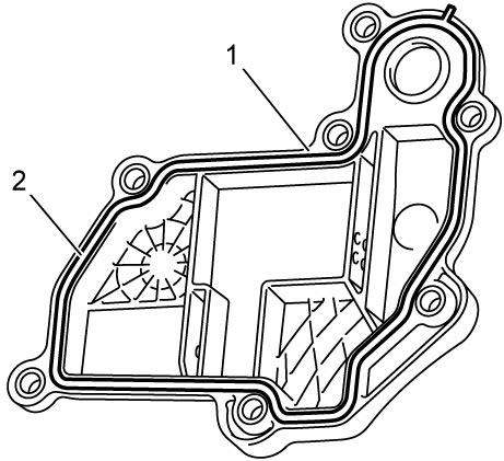
b)Install breather plate (1) to cylinder block, and then tighten breather plate bolts No.1 in numerical order (“1” – “6”) to specified torque.
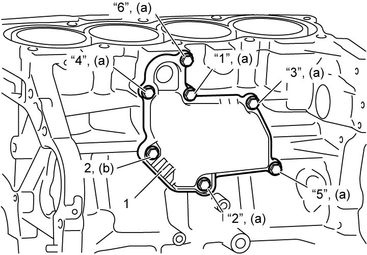
4)Install PCV valve, if removed.
5)Install water pump, if removed.
6)Install generator, if removed.
7)Install oil cooler, if removed.
8)Install piston cooling jets (1), if removed, and then tighten piston cooling jet bolts (2).
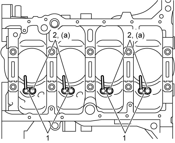
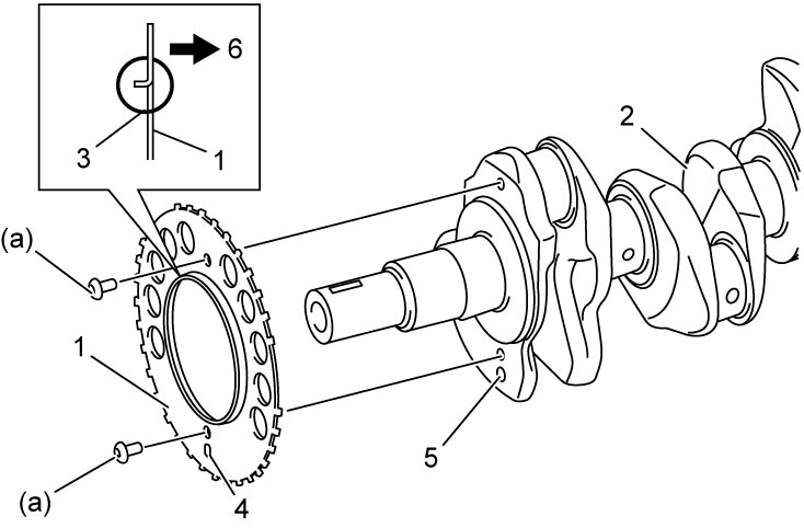
9)Install sensor plate (1) as follows, if removed.
a)Put sensor plate to crankshaft (2) facing the flange (3) outward and aligning the oblong hole (4) with crankshaft hole (5) as shown in figure.
10)Check that dowel pins are installed to cylinder block securely.
11)Install main bearings to cylinder block and main bearing caps as follows.
NOTICE:
If oil is present between the bearing backside and cylinder block or main bearing cap surface, the bearing could heat up to very high temperature, resulting in seizure.
Thoroughly wipe off any trace of oil that is present between the bearing backside and cylinder block or main bearing cap surface.
NOTE:
•Install main bearing halves (1) with oil groove (2) to cylinder block.
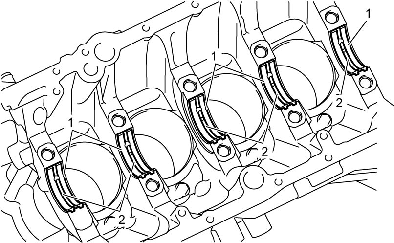 •Install other main bearing halves without oil groove to main bearing caps.
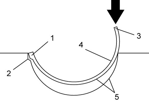
a)Check mating surfaces (5) of bearing backside and corresponding cylinder block and main bearing cap are clean and dry.
b)Fit the tab (1) on each bearing into groove (2) in cylinder block and main bearing cap.
c)Press bearing end (3) until it fully seats in cylinder block and main bearing cap.
d)Apply engine oil to sliding surface (4) of main bearing halves at cylinder block side.
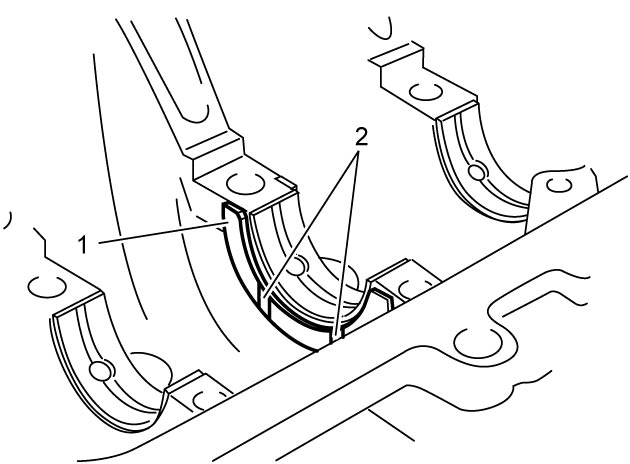
12)Apply engine oil to thrust bearings (1) and install them to cylinder block between No.2 and No.3 cylinders with oil grooves (2) facing outward.
13)Check cleanliness of crankshaft journal and place crankshaft on cylinder block and then apply engine oil to crankshaft journal.
14)Install main bearing caps according to the following procedure.
NOTICE:
Using main bearing cap bolts that are deformed exceeding the service limit could lead to engine problems.
Before installing main bearing cap, check that main bearing cap bolts are not deformed exceeding the service limit referring to “Main Bearing Cap Bolt” under Main Bearing Inspection:K14C.
NOTE:
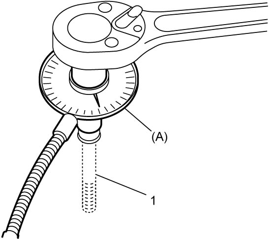
For accurate angle tightening of main bearing cap bolt (1) it is recommended to use tightening angle gauge (special tool).
a)Check dowel pins are fitted to main bearing caps.
b)Point arrow mark on cap to crankshaft pulley side and set main bearing caps to cylinder block.
c)Apply engine oil to bolt thread and seat of main bearing cap bolts.
d)Tighten main bearing cap bolts to 20 N·m (2.0 kgf-m, 15.0 lbf-ft) in numerical order (“1” – “10”) as shown using a 12-point socket wrenches.
e)In the same manner as in Step c), tighten them to 40 N·m (4.1 kgf-m, 29.5 lbf-ft).
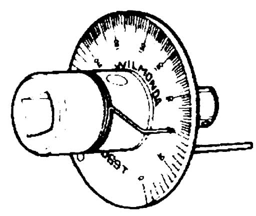
15)Check that crankshaft rotates smoothly when turning it by hand.
16)Install CKP sensor.
17)Clean sealing surface between oil seal housing and cylinder block.
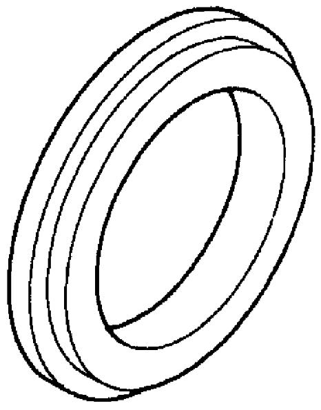
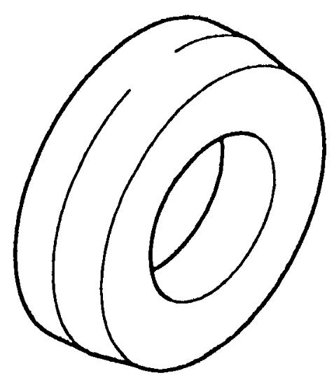
18)Install new rear oil seal (1) to oil seal housing (2) using special tool.
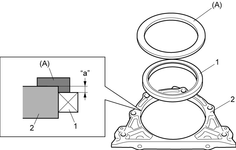
Rear oil seal installing position (depth)
“a”: 1.0 mm (0.039 in.)
19)Check that dowel pins (2) are installed to oil seal housing (1) as shown in figure.
20)Clean mating surfaces of cylinder block and oil seal housing.
21)Apply sealant to mating surface of oil seal housing (1).
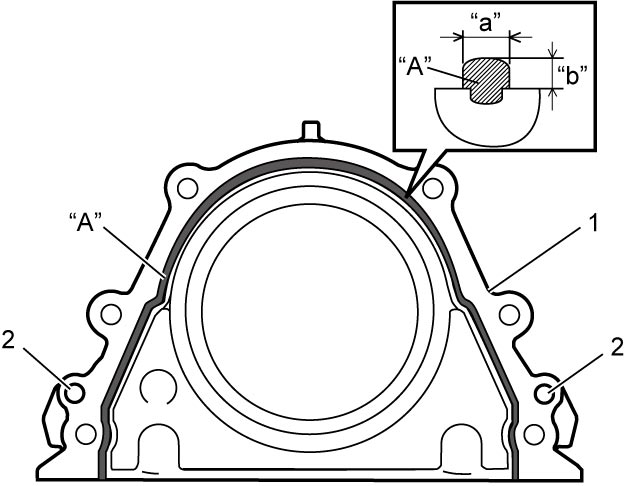
Sealant amount for oil seal housing
Width: “a”: 3 mm (0.12 in.)
Height “b”: 2 mm (0.08 in.)
22) Install oil seal housing (1) according to the following procedure.
a)Apply engine oil to oil seal lip.
b)Within 2 minutes after applying sealant, install oil seal housing using special tool to cylinder block.
NOTICE:
Turning over of oil seal lip or coming off of the inside spring will cause oil leakage.
While installing oil seal housing, pay attention not to turn over oil seal lip nor disengage the inside spring.
c)Tighten new oil seal housing bolts (2) to specified torque.
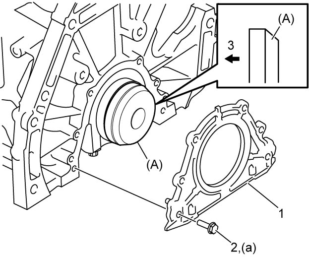
| 3. | Crankshaft side |
23)Install pistons and connecting rods.
24)Install flywheel (M/T model) or drive plate (A/T model).
25)Install cylinder head.
26)Install camshafts.
27)Install timing chain.
28)Install timing chain cover.
29)Install cylinder head cover.
30)Install oil pan.
31)Install engine assembly to vehicle.