REAR SUSPENSION REAR SUSPENSION MEMBER INSTALLATION
PROCEDURE

 41651
1.INSTALL REAR NO. 1 DIFFERENTIAL MOUNT CUSHION
41651A
2.INSTALL REAR NO. 2 DIFFERENTIAL MOUNT CUSHION
48790
3.TEMPORARILY INSTALL REAR UPPER CONTROL ARM ASSEMBLY LH
48770A
4.TEMPORARILY INSTALL REAR UPPER CONTROL ARM ASSEMBLY RH
- HINT:
-
Use the same procedure described for the LH side.
51206A
5.INSTALL REAR SUSPENSION MEMBER SUB-ASSEMBLY
Support the rear suspension member sub-assembly with an engine lifter using 4 attachments or equivalent tools.
- NOTICE:
- ·
Make sure to secure the rear suspension member sub-assembly to prevent it from dropping.
·Use the attachments to keep the rear suspension member sub-assembly level.
Raise the rear suspension member sub-assembly until there is no clearance between the rear suspension member sub-assembly and the vehicle body.
- NOTICE:
-
When raising the rear suspension member sub-assembly, be careful not to damage the vehicle body or other components installed on the vehicle.
While supporting the rear suspension member sub-assembly with a high transmission jack, using the 4 bolts B and 4 new bolts A, install the suspension member sub-assembly, front support rear LH, front support rear RH, rear support upper and rear support lower all together.
- NOTICE:
-
After temporarily tightening the bolts A in the order shown in the illustration, tighten them securely.
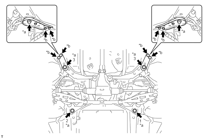
| *a | Bolt A (New bolt) | *b | Bolt B |
- Torque:
- 145 N*m (1479 kgf*cm, 107 ft.*lbf)
(Bolt A)
- 70 N*m (714 kgf*cm, 52 ft.*lbf)
(Bolt B)
48706B
6.TEMPORARILY INSTALL TOE CONTROL LINK SUB-ASSEMBLY LH
Install the toe control link sub-assembly LH and insert the toe adjust cam from the front of the vehicle. Then, install the No. 2 toe adjust plate and temporarily install a new nut.
- NOTICE:
-
Align the matchmarks on the rear suspension member and rear No. 2 suspension toe adjust plate.
48705
7.TEMPORARILY INSTALL TOE CONTROL LINK SUB-ASSEMBLY RH
- HINT:
-
Use the same procedure described for the LH side.
48740F
8.TEMPORARILY INSTALL REAR NO. 2 SUSPENSION ARM ASSEMBLY LH
Temporarily install the rear No. 2 suspension arm assembly LH to the rear suspension member with the bolt and a new nut.
- NOTICE:
-
Insert the bolt from inside the vehicle.
48730F
9.TEMPORARILY INSTALL REAR NO. 2 SUSPENSION ARM ASSEMBLY RH
- HINT:
-
Use the same procedure described for the LH side.
10.TEMPORARILY INSTALL REAR SHOCK ABSORBER WITH COIL SPRING LH
Temporarily install the rear shock absorber assembly to the rear No. 2 suspension arm with the bolt and a new nut.
- HINT:
-
The bolt may be inserted from either direction.
11.TEMPORARILY INSTALL REAR SHOCK ABSORBER WITH COIL SPRING RH
- HINT:
-
Use the same procedure described for the LH side.
48720A
12.TEMPORARILY INSTALL REAR NO. 1 SUSPENSION ARM ASSEMBLY LH
Temporarily install the rear No. 1 suspension arm assembly LH to the rear suspension member with the new bolt and new nut.
- NOTICE:
-
Insert the bolt from outside the vehicle.
48710A
13.TEMPORARILY INSTALL REAR NO. 1 SUSPENSION ARM ASSEMBLY RH
- HINT:
-
Use the same procedure described for the LH side.
48812
14.INSTALL REAR STABILIZER BAR
48802
15.TEMPORARILY TIGHTEN STABILIZER LINK SUB-ASSEMBLY (for LH Side)
48802
16.TEMPORARILY TIGHTEN STABILIZER LINK SUB-ASSEMBLY (for RH Side)
- HINT:
-
Use the same procedure described for the LH side.
46451B
17.INSTALL PARKING BRAKE CABLE SUPPORT BRACKET (for LH Side)
Install the parking brake cable support bracket with the bolt.
- Torque:
- 18 N*m (184 kgf*cm, 13 ft.*lbf)
46451B
18.INSTALL PARKING BRAKE CABLE SUPPORT BRACKET (for RH Side)
- HINT:
-
Use the same procedure described for the LH side.
77642A
19.INSTALL NO. 2 FUEL TANK PROTECTOR (for Clamp Type)
77641A
20.INSTALL NO. 1 FUEL TANK PROTECTOR (for Clamp Type)
77643A
21.INSTALL NO. 3 FUEL TANK PROTECTOR (for Metal Type)
46430
22.INSTALL NO. 3 PARKING BRAKE CABLE ASSEMBLY
Install the No. 3 parking brake cable assembly to the axle carrier with the clamp.
Install the No. 3 parking brake cable assembly to the rear suspension member lower stopper LH with the bolt.
- Torque:
- 18 N*m (184 kgf*cm, 13 ft.*lbf)
46420
23.INSTALL NO. 2 PARKING BRAKE CABLE ASSEMBLY
- HINT:
-
Use the same procedure described for the LH side.
42305
24.INSTALL REAR AXLE CARRIER SUB-ASSEMBLY LH
42304
25.INSTALL REAR AXLE CARRIER SUB-ASSEMBLY RH
- HINT:
-
Use the same procedure described for the LH side.
42340B
26.INSTALL REAR DRIVE SHAFT ASSEMBLY LH
42330
27.INSTALL REAR DRIVE SHAFT ASSEMBLY RH
- HINT:
-
Use the same procedure described for the LH side.
41110
28.INSTALL REAR DIFFERENTIAL CARRIER ASSEMBLY
37100
29.INSTALL PROPELLER WITH CENTER BEARING SHAFT ASSEMBLY
17430
30.INSTALL EXHAUST TAIL PIPE ASSEMBLY
89408C
31.INSTALL REAR HEIGHT CONTROL SENSOR SUB-ASSEMBLY LH (w/ HID Headlight System)
32.STABILIZE SUSPENSION
48790
33.FULLY TIGHTEN REAR UPPER CONTROL ARM ASSEMBLY LH
48770A
34.FULLY TIGHTEN REAR UPPER CONTROL ARM ASSEMBLY RH
- HINT:
-
Use the same procedure described for the LH side.
48706B
35.FULLY TIGHTEN TOE CONTROL LINK SUB-ASSEMBLY LH
48705
36.FULLY TIGHTEN TOE CONTROL LINK SUB-ASSEMBLY RH
- HINT:
-
Use the same procedure described for the LH side.
48740F
37.TEMPORARILY INSTALL REAR NO. 2 SUSPENSION ARM ASSEMBLY LH
Fully tighten the nut holding the rear shock absorber.
- Torque:
- 80 N*m (816 kgf*cm, 59 ft.*lbf)
Fully tighten the nut on the rear suspension member sub-assembly side.
- Torque:
- 80 N*m (816 kgf*cm, 59 ft.*lbf)
48730F
38.TEMPORARILY INSTALL REAR NO. 2 SUSPENSION ARM ASSEMBLY RH
- HINT:
-
Use the same procedure described for the LH side.
48802
39.FULLY TIGHTEN STABILIZER LINK SUB-ASSEMBLY (for LH Side)
48802
40.FULLY TIGHTEN STABILIZER LINK SUB-ASSEMBLY (for RH Side)
- HINT:
-
Use the same procedure described for the LH side.
48720A
41.FULLY TIGHTEN REAR NO. 1 SUSPENSION ARM ASSEMBLY LH
Fully tighten the bolt on the rear suspension member side of the rear No. 1 suspension arm assembly LH.
- Torque:
- 110 N*m (1122 kgf*cm, 81 ft.*lbf)
48710A
42.FULLY TIGHTEN REAR NO. 1 SUSPENSION ARM ASSEMBLY RH
- HINT:
-
Use the same procedure described for the LH side.
43.INSTALL REAR WHEELS
- Torque:
- 120 N*m (1224 kgf*cm, 89 ft.*lbf)
44.INSPECT AND ADJUST REAR WHEEL ALIGNMENT
45. VSC SENSOR NEUTRAL MEMORIZATION
46.CHECK FOR SPEED SENSOR SIGNAL
47. HEIGHT CONTROL SENSOR SIGNAL INITIALIZE (w/ HID Headlight System)
48.ADJUST HEADLIGHT AIMING (w/ HID Headlight System)