2AZ-FE ENGINE MECHANICAL CYLINDER HEAD INSTALLATION
CAUTION / NOTICE / HINT
- HINT:
-
Check whether the engine is TMC made or not by referring to the following illustration.
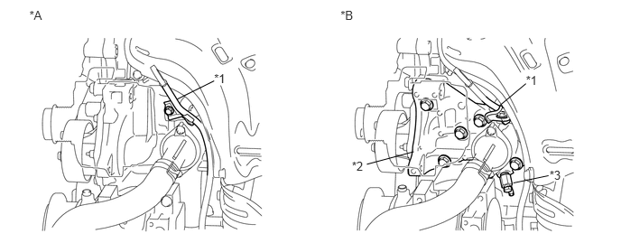 3.93,0.096 4.173,0.285 0.243,0.189 10 *B 0.339,0.096 0.588,0.285 0.249,0.189 10 *A 2.471,0.822 2.640,0.977 0.169,0.154 10 *1 2.471,0.932 2.045,1.143 false 6.069,0.84 6.239,0.994 0.169,0.154 10 *1 6.069,0.964 5.767,1.216 false 4.061,1.835 4.230,1.989 0.169,0.154 10 *2 6.342,1.937 6.511,2.092 0.169,0.154 10 *3 4.233,1.894 4.774,1.749 false 6.33,2.025 5.924,2.109 false
Text in Illustration *A for TMC Made Engine *B except TMC Made Engine *1 Engine Oil Level Dipstick Guide *2 Water Inlet Housing *3 Water Inlet Housing Drain Cock Assembly - -
PROCEDURE

 11115
1.INSTALL CYLINDER HEAD GASKET
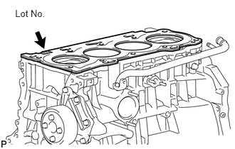
Place a new gasket on the cylinder block surface with the Lot No. stamp facing upward.
- NOTICE:
- ·
Remove any oil from the contact surfaces.
- ·
Be careful of the installation direction.
11101
2.INSTALL CYLINDER HEAD SUB-ASSEMBLY
Place the cylinder head on the head gasket.
- NOTICE:
-
Place the cylinder head gently in order to avoid damaging the gasket.
Install the cylinder head bolts.
- NOTICE:
-
The cylinder head bolts are tightened in 2 successive steps.
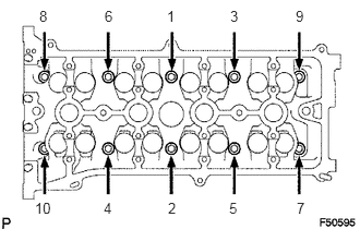
Apply a light coat of engine oil to the threads and under the heads of the cylinder head set bolts.
Using several steps, uniformly install and tighten the 10 cylinder head set bolts and plate washers with a 10 mm bi-hexagon wrench in the order shown in the illustration.
- Torque:
- 78.5 N*m (800 kgf*cm, 58 ft.*lbf)
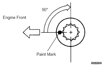
Mark the front of the cylinder head bolts with paint.
Further tighten the cylinder head bolts by 90° as shown in the illustration.
Check that the paint mark is now at a 90° angle to the front.
13050
3.INSTALL CAMSHAFT TIMING GEAR ASSEMBLY
Put the camshaft timing gear and camshaft together with the straight pin and key groove misaligned, as shown in the illustration.
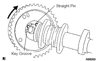
Turn the camshaft timing gear as shown in the illustration while pushing it gently against the camshaft. Push further at the position where the pin fits into the groove.
- NOTICE:
-
Be sure not to turn the camshaft timing gear to the retard angle side (the right angle).
Check that there is no clearance between the gear fringe and camshaft.
Tighten the flange bolt with the camshaft timing gear fixed in place.
- Torque:
- 54 N*m (551 kgf*cm, 40 ft.*lbf)
Check that the camshaft timing gear can move to the retard angle side (the right direction) and is locked in the most retarded position.
13523
4.INSTALL NO. 2 CAMSHAFT TIMING SPROCKET
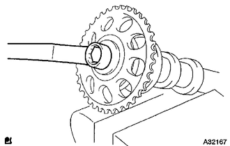
Clamp the camshaft in a vise, then install the camshaft timing sprocket with the bolt.
- Torque:
- 54 N*m (551 kgf*cm, 40 ft.*lbf)
- NOTICE:
-
Do not damage the camshaft.
13511
5.INSTALL CAMSHAFT
Apply a light coat of engine oil to the journal portion of the camshaft.
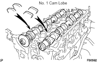
Place the 2 camshafts on the cylinder head with the No. 1 cam lobes facing the directions shown in the illustration.
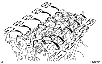
Examine the front marks and numbers, and check that the order is as shown in the illustration. Then install the bearing caps onto the cylinder head.
Apply a light coat of engine oil to the threads and under the heads of the bearing cap bolts.
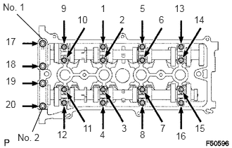
Using several steps, uniformly tighten the 20 bearing cap bolts in the sequence shown in the illustration.
- Torque:
- No. 1 and No. 2 bearing cap : 29.5 N*m (301 kgf*cm, 22 ft.*lbf)
- No. 3 bearing cap : 9.0 N*m (92 kgf*cm, 80 in.*lbf)
- NOTICE:
- ·
Determine the thrust direction of the camshaft by checking the location of the No. 1 and No. 2 bearing caps. Then tighten the bolts.
- ·
Install the camshaft with the timing mark of the camshaft timing gear on top.
13561
6.INSTALL NO. 1 CHAIN VIBRATION DAMPER
13506
7.INSTALL CHAIN SUB-ASSEMBLY
13559
8.INSTALL CHAIN TENSIONER SLIPPER
13566B
9.INSTALL TIMING CHAIN GUIDE
19315
10.INSTALL NO. 1 CRANKSHAFT POSITION SENSOR PLATE
11302
11.INSTALL TIMING CHAIN COVER SUB-ASSEMBLY
13540
12.INSTALL NO. 1 CHAIN TENSIONER ASSEMBLY
16620
13.INSTALL V-RIBBED BELT TENSIONER ASSEMBLY
13471
14.INSTALL CRANKSHAFT PULLEY
12101
15.INSTALL OIL PAN SUB-ASSEMBLY
11301K
16.INSTALL CRANKSHAFT POSITION SENSOR (for TMC Made Engine)
11301K
17.INSTALL CRANKSHAFT POSITION SENSOR (except TMC Made Engine)
11201
18.INSTALL CYLINDER HEAD COVER SUB-ASSEMBLY
19500
19.INSTALL IGNITION COIL ASSEMBLY
16603B
20.INSTALL IDLER PULLEY BRACKET
12305
21.INSTALL ENGINE MOUNTING INSULATOR RH
16611
22.INSTALL RADIATOR RESERVOIR BRACKET
16470
23.INSTALL RADIATOR RESERVOIR ASSEMBLY
27020
24.INSTALL GENERATOR ASSEMBLY
16361A
25.INSTALL FAN AND GENERATOR V BELT
51217A
26.INSTALL FRONT SUSPENSION MEMBER REINFORCEMENT RH
16571C
27.CONNECT NO. 1 RADIATOR HOSE
Connect the hose to the cylinder head.
11452
28.INSTALL ENGINE OIL LEVEL DIPSTICK GUIDE (for TMC Made Engine)
Apply a light coat of engine oil to a new O-ring and install it onto the guide.
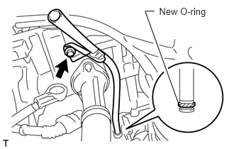
Install the guide with the bolt.
- Torque:
- 9.0 N*m (92 kgf*cm, 80 in.*lbf)
11452
29.INSTALL ENGINE OIL LEVEL DIPSTICK GUIDE (except TMC Made Engine)
Apply a light coat of engine oil to a new O-ring and install it onto the guide.
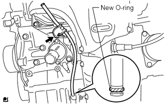
Install the guide with the bolt.
- Torque:
- 9.0 N*m (92 kgf*cm, 80 in.*lbf)
15301
30.INSTALL ENGINE OIL LEVEL DIPSTICK
25051
31.INSTALL EXHAUST MANIFOLD CONVERTER SUB-ASSEMBLY
Install a new gasket onto the cylinder head.
Temporarily tighten the exhaust manifold converter with the 5 nuts.
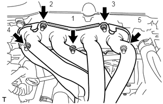
Tighten the 5 nuts in the sequence shown in the illustration.
- Torque:
- 37 N*m (377 kgf*cm, 27 ft.*lbf)
17167
32.INSTALL NO. 1 EXHAUST MANIFOLD HEAT INSULATOR
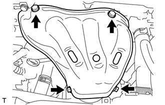
Install the exhaust manifold heat insulator with the 4 bolts.
- Torque:
- 12 N*m (122 kgf*cm, 9 ft.*lbf)
17139
33.INSTALL NO. 2 MANIFOLD STAY
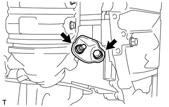
Install the stay with the bolt and nut.
- Torque:
- 44 N*m (449 kgf*cm, 32 ft.*lbf)
17118
34.INSTALL MANIFOLD STAY
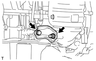
Install the stay with the bolt and nut.
- Torque:
- 44 N*m (449 kgf*cm, 32 ft.*lbf)
17410
35.INSTALL FRONT EXHAUST PIPE
36.CONNECT ENGINE WIRE
17135A
37.INSTALL INTAKE MANIFOLD INSULATOR
17111
38.INSTALL INTAKE MANIFOLD
23250
39.INSTALL FUEL DELIVERY PIPE WITH INJECTOR ASSEMBLY
Install the fuel delivery pipe with injector assembly (See page Engine / Hybrid System>2AZ-FE FUEL>FUEL INJECTOR>INSTALLATION).
11101J
40.INSTALL CAMSHAFT TIMING OIL CONTROL VALVE ASSEMBLY
22210
41.INSTALL THROTTLE BODY
87245A
42.CONNECT HEATER WATER INLET HOSE
Connect the heater water inlet hose.
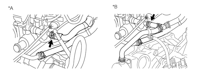
| *A | for Automatic Transaxle
for CVT (w/ Air Cooled Transmission Oil Cooler) |
| *B | for CVT (w/o Air Cooled Transmission Oil Cooler) |
17705
43.INSTALL AIR CLEANER CAP
44.INSTALL COWL TOP OUTER PANEL WITH WINDSHIELD WIPER MOTOR AND LINK
Install the cowl top outer panel with windshield wiper motor and link (See page Vehicle Interior>WIPER / WASHER>FRONT WIPER MOTOR>INSTALLATION).
45.ADD ENGINE OIL
46.CONNECT CABLE TO NEGATIVE BATTERY TERMINAL
47.INSPECT FOR FUEL LEAK
48.CHECK COMPRESSION
49.ADD ENGINE COOLANT
50.INSPECT FOR COOLANT LEAK
51.INSPECT FOR OIL LEAK
52.INSPECT FOR EXHAUST GAS LEAK
53.CHECK IGNITION TIMING
54.CHECK ENGINE IDLE SPEED
53701
56.INSTALL FRONT FENDER APRON RH
51441
57.INSTALL NO. 1 ENGINE UNDER COVER
58.INSTALL FRONT WHEEL RH
53292A
59.INSTALL UPPER RADIATOR SUPPORT SEAL
60.PERFORM INITIALIZATION
Perform initialization (See page General>INTRODUCTION>REPAIR INSTRUCTION>INITIALIZATION).
- NOTICE:
-
Certain systems need to be initialized after disconnecting and reconnecting the cable from the negative (-) battery terminal.