BRAKE BRAKE BOOSTER(for 2GR-FE) INSTALLATION
PROCEDURE

 44696
1.INSTALL CHECK VALVE GROMMET
Install the check valve grommet to the brake booster assembly.
44730
2.INSTALL BRAKE VACUUM CHECK VALVE ASSEMBLY
Install the brake vacuum check valve to the brake booster assembly.
44785
3.INSTALL BRAKE BOOSTER GASKET
Install a new brake booster gasket to the brake booster assembly.
47264D
4.INSTALL BRAKE MASTER CYLINDER PUSH ROD CLEVIS
Install the push rod clevis to the brake booster assembly.
Temporarily tighten the push rod clevis lock nut.
- HINT:
-
The push rod clevis lock nut will be tightened to a torque specification in the "CHECK AND ADJUST BRAKE PEDAL HEIGHT" procedures.
44610
5.INSTALL BRAKE BOOSTER ASSEMBLY
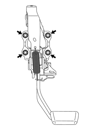
Install the brake booster assembly with the 4 nuts.
- Torque:
- 13 N*m (130 kgf*cm, 9 ft.*lbf)
11101J
6.INSTALL CAMSHAFT TIMING OIL CONTROL VALVE ASSEMBLY (for RHD)
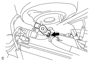
Apply engine oil to a new O-ring, and install it to the camshaft timing oil control valve assembly.
Install the camshaft timing oil control valve assembly with the bolt.
- Torque:
- 10 N*m (102 kgf*cm, 88 in.*lbf)
7.INSTALL WIRE HARNESS (for LHD)
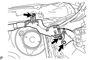
Install the wire harness to the body with the nut and 2 bolts.
8.INSTALL WIRE HARNESS (for RHD)
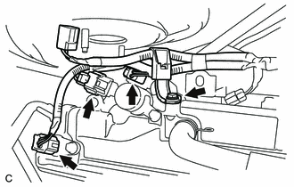
Install the wire harness to the engine assembly with the bolt.
- Torque:
- 7.0 N*m (71 kgf*cm, 62 in.*lbf)
Connect the 3 connectors.
9.INSTALL BRAKE LINE (for LHD)
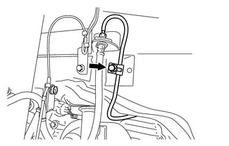
Install the brake line to the body with the bolt.
- Torque:
- 5.0 N*m (51 kgf*cm, 44 in.*lbf)
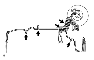
Engage the 5 clamps.
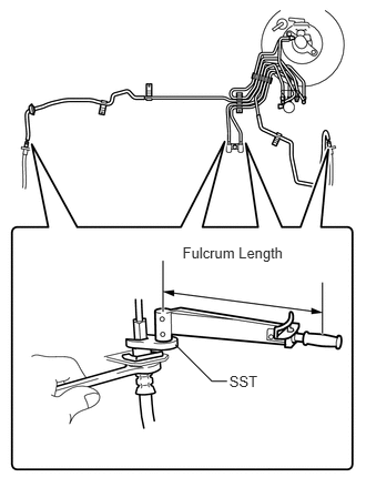
Using SST, connect the 4 brake lines.
- SST
- 09023-00101
- Torque:
- without SST : 15 N*m (155 kgf*cm, 11 ft.*lbf)
- with SST : 14 N*m (144 kgf*cm, 10 ft.*lbf)
- NOTICE:
- ·
Use a torque wrench with a fulcrum length of 250 mm (9.84 in.).
·This torque value is effective when SST is parallel to a torque wrench.
Using SST, connect the 6 brake lines to the brake actuator.
- SST
- 09023-00101
09023-38201
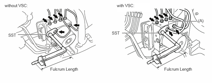
- Torque:
- except (A) without SST : 15 N*m (155 kgf*cm, 11 ft.*lbf)
- except (A) with SST : 14 N*m (144 kgf*cm, 10 ft.*lbf)
- (A) without SST : 20 N*m (199 kgf*cm, 14 ft.*lbf)
- (A) with SST : 18 N*m (185 kgf*cm, 13 ft.*lbf)
- NOTICE:
- ·
Use a torque wrench with a fulcrum length of 250 mm (9.84 in.).
·This torque value is effective when SST is parallel to a torque wrench.
10.INSTALL BRAKE LINE (for RHD)
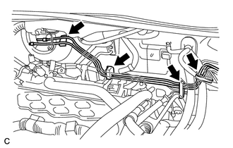
Engage the 4 clamps and install the 2 brake lines.
11.CONNECT VACUUM HOSE
Connect the vacuum hose to the brake vacuum check valve assembly with the clip.
47264A
12.INSTALL PUSH ROD PIN
Apply lithium soap base glycol grease to the push rod pin.
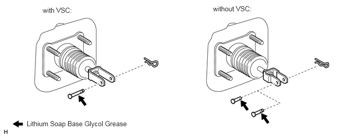
Install the push rod pin to the push rod clevis.
- NOTICE:
-
The push rod pin must be installed as shown in the illustration.
- HINT:
-
Each of push rod pins is interchangeable as shown in the illustration (without VSC).
Install a new clip to the push rod pin.
- NOTICE:
-
The clip must be installed as shown in the illustration.
- HINT:
-
Only the clips in the illustration will be supplied.
47201
13.INSTALL BRAKE MASTER CYLINDER SUB-ASSEMBLY (for LHD)
47201
14.INSTALL BRAKE MASTER CYLINDER SUB-ASSEMBLY (for RHD)
73900
15.INSTALL DRIVER SIDE KNEE AIRBAG ASSEMBLY (w/ Driver Side Knee Airbag)
55432B
16.INSTALL LOWER INSTRUMENT PANEL FINISH PANEL (w/o Driver Side Knee Airbag)
55432B
17.INSTALL LOWER INSTRUMENT PANEL FINISH PANEL (w/ Driver Side Knee Airbag)
55606
18.INSTALL NO. 1 INSTRUMENT PANEL UNDER COVER SUB-ASSEMBLY
55447C
19.INSTALL NO. 1 SWITCH HOLE BASE
55042B
20.INSTALL NO. 2 INSTRUMENT PANEL BOX DOOR SUB-ASSEMBLY
55660
21.INSTALL NO. 2 INSTRUMENT PANEL REGISTER ASSEMBLY
55420A
22.INSTALL INSTRUMENT CLUSTER FINISH PANEL CENTER ASSEMBLY
17190
23.INSTALL INTAKE AIR SURGE TANK ASSEMBLY (for RHD)
24.CONNECT CABLE TO NEGATIVE BATTERY TERMINAL
- NOTICE:
-
When disconnecting the cable, some systems need to be initialized after the cable is reconnected (See page General>INTRODUCTION>REPAIR INSTRUCTION>INITIALIZATION).
16470
25.INSTALL RADIATOR RESERVOIR TANK ASSEMBLY (for RHD)
26.ADD ENGINE COOLANT (for RHD)
27.INSPECT FOR COOLANT LEAK (for RHD)
51442
28.INSTALL NO. 2 ENGINE UNDER COVER (for RHD)
11209
29.INSTALL V-BANK COVER SUB-ASSEMBLY (for RHD)
53292A
30.INSTALL UPPER RADIATOR SUPPORT SEAL (for RHD)
31.INSTALL AIR CLEANER CASE SUB-ASSEMBLY
32.INSTALL AIR CLEANER CAP SUB-ASSEMBLY
33.INSTALL FRONT COWL TOP OUTSIDE PANEL WITH WINDSHIELD WIPER MOTOR LINK
34.INSTALL BRAKE MASTER CYLINDER RESERVOIR WITH BRACKET
55781F
35.INSTALL COWL TOP VENTILATOR LOUVER
53867H
36.INSTALL FRONT FENDER TO COWL SIDE SEAL LH
53866J
37.INSTALL FRONT FENDER TO COWL SIDE SEAL RH
38.INSTALL FRONT WIPER ARM AND BLADE ASSEMBLY LH
39.INSTALL FRONT WIPER ARM AND BLADE ASSEMBLY RH
85192
40.INSTALL FRONT WIPER ARM HEAD CAP
41.BLEED BRAKE SYSTEM
(See page Brake>BRAKE>BRAKE FLUID>BLEEDING)
42.INSPECT AND ADJUST BRAKE PEDAL
(See page Brake>BRAKE>BRAKE PEDAL>ADJUSTMENT)
43.INSPECT SRS WARNING LIGHT
Inspect SRS warning light (See page Vehicle Interior>SUPPLEMENTAL RESTRAINT SYSTEMS>AIRBAG SYSTEM>DIAGNOSIS SYSTEM).