INSTALLATION
Removal / installation · Vehicles built Jul 2007 – Jul 2009
Versions by build date: Jul 2007 – Jul 2009 Aug 2009 – Oct 2010 Nov 2010 – Oct 2012 Nov 2012 – Jul 2013 Aug 2013 – Jul 2014 from Aug 2014
| 1. INSTALL ENGINE WIRE |

Connect the connectors to the engine.
Engage the clamps to the engine.
Connect the connector to the knock sensor sub wire.
Install the ground wire onto the bank 2 cylinder head with the bolt.
- Torque:
- 8.0 N*m{ 82 kgf*cm , 71 in.*lbf }
Install the ground wire onto the bank 1 cylinder head with the bolt.
- Torque:
- 8.0 N*m{ 82 kgf*cm , 71 in.*lbf }
| 2. INSTALL OIL LEVEL GAUGE SUB-ASSEMBLY |
| 3. INSTALL OIL FILLER CAP HOUSING |
Install a new gasket.
Install the oil filler cap housing with the 2 nuts.
- Torque:
- 9.0 N*m{ 92 kgf*cm , 80 in.*lbf }
| 4. INSTALL OIL FILLER CAP SUB-ASSEMBLY |
| 5. INSTALL IGNITION COIL ASSEMBLY |
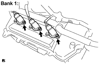  |
For Bank 1:
Install the 3 ignition coils with the 3 bolts.
- Torque:
- 10 N*m{ 102 kgf*cm , 7.4 ft.*lbf }
Connect the 3 ignition coil connectors.
For Bank 2: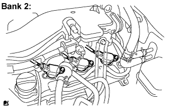
Install the 3 ignition coils with the 3 bolts.
- Torque:
- 10 N*m{ 102 kgf*cm , 7.4 ft.*lbf }
Connect the 3 ignition coil connectors.
| 6. INSTALL INTAKE MANIFOLD |
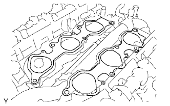 |
Set a new gasket on each cylinder head.
- NOTICE:
- Align the port holes of the gasket and cylinder head.
- Orient the gasket correctly.
- Align the port holes of the gasket and cylinder head.
Set the intake manifold on the cylinder heads.
Install and tighten the 10 bolts uniformly in several steps.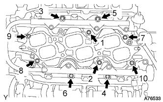
- Torque:
- 26 N*m{ 265 kgf*cm , 19 ft.*lbf }
Connect the 6 fuel injector connectors.
| 7. INSTALL NO. 1 IDLER PULLEY SUB-ASSEMBLY |
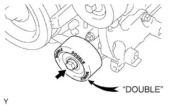 |
Install the idler pulley with the bolt.
- Torque:
- 39 N*m{ 398 kgf*cm , 29 ft.*lbf }
- HINT:
- DOUBLE is marked on the No. 1 idler pulley to distinguish it from the No. 2 idler pulley.
| 8. INSTALL NO. 2 IDLER PULLEY SUB-ASSEMBLY |
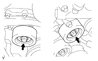 |
Install the 2 No. 2 idler pulleys with the 2 bolts.
- Torque:
- 54 N*m{ 551 kgf*cm , 40 ft.*lbf }
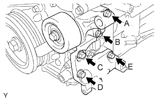
| 9. INSTALL V-RIBBED BELT TENSIONER ASSEMBLY |
 |
- NOTICE:
- The bolt in position A is not reusable.
- HINT:
- Each bolt length is as follows:
Position
Length
A
70 mm (2.76 in.)
B, C, D and E
33 mm (1.30 in.)
Use a new bolt in position A.
Finger-tighten the bolts in positions A and E and install the bracket.
Tighten the bolts in positions A and E.
- Torque:
- 36 N*m{ 267 kgf*cm , 27 ft.*lbf }
Tighten the bolts in positions B, C and D.
- Torque:
- 36 N*m{ 267 kgf*cm , 27 ft.*lbf }
| 10. INSTALL FRONT NO. 1 ENGINE MOUNTING BRACKET LH |
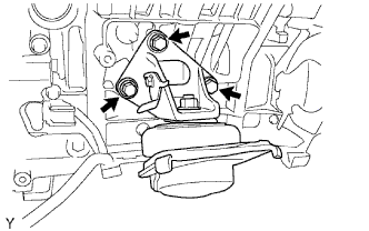 |
Install the engine mounting bracket with engine mounting insulator with the 3 bolts.
- Torque:
- 43 N*m{ 435 kgf*cm , 31 ft.*lbf }
| 11. INSTALL FRONT NO. 1 ENGINE MOUNTING BRACKET RH |
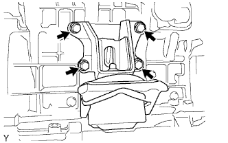 |
Install the engine mounting bracket with engine mounting insulator with the 4 bolts.
- Torque:
- 43 N*m{ 435 kgf*cm , 31 ft.*lbf }
| 12. INSTALL EXHAUST MANIFOLD SUB-ASSEMBLY LH |
Set a new gasket to the bank 2 cylinder head with the oval shape facing forward.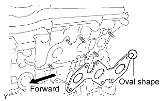
- NOTICE:
- Orient the new gasket correctly.
Install the exhaust manifold with the 6 nuts.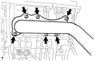
- Torque:
- 30 N*m{ 306 kgf*cm , 22 ft.*lbf }
Connect the air fuel ratio sensor connector.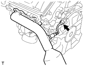
| 13. INSTALL NO. 2 MANIFOLD STAY |
Install the No. 2 manifold stay with the 3 bolts.
- Torque:
- 40 N*m{ 408 kgf*cm , 30 ft.*lbf }
| 14. INSTALL EXHAUST MANIFOLD SUB-ASSEMBLY RH |
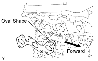 |
Set a new gasket to the bank 1 cylinder head with the oval shape facing forward.
- NOTICE:
- Orient the new gasket correctly.
Install the exhaust manifold with the 6 nuts.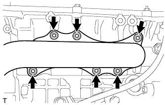
- Torque:
- 30 N*m{ 306 kgf*cm , 22 ft.*lbf }
Connect the air fuel ratio sensor connector.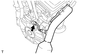
| 15. INSTALL MANIFOLD STAY |
Install the manifold stay with the 3 bolts.
- Torque:
- 40 N*m{ 408 kgf*cm , 30 ft.*lbf }
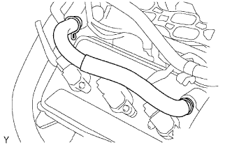
| 16. INSTALL NO. 2 VENTILATION HOSE |
 |
| 17. INSTALL VENTILATION HOSE |
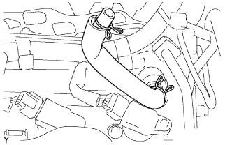 |
| 18. INSTALL HEATER WATER HOSE OUTLET |
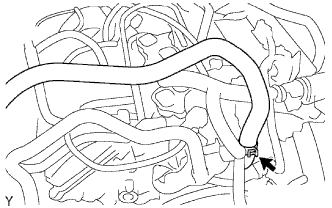 |
| 19. INSTALL HEATER WATER HOSE INLET |
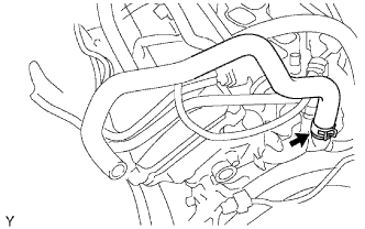 |
| 20. INSTALL ENGINE ASSEMBLY |
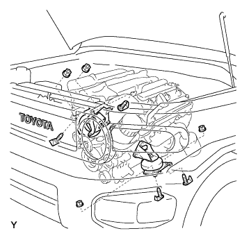 |
Attach the engine sling device and hang the engine with a chain block.
Lower the engine into the engine compartment carefully.
Attach the engine mounting brackets to the frame brackets.
Install the engine mounting brackets onto the frame brackets with the 4 bolts and 4 nuts.
- Torque:
- 38 N*m{ 387 kgf*cm , 28 ft.*lbf }
Remove the 4 bolts and 2 engine hangers.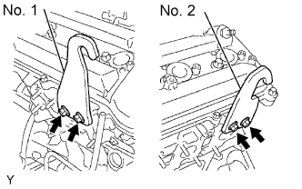
| 21. INSTALL ENGINE WIRE |
Connect the front differential connector (for Automatic Transmission 4WD).
Install the ground wire with the bolt and engage the clamp.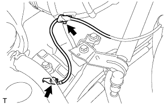
- Torque:
- 8.4 N*m{ 85 kgf*cm , 74 in.*lbf }
Connect the 2 connectors to the A/C unit.
Connect the 3 connectors to the ECM.
Connect the connector to the four wheel drive ECU (for Automatic Transmission 4WD).
Install the glove compartment door (Click here).
| 22. INSTALL NO. 2 ENGINE WIRE |
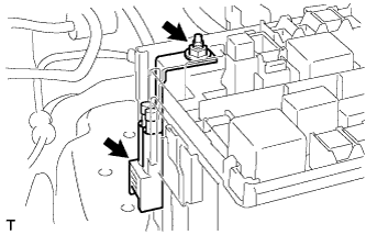 |
Install the engine wire onto the engine room relay block with the nut.
- Torque:
- 10 N*m{ 102 kgf*cm , 7.4 ft.*lbf }
Connect the connector to the engine room relay block.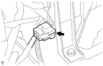
Install the ground wire onto the frame with the bolt.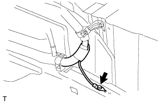
- Torque:
- 19 N*m{ 195 kgf*cm , 14 ft.*lbf }
Install the ground wire onto the body with the bolt.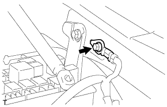
- Torque:
- 8.4 N*m{ 85 kgf*cm , 7.4 in.*lbf }
| 23. CONNECT HEATER WATER OUTLET HOSE |
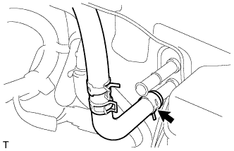 |
| 24. CONNECT HEATER WATER HOSE INLET |
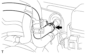 |
| 25. CONNECT NO. 2 FUEL PIPE SUB-ASSEMBLY |
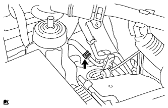 |
Connect the No. 2 fuel pipe.
| 26. CONNECT NO. 1 FUEL PIPE SUB-ASSEMBLY |
Connect the connector to the lower pipe. Push the two parts together firmly until a click sound is heard.
Check that the connector and lower pipe are securely connected by trying to pull them apart.
Connect the pipe to the clamp.
| 27. INSTALL VANE PUMP ASSEMBLY |
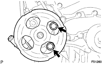 |
Install the vane pump assembly with the 2 bolts.
- Torque:
- 43 N*m{ 438 kgf*cm , 32 ft.*lbf }
Install the wire harness clamp bracket with the bolt.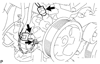
- Torque:
- 8.0 N*m{ 82 kgf*cm , 71 in.*lbf }
Connect the oil pressure switch connector.
- NOTICE:
- Make sure that no oil adheres to the connector.
| 28. INSTALL COOLER COMPRESSOR ASSEMBLY |
Install the cooler compressor assembly with the 4 bolts.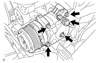
- Torque:
- 24.5 N*m{ 250 kgf*cm , 18 ft.*lbf }
Connect the cooler compressor assembly connector.
Install the suction hose sub-assembly with the bolt.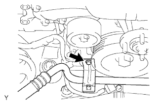
- Torque:
- 7.8 N*m{ 80 kgf*cm , 69 in.*lbf }
| 29. INSTALL GENERATOR ASSEMBLY |
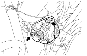 |
Install the generator assembly with the 2 bolts.
- Torque:
- 43 N*m{ 438 kgf*cm , 32 ft.*lbf }
Install the wire harness clamp bracket with the 2 bolts.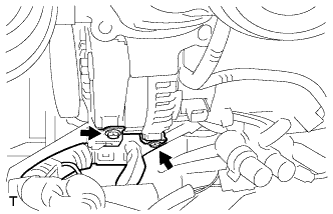
- Torque:
- 8.0 N*m{ 82 kgf*cm , 71 in.*lbf }
Connect the wire harness.
Connect the wire harness to terminal B and install the nut.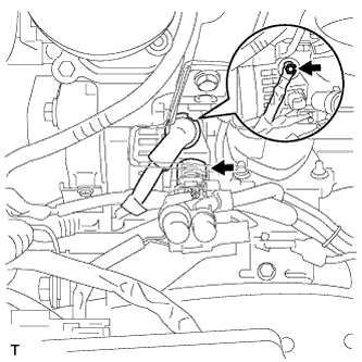
- Torque:
- 10 N*m{ 100 kgf*cm , 7 ft.*lbf }
Connect the connector to the generator assembly.
Install the wire harness stay with the bolt.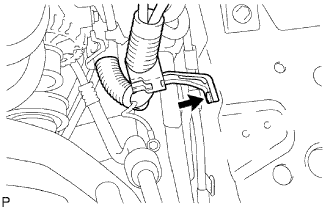
- Torque:
- 5.8 N*m{ 59 kgf*cm , 51 in.*lbf }
| 30. INSTALL INTAKE AIR SURGE TANK |
Install a new gasket onto the intake air surge tank.
Using a socket hexagon wrench 8, install the intake air surge tank with the 4 bolts.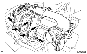
- Torque:
- 28 N*m{ 286 kgf*cm , 21 ft.*lbf }
Install the 2 nuts.
- Torque:
- 28 N*m{ 286 kgf*cm , 21 ft.*lbf }
Install the 3 wire harness clamps and hose clamp.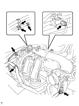
Connect the throttle body with motor connector.
Connect the 2 VSV connectors.
Connect the ventilation hose.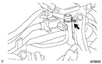
Connect the fuel vapor feed hose.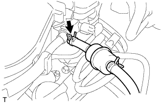
Connect the 2 water by-pass hoses.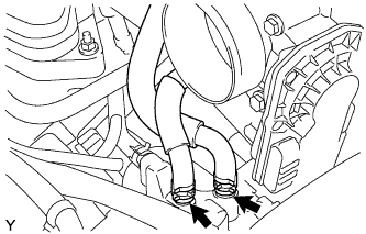
| 31. INSTALL NO. 2 SURGE TANK STAY |
Install the No. 2 surge tank stay with the 2 bolts.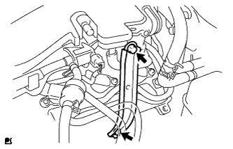
- Torque:
- 21 N*m{ 214 kgf*cm , 15 ft.*lbf }
| 32. INSTALL NO. 1 SURGE TANK STAY |
Install the No. 1 surge tank stay with the 2 bolts.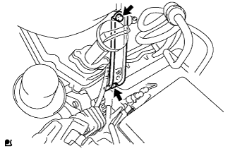
- Torque:
- 21 N*m{ 214 kgf*cm , 15 ft.*lbf }
| 33. INSTALL OIL BAFFLE PLATE |
Install the oil baffle plate with the bolt.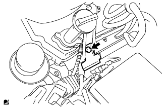
- Torque:
- 9.0 N*m{ 92 kgf*cm , 80 in.*lbf }
| 34. INSTALL THROTTLE BODY BRACKET |
Install the throttle body bracket with the 2 bolts.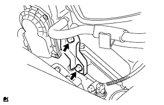
- Torque:
- 21 N*m{ 214 kgf*cm , 15 ft.*lbf }
| 35. INSTALL FLYWHEEL SUB-ASSEMBLY (for Manual Transmission) |
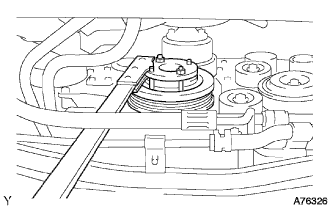 |
Using SST, hold the crankshaft.
- SST
- 09213-54015
(91651-60855)
09330-00021
Temporarily install the flywheel with the 8 new bolts.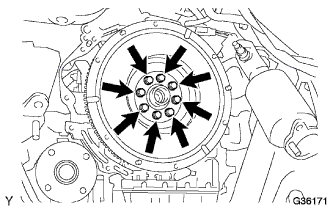
Install and tighten the 8 mounting bolts uniformly in several steps.
- Torque:
- 30 N*m{ 306 kgf*cm , 22 ft.*lbf }
Mark the top of the bolts with paint.
Tighten the 8 bolts 90° in the same sequence.
Check that the paint marks are now at a 90° angle to the top.
| 36. INSTALL DRIVE PLATE AND RING GEAR SUB-ASSEMBLY (for Automatic Transmission) |
|
|
Using SST, hold the crankshaft.
- SST
- 09213-54015
(91651-60855)
09330-00021
Apply adhesive to the 2 or 3 end threads of the bolts.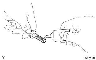
- Adhesive:
- Toyota Genuine Adhesive 1324, Three Bond 1324 or the equivalent.
Install the drive plate and 2 spacers onto the crankshaft.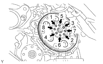
Install the drive plate with the 6 bolts in the order shown in the illustration.
- Torque:
- 83 N*m{ 846 kgf*cm , 61 ft.*lbf }
| 37. INSTALL CLUTCH DISC ASSEMBLY (for Manual Transmission) |
| 38. INSTALL MANUAL TRANSMISSION UNIT ASSEMBLY (for Manual Transmission) |
| 39. INSTALL AUTOMATIC TRANSMISSION ASSEMBLY (for Automatic Transmission) |
| 40. INSTALL RADIATOR ASSEMBLY |
| 41. INSTALL HOOD SUB-ASSEMBLY |
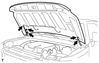 |
Install the hood with the 4 bolts.
Connect the windshield washer hose.
| 42. INSTALL HOOD SUPPORT |
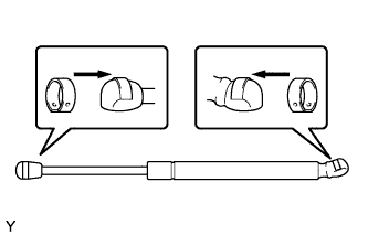 |
Install the 2 stop rings onto the hood support.
Install the hood support.
| 43. INSTALL BATTERY |
| 44. ADD ENGINE COOLANT |
Pour coolant into the radiator until it overflows.
- Capacity:
Transmission
Capacity
Manual Transmission
9.4 liters (9.9 Us qts, 8.3 Imp. qts)
Automatic Transmission
9.8 liters (10.4 Us qts, 8.6 Imp. qts)
- NOTICE:
- Do not substitute plain water for engine coolant.
- HINT:
- Use of improper coolants may damage the engine cooling system.
- Use only TOYOTA SLLC or similar high quality ethylene glycol based non-silicate, non-amine, non-nitrite, and non-borate coolant with long-life hybrid organic acid technology (coolant with long-life hybrid organic acid technology consists of a combination of low phosphates and organic acids).
- New TOYOTA vehicles are filled with TOYOTA SLLC (color is pink, premixed ethylene glycol concentration is approximately 50 % and freezing temperature is -35°C (-31°F)). When replacing the coolant, TOYOTA SLLC is recommended.
- Use of improper coolants may damage the engine cooling system.
Check the coolant level inside the radiator by squeezing the inlet and outlet radiator hoses several times by hand. If the coolant level goes down, add coolant.
Install the radiator cap securely.
Slowly pour coolant into the radiator reservoir until it reaches the FULL line.
Warm up the engine until the cooling fan operates.
Set the air conditioning as follows while warming up the engine.
Item
Condition
Fan Speed
Any setting except OFF
Temperature
Toward WARM
Air Conditioning Switch
OFF
Maintain the engine speed at 2,000 to 2,500 rpm and warm up the engine until the cooling fan operates.
- NOTICE:
- Make sure that the radiator reservoir still has some coolant in it.
- Pay attention to the needle of the water temperature meter. Make sure that the needle does not show an abnormally high temperature.
- If there is not enough coolant, the engine may burn out or overheat.
- Make sure that the radiator reservoir still has some coolant in it.
Squeeze the inlet and outlet radiator hoses several times by hand while warming up the engine to bleed the air.
- CAUTION:
-
When pressing the radiator hoses:
- Wear protective gloves.
- Be careful as the radiator hoses are hot.
- Keep your hands away from the fan.
- Wear protective gloves.
Stop the engine and wait until the coolant cools down.
Remove the radiator cap and check the coolant level inside the radiator.
If the coolant level is below the full level, repeat the operation until the coolant level remains at the full level.
Check the coolant level inside the radiator reservoir tank again. If it is below the full level, add coolant.
| 45. ADD ENGINE OIL |
Add fresh engine oil and install the oil filler cap.
- Engine Oil:
Oil Grade
Oil Viscosity (SAE)
ILSAC multigrade engine oil
- 5 W-30
- 10 W-30
- 5 W-30
- Oil Capacity:
Item
Specification
With oil filter change
5.2 liters (5.5 US qts, 4.6 lmp. qts)
Without oil filter change
4.9 liters (5.2 US qts, 4.3 lmp. qts)
Dry fill
6.0 liters (6.3 US qts, 5.3 lmp. qts)
Reinstall the oil filler cap.
| 46. PERFORM INITIALIZATION (for Automatic Transmission) |
| 47. INSPECT FOR COOLANT LEAK |
Fill the radiator with coolant and attach a radiator cap tester.
Pump it to 177 kPa (1.8 kgf/cm2 25.7 psi), then check for leakage.
| 48. INSPECT FOR ENGINE OIL LEAK |
| 49. INSPECT FOR FUEL LEAK |
| 50. INSPECT FOR EXHAUST GAS LEAK |
| 51. INSPECT IGNITION TIMING |
- NOTICE:
- Turn all the electrical systems OFF.
- Conduct the inspection when the cooling fan motor is turned OFF.
- Turn all the electrical systems OFF.
Warm up the engine.
When using the intelligent tester:
Connect the intelligent tester to the DLC3.
Select the following menu items: Powertrain / Engine and ECT / Date List / IGN Advance.
Inspect the ignition timing during idling.
- Ignition timing:
- 7 to 24°CA BTDC during idling (Transmission in neutral position)
Check that the ignition timing advances immediately when the engine speed is increased.
When not using intelligent tester: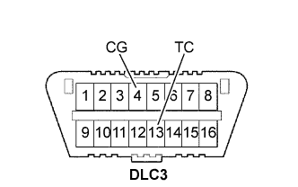
Using SST, connect the terminals 13 (TC) and 4 (CG) of the DLC3.
- SST
- 09843-18040
- NOTICE:
- Do not connect the terminals incorrectly as it causes breakage of the engine.
Remove the air cleaner.
Pull out the wire harness shown in the illustration.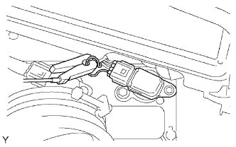
Connect the tester probe of a timing light to the wire of the ignition coil connector for the No. 1 cylinder.
- NOTICE:
- Use timing light that detects the first signal.
- Use timing light that detects the first signal.
- After checking, wrap the wire harness with tape.
- After checking, wrap the wire harness with tape.
Inspect the ignition timing during idling.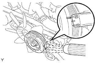
- Ignition timing:
- 8 to 12°CA BTDC during idling (Transmission in neutral position)
Remove SST from the DLC3.
Inspect the ignition timing during idling.
- Ignition timing:
- 7 to 24°CA BTDC during idling (Transmission in neutral position)
Install the air cleaner.
| 52. INSPECT ENGINE IDLING SPEED |
- NOTICE:
- Turn all the electrical systems OFF.
- Operate the inspection when the cooling fan motor is turned OFF.
- Turn all the electrical systems OFF.
Warm up the engine.
When using the intelligent tester:
Connect the intelligent tester to the DLC3.
Select the following menu items: Powertrain / Engine and ECT / Date List / Engine Speed.
Inspect the engine idling speed.
- Idling speed:
- 650 to 750 rpm (Transmission in neutral position)
When not using the intelligent tester: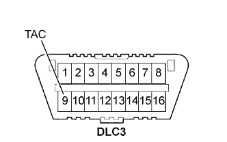
Using SST, connect the terminal 9 (TAC) of the DLC3.
- SST
- 09843-18030
Race the engine speed at 2500 rpm for approximately 90 seconds.
Inspect the engine idling speed.
- Idling speed:
- 650 to 750 rpm (Transmission in neutral position)
| 53. INSPECT COMPRESSION |
Warm up and stop the engine.
Remove the circuit opening relay (Click here).
Remove the V-bank cover (Click here).
Remove the air cleaner assembly (Click here).
Remove the throttle body bracket (Click here).
Remove the oil baffle plate (Click here).
Remove the No. 1 surge tank stay (Click here).
Remove the No. 2 surge tank stay (Click here).
Remove the ignition coils (Click here).
Remove the spark plugs.
Inspect the cylinder compression pressure.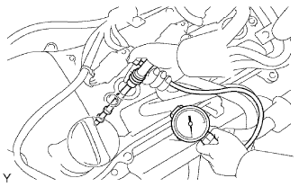
Insert a compression gauge into the spark plug hole. (*1)
Fully open the throttle. (*2)
While cranking the engine, measure the compression pressure. (*3)
- Compression pressure:
- 1300 kPa (13.3 kgf/cm2, 189 psi)
- Minimum pressure:
- 1000 kPa (10.2 kgf/cm2, 145 psi)
- Difference between cylinders:
- 100 kPa (1.0 kgf/cm2, 15 psi)
- NOTICE:
- Use a fully-charged battery so the engine speed can be increased to 2500 rpm or more.
- Use a fully-charged battery so the engine speed can be increased to 2500 rpm or more.
- Inspect the other cylinders in the same way.
- Inspect the other cylinders in the same way.
- Measure the compression in as short a time as possible.
- Measure the compression in as short a time as possible.
If the cylinder compression is low, pour a small amount of engine oil into the cylinder through the spark plug hole and repeat steps (*1) through (*3) for cylinders with low compression.
- If adding oil increases the compression, the piston rings and/or cylinder bore may be worn or damaged.
- If the pressure stays low, a valve may be stuck or seated improperly, or there may be leakage from the gasket.
- If adding oil increases the compression, the piston rings and/or cylinder bore may be worn or damaged.
| 54. INSPECT CO/HC |
Start the engine.
Run the engine at 2500 rpm for approximately 180 seconds.
Insert the CO/HC meter testing probe at least 40 cm (1.3 ft) into the tailpipe during idling.
Immediately check the CO/HC concentration during idling and/or while running at 2500 rpm.
- HINT:
- Complete the measurement within 3 minutes.
- Complete the measurement within 3 minutes.
- When carrying out the 2 mode (with the engine idling/running at 2500 rpm) test, the measurement orders are prescribed by the applicable local regulations.
- When carrying out the 2 mode (with the engine idling/running at 2500 rpm) test, the measurement orders are prescribed by the applicable local regulations.
If the CO/HC concentration does not comply with regulations, troubleshoot in the order given below.
Check the heated oxygen sensor operation.
CO
HC
Problems
Causes
Normal
High
Rough idling
- Faulty ignition:
- Incorrect timing
- Fouled, shorted or improperly gapped plugs
- Incorrect valve clearance
- Leaking intake and exhaust valves
- Leaking cylinders
Low
High
Rough idling
(Fluctuating HC reading)
- Vacuum leaks:
- PCV hoses
- Intake manifold
- Throttle body
- IAC valve
- Brake booster line
- Lean mixture causing misfire
High
High
Rough idling
(Black smoke from exhaust)
- Restricted air filter
- Plugged PCV valve
- Faulty EFI systems:
- Faulty pressure regulator
- Faulty engine coolant temperature sensor
- Faulty mass air flow meter
- Faulty ECM
- Faulty injectors
- Faulty throttle position sensor
- Faulty ignition:
| 55. INSPECT AND ADJUST FRONT WHEEL ALIGNMENT |