UA80F AUTOMATIC TRANSMISSION / TRANSAXLE AUTOMATIC TRANSAXLE ASSEMBLY(When Using the Engine Support Bridge) REMOVAL
PROCEDURE

 1. PRECAUTION
- NOTICE:
-
After turning the engine switch off, waiting time may be required before disconnecting the cable from the negative (-) battery terminal. Therefore, make sure to read the disconnecting the cable from the negative (-) battery terminal notices before proceeding with work.
-
Click hereGeneral>INTRODUCTION>REPAIR INSTRUCTION>PRECAUTION
2. ALIGN FRONT WHEELS FACING STRAIGHT AHEAD
3. SECURE STEERING WHEEL
4.DISCONNECT CABLE FROM NEGATIVE BATTERY TERMINAL
- NOTICE:
-
When disconnecting the cable, some systems need to be initialized after the cable is reconnected.
-
Click hereGeneral>INTRODUCTION>REPAIR INSTRUCTION>INITIALIZATION
5.REMOVE FRONT WHEELS
6.REMOVE WINDSHIELD WIPER MOTOR AND LINK ASSEMBLY
55701J
7.REMOVE OUTER COWL TOP PANEL SUB-ASSEMBLY (for LHD)
55701J
8.REMOVE OUTER COWL TOP PANEL SUB-ASSEMBLY (for RHD)
51441
9.REMOVE NO. 1 ENGINE UNDER COVER
51442
10.REMOVE NO. 2 ENGINE UNDER COVER
58166
11.REMOVE FRONT FLOOR COVER LH
53876A
12.SEPARATE FRONT FENDER LINER LH
53875A
13.SEPARATE FRONT FENDER LINER RH
53737B
14.REMOVE FRONT FENDER APRON SEAL LH
53736
15.REMOVE FRONT FENDER APRON SEAL RH
16.DRAIN ENGINE COOLANT
17.DRAIN AUTOMATIC TRANSAXLE FLUID
18.DRAIN TRANSFER OIL
28100
19.REMOVE STARTER ASSEMBLY
33820B
20.SEPARATE TRANSMISSION CONTROL CABLE ASSEMBLY
82121
21.DISCONNECT ENGINE WIRE
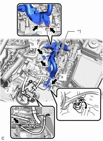
| *a | Transmission Wire Connector |
| *b | Park/Neutral Position Switch Assembly Connector |
| *1 | Engine Wire |
| *2 | Earth Wire |
Disconnect the park/neutral position switch assembly connector.
Disengage the claw, rotate the lever and disconnect the connector of the transmission wire connector.
Remove the 2 bolts and nut, disconnect the engine wire from the automatic transaxle case sub-assembly.
Remove the bolt to separate the earth wire.
Disengage the clamp to separate the engine wire.
35104V
22.SEPARATE BREATHER PLUG HOSE
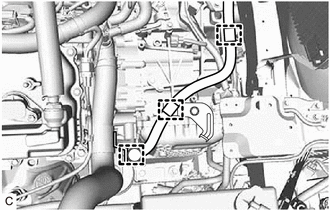
Disengage the 3 hose clamps to separate the breather plug hose.
16281K
23.DISCONNECT NO. 4 WATER BY-PASS HOSE
16267H
24.DISCONNECT NO. 3 WATER BY-PASS HOSE
16570
25.REMOVE RADIATOR PIPE ASSEMBLY
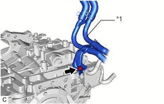
| *1 | Radiator Pipe Assembly |
Remove the bolt and radiator pipe assembly from the automatic transaxle assembly.
32942
26.DISCONNECT OUTLET NO. 1 OIL COOLER HOSE
32941
27.DISCONNECT NO. 1 TRANSMISSION OIL COOLER HOSE
47220D
28.SEPARATE BRAKE MASTER CYLINDER RESERVOIR ASSEMBLY (for LHD)
22030
29.REMOVE THROTTLE BODY WITH MOTOR ASSEMBLY
12261
30.DISCONNECT VENTILATION HOSE
25860
31.DISCONNECT PURGE VALVE (PURGE VSV)
17126
32.REMOVE NO. 2 SURGE TANK STAY
17190
33.REMOVE INTAKE AIR SURGE TANK ASSEMBLY
17176
34.REMOVE AIR SURGE TANK TO INTAKE MANIFOLD GASKET
35.REMOVE WIRE HARNESS CLAMP BRACKET
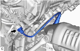
Disconnect the air fuel ratio sensor (for Bank 1) connector.
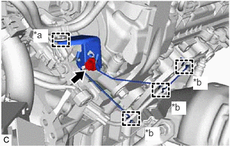
| *a | Hose Clamp |
| *b | Wire Harness Clamp |
Disengage the hose clamp and 3 wire harness clamps.
Remove the bolt and wire harness clamp bracket from the cylinder head RH.
17403
36.REMOVE FRONT NO. 3 EXHAUST PIPE SUB-ASSEMBLY
17584B
37.REMOVE NO. 1 EXHAUST PIPE SUPPORT BRACKET (for Lower Side)
17410
38.REMOVE FRONT EXHAUST PIPE ASSEMBLY
17118
39.REMOVE MANIFOLD STAY
17141
40.REMOVE EXHAUST MANIFOLD (TWC: Front Catalyst)
17173
41.REMOVE EXHAUST MANIFOLD TO HEAD GASKET (for Bank 1)
37100
42.REMOVE PROPELLER WITH CENTER BEARING SHAFT ASSEMBLY
48810
43.SEPARATE FRONT STABILIZER LINK ASSEMBLY LH
48820B
44.SEPARATE FRONT STABILIZER LINK ASSEMBLY RH
- HINT:
-
Use the same procedure as for the LH side.
43502H
45.REMOVE FRONT AXLE SHAFT NUT
89543
46.SEPARATE FRONT SPEED SENSOR
45220
47.SEPARATE STEERING INTERMEDIATE SHAFT ASSEMBLY
45470
48.SEPARATE TIE ROD ASSEMBLY LH
45460
49.SEPARATE TIE ROD ASSEMBLY RH
- HINT:
-
Use the same procedure as for the LH side.
50.SEPARATE STEERING LINK ASSEMBLY
48069
51.SEPARATE FRONT LOWER NO. 1 SUSPENSION ARM SUB-ASSEMBLY LH
48068
52.SEPARATE FRONT LOWER NO. 1 SUSPENSION ARM SUB-ASSEMBLY RH
- HINT:
-
Use the same procedure as for the LH side.
53.SEPARATE FRONT DRIVE SHAFT ASSEMBLY
43420
54.REMOVE FRONT DRIVE SHAFT ASSEMBLY LH
43420G
55.REMOVE FRONT DRIVE SHAFT HOLE SNAP RING (for LH Side)
48829A
56.SEPARATE FRONT NO. 1 STABILIZER BRACKET LH
48824A
57.SEPARATE FRONT NO. 1 STABILIZER BRACKET RH
- HINT:
-
Use the same procedure as for the LH side.
58.REMOVE FRONT STABILIZER BAR WITH FRONT STABILIZER LINK ASSEMBLY
Remove the front stabilizer bar with front stabilizer link assembly from the front frame assembly.
- NOTICE:
-
Use wire or an equivalent tool to secure the front stabilizer bar with front stabilizer link assembly.
59.REMOVE STEERING LINK ASSEMBLY
Remove the steering link assembly from the vehicle body.
32971
60.SEPARATE TRANSMISSION OIL THERMOSTAT
12361
61.SEPARATE FRONT ENGINE MOUNTING INSULATOR ASSEMBLY
12372A
62.SEPARATE ENGINE MOUNTING INSULATOR LH
12362
63.SEPARATE ENGINE MOUNTING INSULATOR RH
12380
64.SEPARATE REAR ENGINE MOUNTING INSULATOR ASSEMBLY
65.INSTALL ENGINE HANGER
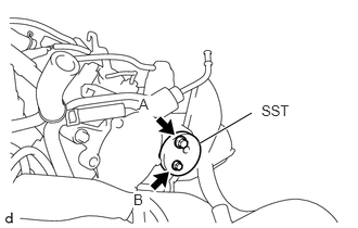
Install SST (engine hanger attachment) to the cylinder head RH with the 2 bolts.
- SST
- 09940-30010 (91671-10825)
- Torque:
- Bolt (A) : 33 N*m (337 kgf*cm, 24 ft.*lbf)
- Bolt (B) : 10 N*m (102 kgf*cm, 7 ft.*lbf)
| Item | Part No. |
|---|---|
| Bolt (A) | 91671-10825 |
| Bolt (B) | 91551-80620 |
- NOTICE:
-
Do not use any bolts other than the specified bolts.
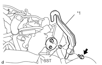
| *1 | No. 1 Engine Hanger |
Install SST (collar) and No. 1 engine hanger to SST (engine hanger attachment) with the bolt.
- SST
- 09940-30010 (09941-03010)
- Torque:
- 43 N*m (438 kgf*cm, 32 ft.*lbf)
| Item | Part No. |
|---|---|
| No. 1 Engine Hanger | 12281-36020 |
| Bolt | 91552-81050 |
- NOTICE:
-
Do not use any bolts other than the specified bolt.
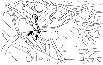
| *1 | No. 2 Engine Hanger |
Install the No. 2 engine hanger to the cylinder head LH with the 2 bolts.
- Torque:
- 33 N*m (337 kgf*cm, 24 ft.*lbf)
| Item | Part No. |
|---|---|
| No. 2 Engine Hanger | 12282-31100 |
| Bolt | 91671-10825 |
- NOTICE:
-
Do not use any bolts other than the specified bolts.
66.INSTALL ENGINE SUPPORT BRIDGE
Install SST to the vehicle body as shown in the illustration.
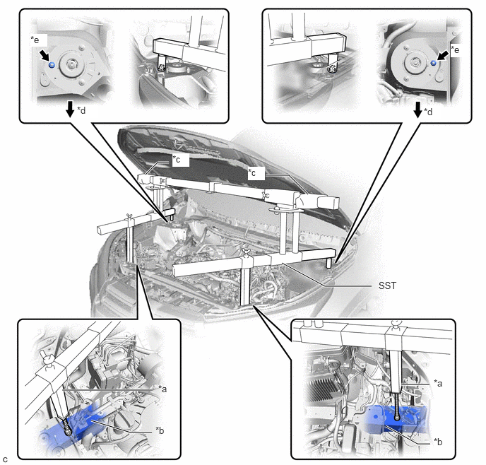
| *a | Support Shaft | *b | Front Side Member |
| *c | Cloth | *d | Front Side |
| *e | Front Suspension Nut | - | - |
- SST
- 09940-10020
- CAUTION:
- ·
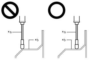 0.448,1.167 0.781,1.167 false 2.438,1.167 2.771,1.167 false 1.052,1.781 1.052,1.448 1.052,1.448 1.219,1.448 false 2.604,1.781 2.604,1.448 2.604,1.448 2.438,1.448 false 0.292,1.094 0.604,1.25 0.313,0.156 10 false *a 2.271,1.094 2.583,1.25 0.313,0.156 10 false *a 1.281,1.385 1.594,1.542 0.313,0.156 10 false *b 2.271,1.385 2.583,1.542 0.313,0.156 10 false *b
*a Support Shaft *b Front Side Member
Make sure that no oil or grease is on the front side member, and set the support shaft on the level surface of the front side member.
·The engine support bridge may fall off if there is any oil or grease on the front side member or it is installed on an unlevel surface.
- NOTICE:
- ·
Prevent SST from contacting the vehicle body exterior and windshield glass.
·To prevent damage to the engine hood, place pieces of cloth between the engine hood and SST.
·Lightly shake SST by hand to make sure it is securely installed before performing work.
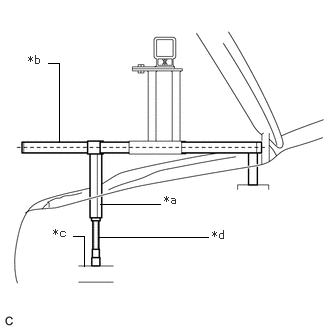
| *a | Support Shaft |
| *b | Sub Beam |
| *c | Front Side Member |
| *d | Threaded Portion |
Turn the threaded portion of each support shaft to adjust its height until the sub beams are parallel to the ground.
Install the chain block to the sling bracket.
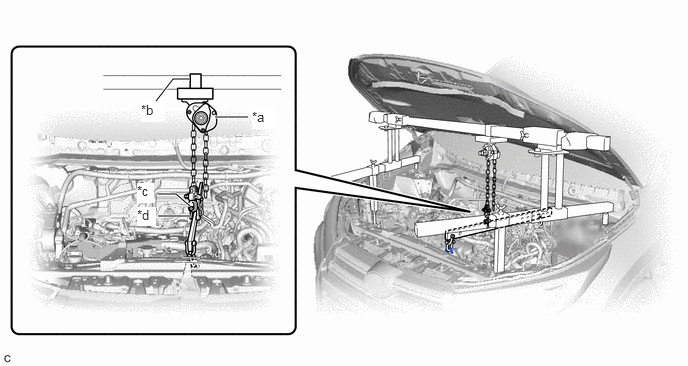
| *a | Chain Block | *b | Sling Bracket |
| *c | Fuse Shackle | *d | Shackle (A) |
Install the division bar to the chain block with the fuse shackle and shackle (A).
- CAUTION:
- ·
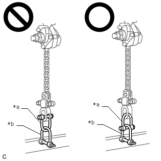 0.458,2.313 0.583,2.313 0.583,2.313 0.875,2.635 false 0.354,2.677 0.479,2.677 0.479,2.677 0.865,2.865 false 2.177,2.271 2.302,2.271 2.302,2.271 2.604,2.594 false 2.073,2.656 2.198,2.656 2.198,2.656 2.583,2.844 false 0.281,2.208 0.604,2.469 0.323,0.26 10 false *a 0.167,2.573 0.51,2.844 0.344,0.271 10 false *b 1.99,2.156 2.313,2.417 0.323,0.26 10 false *a 1.885,2.542 2.229,2.813 0.344,0.271 10 false *b
*a Fuse Shackle *b Shackle (A)
Make sure the fuse shackle is on the chain block side and the shackle (A) is on the division bar side as shown in the illustration so that the fuse bolt is visible and can be checked for deformation easily.
·If the fuse shackle is installed upside down, deformation of the fuse bolt will not be visible and cannot be used to tell if the load capacity of the engine support bridge has been exceeded. If the load capacity is exceeded, it may cause the engine support bridge to damage the vehicle and the engine assembly with automatic transaxle assembly may fall.
·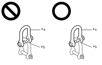 2.75,1 3.083,1 false 1.01,1 1.344,1 false 0.917,1.417 1.333,1.583 true 2.635,1.396 3.083,1.583 true 1.396,0.917 1.708,1.073 0.313,0.156 10 false *a 1.385,1.51 1.698,1.667 0.313,0.156 10 false *b 3.125,0.917 3.354,1.083 0.229,0.167 10 false *a 3.135,1.5 3.354,1.667 0.219,0.167 10 false *b
*a Fuse Shackle *b Fuse Bolt
Make sure that the fuse bolt of the fuse shackle is free of damage, such as deformation or cracks. If damaged, replace the fuse shackle.
·If a deformed fuse bolt is used, it cannot be used to tell if the load capacity of the engine support bridge has been exceeded. If the load capacity is exceeded, it may cause the engine support bridge to damage the vehicle and the engine assembly with transaxle assembly may fall.
Connect the division bar to the No. 1 engine hanger with the shackle (A).
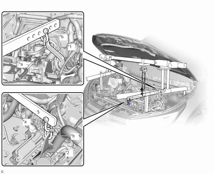
| *1 | No. 1 Engine Hanger | *2 | No. 2 Engine Hanger |
| *a | Division Bar | *b | Shackle (A) |
Connect the division bar to the No. 2 engine hanger with the 2 shackles (A).
Make sure the distance between the chain block assembly and suspension ring is 120 mm (4.72 in.) or more.
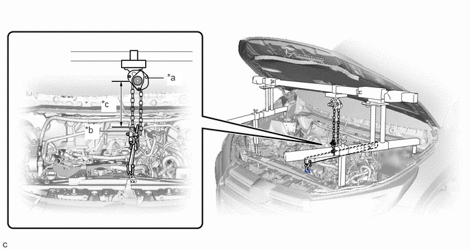
| *a | Chain Block Assembly | *b | Suspension Ring |
| *c | 120 mm or more | - | - |
Adjust the position of the chain block assembly so that the chain is perpendicular to the main beam and sub beams as shown in the illustration.
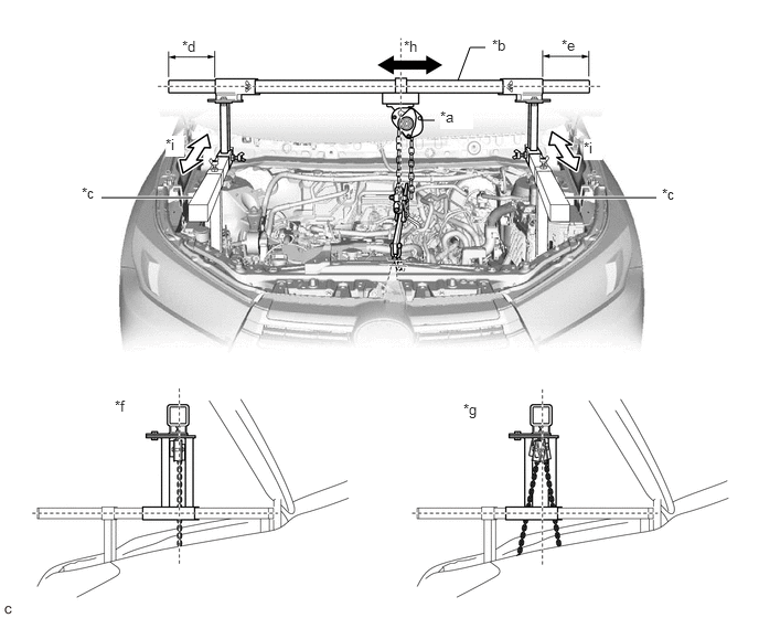
| *a | Chain Block Assembly | *b | Main Beam |
| *c | Sub Beam | *d | Dimension (A) |
| *e | Dimension (B) | *f | Correct |
| *g | Incorrect | *h | Right to Left Adjustment |
| *i | Front to Rear Adjustment | - | - |
- CAUTION:
-
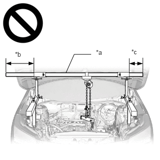 1.417,1.563 1.594,1.167 1.594,1.167 1.958,1.167 false 2.063,1.042 2.375,1.24 0.313,0.198 10 false *a 0.323,1.083 0.635,1.281 0.313,0.198 10 false *b 2.823,1.031 3.135,1.229 0.313,0.198 10 false *c
*a Main Beam *b Dimension (A) *c Dimension (B)
- ·
To prevent the engine assembly with automatic transaxle assembly from falling, make sure that the length of dimension (A) and dimension (B) are equal.
·Do not perform any procedures if the length of dimension (A) and dimension (B) are not equal.
·Performing any procedure when the length of dimension (A) and dimension (B) are not equal may cause the engine assembly with automatic transaxle assembly and engine support bridge to fall, possibly causing serious injury.
Tighten the 6 wing bolts and 2 bolts.
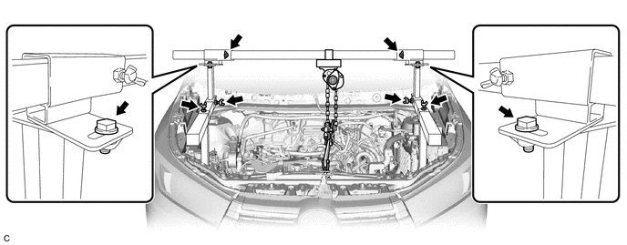
- Torque:
- 30 N*m (306 kgf*cm, 22 ft.*lbf)
- CAUTION:
-
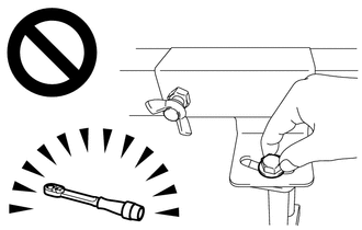
- ·
Do not perform any procedures before tightening the bolts to the specified torque.
·Performing procedures without tightening the bolts to the specified torque, may cause the engine support bridge to fall.
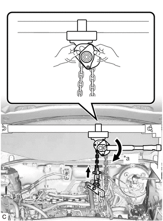
| *a | Turn |
Tighten the chain block assembly until it cannot be moved any further by hand.
- CAUTION:
-
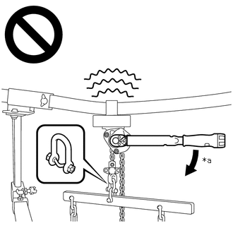 2.99,2.292 3.302,2.448 0.313,0.156 10 false *a
*a 41 N*m (418 kgf*cm, 30 ft.*lbf) or more
- ·
When suspending the engine assembly with automatic transaxle assembly, do not tighten the chain block assembly more than 41 N*m (418 kgf*cm, 30 ft.*lbf).
·Tightening the chain block assembly more than 41 N*m (418 kgf*cm, 30 ft.*lbf) will cause the load capacity (400 kg (881.8 lb)) to be exceeded and may cause damage to the engine support bridge and vehicle body.
11361J
67.REMOVE FLYWHEEL HOUSING UNDER COVER
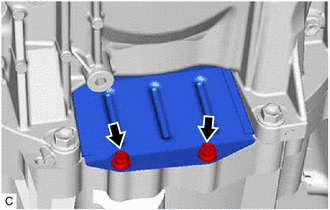
Remove the 2 bolts and flywheel housing under cover from the automatic transaxle case sub-assembly.
32101A
68.REMOVE DRIVE PLATE AND TORQUE CONVERTER ASSEMBLY SETTING BOLT
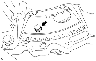
Turn the crankshaft to gain access to the 6 drive plate and torque converter assembly setting bolts and remove each drive plate and torque converter assembly setting bolt while holding the crankshaft pulley bolt with a wrench.
- HINT:
-
There will be one black colored drive plate and torque converter assembly setting bolt.
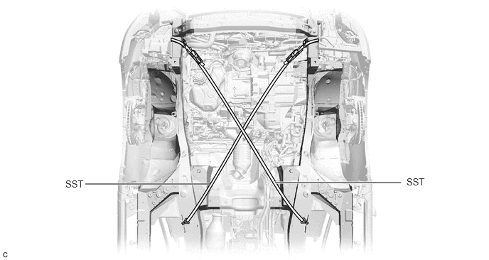
69.INSTALL BELT
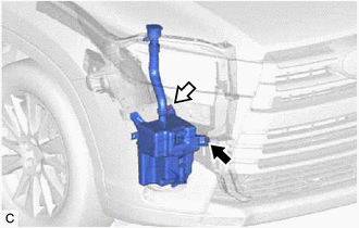

|
Bolt |

|
Nut |
Remove the bolt and nut and disconnect the windshield washer jar assembly from the vehicle body.
Install SST to the vehicle body as shown in the illustration.
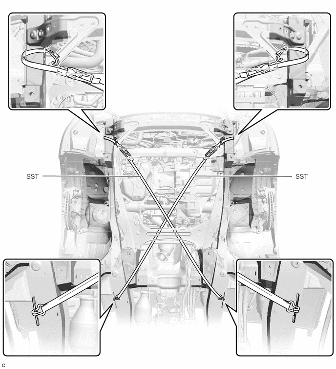
- SST
- 09727-00110
Using the ratchet buckle, tighten the 2 belts until there is no slack.
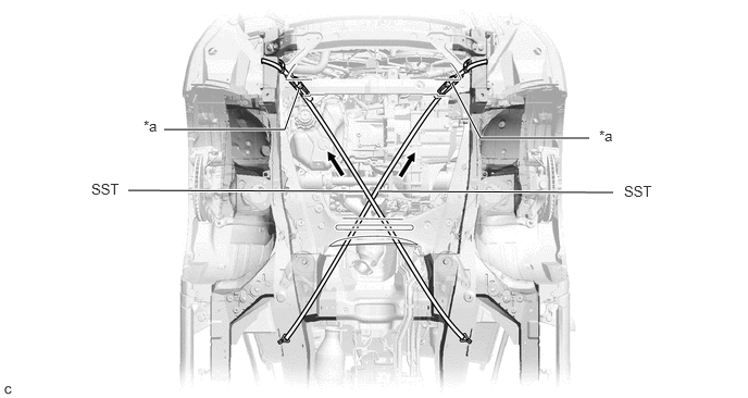
| *a | Ratchet Buckle | - | - |
51100G
70.REMOVE FRONT FRAME ASSEMBLY
36118A
71.REMOVE TRANSFER STIFFENER PLATE RH
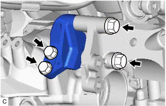
Remove the 4 bolts and transfer stiffener plate RH.
12362
72.REMOVE ENGINE MOUNTING INSULATOR RH
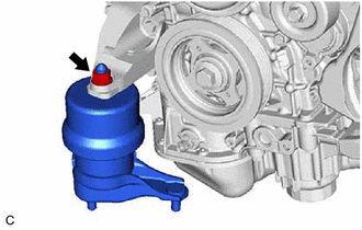
Remove the nut and engine mounting insulator RH from the engine mounting bracket RH.
43410
73.REMOVE FRONT DRIVE SHAFT ASSEMBLY RH
74.INSTALL ENGINE SUPPORT BAR
Install SST (support bar) to the engine mounting bracket RH with the stud bolt and nut as shown in the illustration.
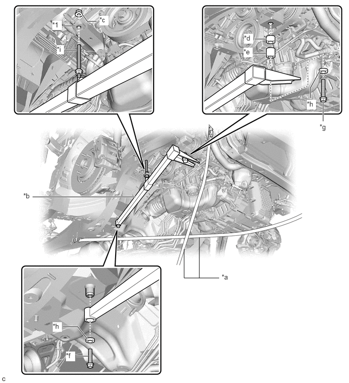
| *1 | Engine Mounting Bracket RH | - | - |
| *a | SST (Belt) | *b | SST (Support Bar) |
| *c | SST (Nut) | *d | SST (Spacer 20) |
| *e | SST (Spacer 30) | *f | SST (Bolt 40) |
| *g | SST (Bolt 90) | *h | SST (Washer) |
| *i | Stud Bolt | - | - |
- SST
- 09940-20011 (09941-02010, 09941-02020, 09941-02030, 09941-02040, 09941-02050, 09941-02060, 09941-02070)
- CAUTION:
-
To prevent the engine with automatic transaxle assembly from falling while servicing, do not remove SST (belt).
- HINT:
-
Tighten the nut by hand.
Install SST (support bar) to the vehicle body with the 2 bolts.
- Torque:
- 30 N*m (306 kgf*cm, 22 ft.*lbf)
12360
75.REMOVE FRONT ENGINE MOUNTING INSULATOR ASSEMBLY
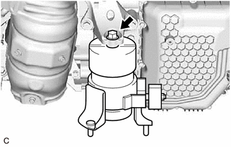
Remove the bolt and front engine mounting insulator assembly from the front engine mounting bracket.
12372A
76.REMOVE ENGINE MOUNTING INSULATOR LH
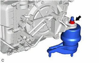
Remove the nut and engine mounting insulator LH from the automatic transaxle assembly.
77.SUPPORT ENGINE ASSEMBLY
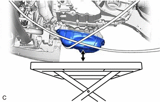
Set an engine lifter.
- CAUTION:
-
To prevent the engine assembly with automatic transaxle assembly from falling while servicing, do not remove SST.
- NOTICE:
-
Make sure that there is clearance between the engine oil pan assembly and engine lifter.
78.REMOVE BELT
Remove SST from the vehicle body.
30500
79.REMOVE AUTOMATIC TRANSAXLE ASSEMBLY
Support the automatic transaxle assembly with a transmission jack.
- NOTICE:
-
Secure the automatic transaxle assembly to the transmission jack using a suitable adapter, such as a rope or attachments.
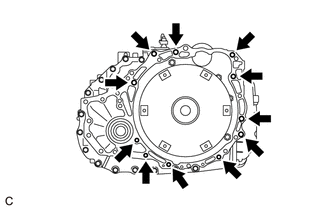
Remove the 11 bolts and automatic transaxle assembly.
- NOTICE:
-
To prevent damage to the knock pins, do not pry between the automatic transaxle assembly and engine assembly.
36100
80.REMOVE TRANSFER ASSEMBLY
81.DISCONNECT INLET NO. 2 OIL COOLER HOSE
82.DISCONNECT OUTLET NO. 3 OIL COOLER HOSE
32907C
83.REMOVE NO. 1 OIL COOLER TUBE SUB-ASSEMBLY WITHOUT HOSE
33493A
84.REMOVE TRANSMISSION OIL COOLER
12311A
85.REMOVE FRONT ENGINE MOUNTING BRACKET
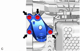
Remove the 4 bolts and front engine mounting bracket from the automatic transaxle assembly.
12325A
86.REMOVE ENGINE MOUNTING BRACKET LH
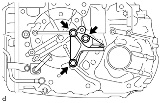
Remove the 3 bolts and engine mounting bracket LH from the automatic transaxle case sub-assembly.
87.REMOVE NO. 1 TRANSMISSION CONTROL CABLE BRACKET
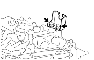
Remove the 2 bolts and No. 1 transmission control cable bracket from the automatic transaxle case sub-assembly.
88.REMOVE WIRE HARNESS CLAMP BRACKET
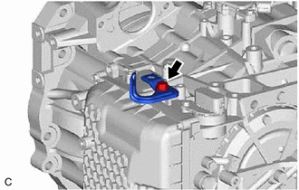
Remove the bolt and wire harness clamp bracket from the automatic transaxle case sub-assembly.
35150
89.REMOVE TRANSMISSION CASE PLUG ASSEMBLY
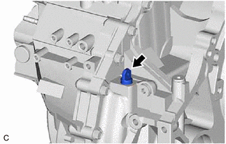
Remove the transmission case plug assembly from the automatic transaxle assembly.
35104V
90.REMOVE BREATHER PLUG HOSE
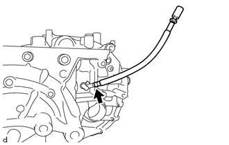
Using a screwdriver, remove the breather plug hose from the No. 1 breather plug (ATM).
- NOTICE:
-
Be careful not to damage the No. 1 breather plug (ATM).
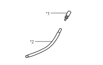
| *1 | Breather Plug Sub-assembly |
| *2 | Breather Plug Hose |
Remove the breather plug sub-assembly from the breather plug hose.
- NOTICE:
-
Be careful not to damage the breather plug sub-assembly.
32000
91.REMOVE TORQUE CONVERTER ASSEMBLY
Remove the torque converter assembly from the automatic transaxle assembly.
32000
92.INSPECT TORQUE CONVERTER ASSEMBLY
32101
93.INSPECT DRIVE PLATE AND RING GEAR SUB-ASSEMBLY