3UR-FE ENGINE MECHANICAL ENGINE ASSEMBLY REMOVAL
CAUTION / NOTICE / HINT
- CAUTION:
-
Some of these service operations affect the SRS airbag system. Read the precautionary notices concerning the SRS airbag system before servicing (See page Vehicle Interior>SUPPLEMENTAL RESTRAINT SYSTEMS>AIRBAG SYSTEM>PRECAUTION).
PROCEDURE

 1. PRECAUTION
- NOTICE:
-
After turning the ignition switch off, waiting time may be required before disconnecting the cable from the battery terminal. Therefore, make sure to read the disconnecting the cable from the battery terminal notice before proceeding with work (See page General>INTRODUCTION>REPAIR INSTRUCTION>PRECAUTION).
2.DISCHARGE FUEL SYSTEM PRESSURE
3.DISCONNECT CABLE FROM NEGATIVE BATTERY TERMINAL
- CAUTION:
-
Wait at least 90 seconds after disconnecting the cable from the negative (-) battery terminal to disable the SRS system.
- NOTICE:
-
When disconnecting the cable some systems need to be initialized after the cable is reconnected (See page General>INTRODUCTION>REPAIR INSTRUCTION>INITIALIZATION).
4.DRAIN ENGINE OIL
53301
5.REMOVE HOOD SUB-ASSEMBLY
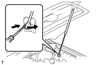
Using a screwdriver, release the 2 clips and remove the hood support assembly.
- HINT:
-
Tape the screwdriver tip before use.
- CAUTION:
-
Remove the hood support assembly while supporting the hood by hand.
Remove the 4 bolts and hood.
85110
6.REMOVE WINDSHIELD WIPER MOTOR ASSEMBLY
Remove the windshield wiper motor (See page Vehicle Exterior>WIPER / WASHER>FRONT WIPER MOTOR>REMOVAL).
55701J
7.REMOVE COWL TOP OUTER PANEL SUB-ASSEMBLY
Disconnect the 2 washer hoses.
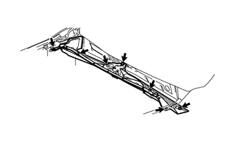
Remove the 7 bolts and outer panel.
16400
8.REMOVE RADIATOR ASSEMBLY
Remove the radiator assembly (See page Engine / Hybrid System>3UR-FE COOLING>RADIATOR>REMOVAL).
35000
9.REMOVE AUTOMATIC TRANSMISSION ASSEMBLY (for 2WD)
Remove the transmission assembly (See page Drivetrain>AB60E AUTOMATIC TRANSMISSION / TRANSAXLE>AUTOMATIC TRANSMISSION ASSEMBLY>REMOVAL).
35000
10.REMOVE AUTOMATIC TRANSMISSION ASSEMBLY (for 4WD)
Remove the transmission assembly (See page Drivetrain>AB60F AUTOMATIC TRANSMISSION / TRANSAXLE>AUTOMATIC TRANSMISSION ASSEMBLY>REMOVAL).
17700
11.REMOVE AIR CLEANER ASSEMBLY
17880
12.REMOVE AIR CLEANER HOSE ASSEMBLY
87245C
13.DISCONNECT INLET HEATER WATER HOSE C
87246C
14.DISCONNECT OUTLET HEATER WATER HOSE C
44750
15.DISCONNECT VACUUM HOSE ASSEMBLY
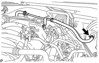
Disconnect the vacuum hose from the brake booster.
23820
16.REMOVE FUEL VAPOR FEED HOSE ASSEMBLY
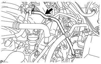
Remove the fuel vapor feed hose.
23801P
17.DISCONNECT FUEL MAIN AND RETURN HOSE
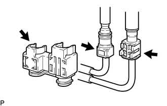
Remove the fuel pipe clamp.
Disconnect the fuel main and return hoses (See page Engine / Hybrid System>3UR-FE FUEL>FUEL SYSTEM>PRECAUTION).
89661
18.SEPARATE ECM
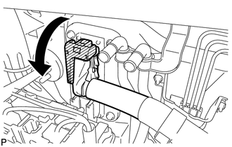
Disconnect the clamp and ECM connector.
- HINT:
-
Refer to the following procedures to disconnect the ECM connector (See page Engine / Hybrid System>3UR-FE ENGINE CONTROL>ECM>REMOVAL).
82121
19.SEPARATE ENGINE WIRE
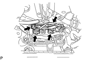
Disconnect the 4 connectors from the connector holder block.
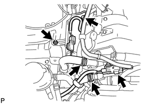
Remove the nut and connector bracket and disconnect the 2 air pump connectors.
Remove the bolt and disconnect the ground wire.
Disconnect the 2 air injection system hoses.
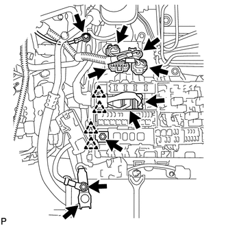
Remove the nut and disconnect the wire from the positive (+) battery cable.
Disconnect the cable from the positive (+) battery terminal.
Remove the bolt and disconnect the ground wire.
Disconnect the 4 air injection control driver connectors.
Remove the nut and disconnect the wire and 2 clips from the engine room junction block.
Disconnect the 2 connectors and 2 clips from the engine room junction block.
17343
20.DISCONNECT NO. 3 AIR INJECTION SYSTEM HOSE
17342
21.DISCONNECT NO. 2 AIR INJECTION SYSTEM HOSE
88320
22.SEPARATE COOLER COMPRESSOR ASSEMBLY
27020
23.REMOVE GENERATOR ASSEMBLY
Remove the generator assembly (See page Power Source / Network>3UR-FE BATTERY / CHARGING>GENERATOR>REMOVAL).
24.REMOVE EXHAUST MANIFOLD
Remove the exhaust manifold (See page Engine / Hybrid System>3UR-FE INTAKE / EXHAUST>EXHAUST MANIFOLD>REMOVAL).
32101
25.REMOVE DRIVE PLATE AND RING GEAR SUB-ASSEMBLY
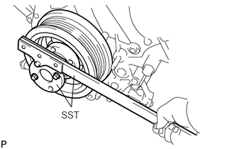
Using SST, hold the crankshaft.
- SST
- 09213-70011
09330-00021
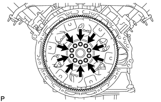
Remove the 10 bolts, rear drive plate spacer, drive plate and crankshaft angle sensor rotor.
16268
26.REMOVE NO. 1 WATER BY-PASS PIPE
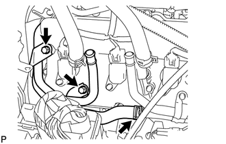
Remove the 2 bolts and disconnect the hose, and then remove the water by-pass pipe.
32907A
27.REMOVE OIL COOLER TUBE
Remove the bolt and oil cooler tube from the oil pan.
28.REMOVE ENGINE ASSEMBLY
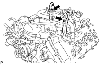
Install the 2 engine hangers with the 2 bolts as shown in the illustration.
- Torque:
- 43 N*m (438 kgf*cm, 32 ft.*lbf)
- HINT:
Item Part No. Engine hanger 12281-38150 Bolt 90119-A0166
Attach an engine sling device and hang the engine with a chain block.
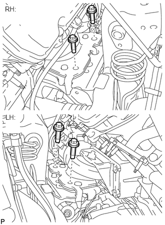
Remove the 4 engine mounting insulator bolts.
Lift the engine out from the vehicle slowly and carefully.
- NOTICE:
-
Make sure the engine is clear of all wiring, hoses and cables.
29.INSTALL ENGINE ON ENGINE STAND
Install the engine onto an engine stand with the bolts.
Remove the 2 bolts and 2 engine hangers.