B58 ENGINE CONTROL CAMSHAFT TIMING GEAR BOLT INSTALLATION
PROCEDURE

 135A0A
1.TEMPORARILY TIGHTEN EXHAUST CAMSHAFT TIMING GEAR BOLT ASSEMBLY
- HINT:
-
The figure shows the rear side of the engine.
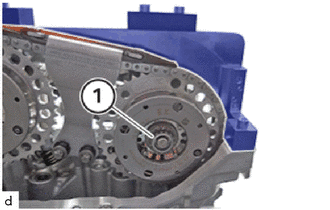
Guide in the exhaust camshaft timing gear bolt assembly (1) of the exhaust camshaft adjuster and install.
Hand-tighten the exhaust camshaft timing gear bolt assembly (1) of the exhaust camshaft adjuster.
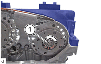
Release the exhaust camshaft timing gear bolt assembly (1) of the exhaust camshaft adjuster in the direction of arrow by 60°.
135A0
2.TEMPORARILY TIGHTEN INTAKE CAMSHAFT TIMING GEAR BOLT ASSEMBLY
- HINT:
-
The figure shows the rear side of the engine.
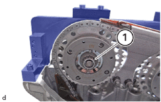
Guide in the intake camshaft timing gear bolt assembly (1) of the intake adjuster and install.
Hand-tighten the intake camshaft timing gear bolt assembly (1) of the intake adjuster.
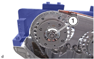
Release the intake camshaft timing gear bolt assembly (1) of the intake adjuster in the direction of arrow by 60 °.
3.REMOVE SST
4.ADJUST CAMSHAFT
13506
5.TEMPORARILY INSTALL CHAIN SUB-ASSEMBLY
135A0A
6.TIGHTEN EXHAUST CAMSHAFT TIMING GEAR BOLT ASSEMBLY
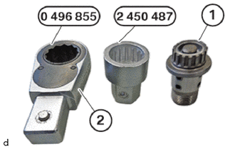
To tighten the exhaust camshaft timing gear bolt assembly (1) use the reversible ratchet (2) from the special tool 0 496855 with the special tool 2 450 487 .
- SST
- 09200-WA470
09200-WA800
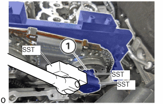
Install the exhaust camshaft timing gear bolt assembly of the exhaust camshaft adjuster (1) with the special tool 2 450 487.
- SST
- 09200-WA470
09200-WA800
09900-WA280
Tighten exhaust camshaft timing gear bolt assembly in 3 steps according to the table below.
- Torque:
1st 10 N*m (102 kgf*cm, 7 ft.*lbf) 2nd 30 N*m (306 kgf*cm, 22 ft.*lbf) 3rd 50 N*m (510 kgf*cm, 37 ft.*lbf)
- HINT:
-
Calculate the torque wrench reading when changing the fulcrum length of the torque wrench.
-
Click hereGeneral>INTRODUCTION>REPAIR INSTRUCTION>PRECAUTION
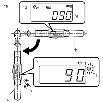
Using a digital angle torque wrench, tighten the exhaust camshaft timing gear bolt assembly an additional 35°.
- HINT:
-
 2.5,1.542 2.5,1.208 false 0.49,2.969 0.281,3.208 false 0.135,0.115 0.448,0.271 0.313,0.156 10 false *a 2.448,1.583 2.76,1.74 0.313,0.156 10 false *b 0.177,3.229 0.49,3.385 0.313,0.156 10 false *c 0.771,0.156 1.083,0.313 0.313,0.156 10 false *d 2.49,0.448 2.802,0.604 0.313,0.156 10 false *e 1.229,2 1.542,2.156 0.313,0.156 10 false *f 3.104,2.406 3.417,2.563 0.313,0.156 10 false *g 0.938,2.927 1.25,3.083 0.313,0.156 10 false *h
*a Example *b Before Tightening *c After Tightening *d Set Angle Display *e Setting the Specified Angle *f Tightening Angle Display *g LED Notification *h Buzzer Notification
- ·
When using the digital angle torque wrench, set the wrench to the specified tightening angle before use.
·When using the digital angle torque wrench, check the tightening angle display while performing the work.
·When tightening reaches the set angle, the buzzer will sound and a blue LED will illuminate.
135A0
7.TIGHTEN INTAKE CAMSHAFT TIMING GEAR BOLT ASSEMBLY
To tighten the intake camshaft timing gear bolt assembly (1) use the reversible ratchet (2) from the special tool 0 496855 with the special tool 2 450 487 .
- SST
- 09200-WA470
09200-WA800
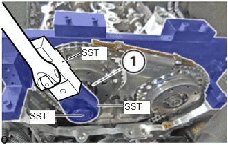
Install the intake camshaft timing gear bolt assembly of the intake camshaft adjuster (1) with the special tool 2 450 487.
- SST
- 09200-WA470
09200-WA800
09900-WA280
Tighten intake camshaft timing gear bolt assembly in 3 steps according to the table below.
- Torque:
1st 10 N*m (102 kgf*cm, 7 ft.*lbf) 2nd 30 N*m (306 kgf*cm, 22 ft.*lbf) 3rd 50 N*m (510 kgf*cm, 37 ft.*lbf)
- HINT:
-
Calculate the torque wrench reading when changing the fulcrum length of the torque wrench.
-
Click hereGeneral>INTRODUCTION>REPAIR INSTRUCTION>PRECAUTION
Using a digital angle torque wrench, tighten the intake camshaft timing gear bolt assembly an additional 35°.
- HINT:
-
2.5,1.542 2.5,1.208 false 0.49,2.969 0.281,3.208 false 0.135,0.115 0.448,0.271 0.313,0.156 10 false *a 2.448,1.583 2.76,1.74 0.313,0.156 10 false *b 0.177,3.229 0.49,3.385 0.313,0.156 10 false *c 0.771,0.156 1.083,0.313 0.313,0.156 10 false *d 2.49,0.448 2.802,0.604 0.313,0.156 10 false *e 1.229,2 1.542,2.156 0.313,0.156 10 false *f 3.104,2.406 3.417,2.563 0.313,0.156 10 false *g 0.938,2.927 1.25,3.083 0.313,0.156 10 false *h
*a Example *b Before Tightening *c After Tightening *d Set Angle Display *e Setting the Specified Angle *f Tightening Angle Display *g LED Notification *h Buzzer Notification
- ·
When using the digital angle torque wrench, set the wrench to the specified tightening angle before use.
·When using the digital angle torque wrench, check the tightening angle display while performing the work.
·When tightening reaches the set angle, the buzzer will sound and a blue LED will illuminate.
8.REMOVE SST
13540
9.INSTALL NO. 1 CHAIN TENSIONER ASSEMBLY
10.INSPECT CAMSHAFT TIMING
11201
11.INSTALL CYLINDER HEAD COVER SUB-ASSEMBLY
- NOTICE:
- ·
Improper routing of cables and wiring harnesses.
·Trapped, crushed or damaged cables may cause short circuits and malfunctions.
-Route all cables without abrasions, do not trap and crush.
- HINT:
-
Latch mechanisms, guides and mounting elements must not be damaged or missing.
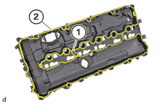
Replace cylinder head cover gasket (1) and (2).
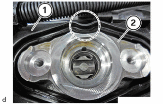
Ensure that the cylinder head cover sub-assembly (1) is installed in the marked area correctly on the high pressure pump bracket (2).
- NOTICE:
-
The cylinder head cover sub-assembly (1) must not touch the high pressure pump bracket (2) in the marked area.
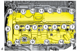
Position cylinder head cover sub-assembly.
Make sure that the cylinder head cover sub-assembly does not touch the high pressure pump bracket!
Tighten all E10 bolts in sequence (1) to (21).
- Torque:
- 8.0 N*m (82 kgf*cm, 71 in.*lbf)
Tighten all E10 bolts in a sequence from (1) to (21).
- Torque:
- 11 N*m (112 kgf*cm, 8 ft.*lbf)
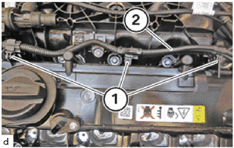
Thread in and install the engine wiring harness for engine wire (2).
Secure clamps (1).
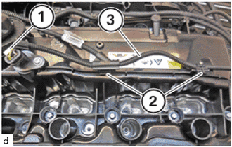
Thread in and install the engine wiring harness for No. 2 engine wire (3).
Secure clamps (2).
Connect connectors (1) and lock.
Make sure the connector (1) engages audibly.
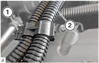
Insert and install the wiring harness section (2) for the injectors and ignition coils.
Secure the clamp (1).
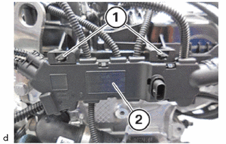
Thread in and install the engine wiring harness for No. 2 engine wire (2).
Ensure that the locks (1) engage audibly.
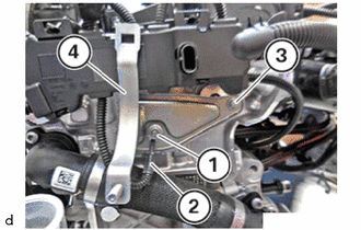
Insert and install the No. 1 electric water pump bracket sub-assembly (4).
Tighten down bolt (3).
- Torque:
- 8.0 N*m (82 kgf*cm, 71 in.*lbf)
Tighten down stud bolt.
- Torque:
- 8.0 N*m (82 kgf*cm, 71 in.*lbf)
Thread in No. 2 engine wire (2) and install.
Tighten nut (1).
- Torque:
- 8.0 N*m (82 kgf*cm, 71 in.*lbf)
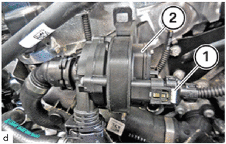
Thread in electric water pump assembly (2) and install.
Connect connectors (1) and lock.
Make sure the connector (1) engages audibly.
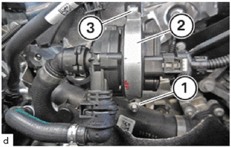
Thread in No. 2 electric engine water pump bracket sub-assembly (2) on holder (3) and install.
Tighten nut (1).
- Torque:
- 8.0 N*m (82 kgf*cm, 71 in.*lbf)
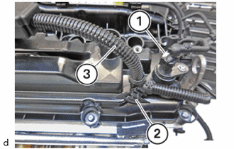
Thread in and install the engine wiring harness for No. 2 engine wire (3).
Secure clamps (2).
Connect connectors (1) and lock.
Make sure the connector (1) engages audibly.
- HINT:
-
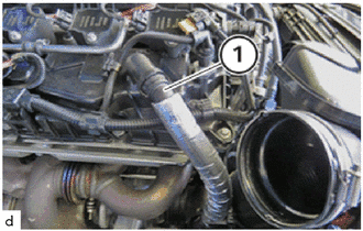
-
Latch mechanisms, guides and mounting elements must not be damaged or missing.
Connect ventilation hose (1) and lock.
Make sure that the engine ventilation line (1) engages audibly.
89467A
12.INSTALL WIDE RANGE AIR FUEL RATIO SENSOR
89465
13.INSTALL OXYGEN SENSOR
17801
14.INSTALL AIR CLEANER FILTER ELEMENT SUB-ASSEMBLY
15370J
15.INSTALL CAM TIMING OIL CONTROL SOLENOID ASSEMBLY
16. PREPARE INJECTORS FOR INSTALLATION
23815
17.INSTALL NO. 2 FUEL DELIVERY PIPE
23814B
18.INSTALL FUEL DELIVERY PIPE
19.INSTALL SPARK PLUG
55789B
20.INSTALL NO. 2 COWL TOP VENTILATOR LOUVER PROTECTOR
23100X
21.INSTALL FUEL (ENGINE ROOM SIDE) PUMP ASSEMBLY
51219
22.INSTALL FRONT SUSPENSION MEMBER LOWER PROTECTOR
23.REMOVE AND INSTALL HOOD SUPPORT ASSEMBLY
24.ADD ENGINE OIL
12180E
25.INSTALL OIL FILLER CAP ASSEMBLY
26. CHECK ENGINE OIL LEVEL