FA20 ENGINE CONTROL SFI SYSTEM P219A Bank 1 Air-Fuel Ratio Imbalance
DESCRIPTION
Refer to DTC P0300 (See page Engine / Hybrid System>FA20 (ENGINE CONTROL)>SFI SYSTEM>P0300).
Refer to DTC P2195 (See page Engine / Hybrid System>FA20 (ENGINE CONTROL)>SFI SYSTEM>P2195).
| DTC No. | DTC Detection Condition | Trouble Area |
|---|---|---|
| P219A | One of the following conditions is met (2 trip detection logic):
·
Air fuel ratio sensor signal fluctuates in air fuel ratio feedback control. ·
Crankshaft position sensor signal fluctuates in air fuel ratio feedback control. |
·
Fuel injector assembly (for port injection) ·
Fuel injector assembly (for direct injection) ·
Intake system ·
Gas leaks from exhaust system ·
Ignition system ·
Compression pressure ·
Air fuel ratio sensor ·
ECM |
MONITOR DESCRIPTION
- Fuel System Air Fuel Ratio Cylinder Imbalance Monitor
-
The ECM uses the air fuel ratio sensor and crankshaft position sensor to monitor the difference in air fuel ratios between the cylinders caused by differences in injection volumes between the cylinders, leakage in the intake or exhaust system, etc.
-
When the air fuel ratios of the cylinders are lean or rich with respect to each other, the ECM determines that a problem is present and stores a DTC.
- Air Fuel Ratio Sensor Monitoring Method
-
When the system detects a difference in air fuel ratios between the cylinders due to fluctuation in the air fuel ratio sensor output over 1 engine cycle (2 crankshaft revolutions), the system determines that there is a problem.
- Crankshaft Position Sensor Monitoring Method
-
The system monitors the engine speed variation and when the variation becomes large, the system determines that there is a difference in air fuel ratios between the cylinders, which it determines to be a problem.
CONFIRMATION DRIVING PATTERN
Connect the GTS to the DLC3.
Turn the ignition switch to ON and turn the GTS on.
Clear DTCs (even if no DTCs are stored, perform the clear DTC operation) (See page Engine / Hybrid System>FA20 (ENGINE CONTROL)>SFI SYSTEM>DTC CHECK / CLEAR).
Turn the ignition switch off and wait for at least 30 seconds.
Turn the ignition switch to ON and turn the GTS on.
Start the engine and warm it up until the engine coolant temperature reaches 75°C (167°F) or higher.
- HINT:
-
Check the engine coolant temperature is 20°C (68°F) or less at engine started.
Perform the following the confirmation driving pattern.
- CAUTION:
-
When performing the confirmation driving pattern, obey all speed limits and traffic laws.
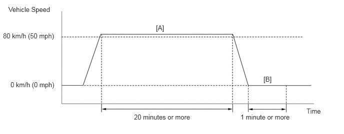
Drive the vehicle at 80 km/h (50 mph) or more for 20 minutes or more [A].
Stop the vehicle.
Idle the engine for 1 minute or more [B].
Enter the following menus: Powertrain / Engine / Trouble Codes.
Read pending DTCs.
- HINT:
- ·
If a pending DTC is output, the system is malfunctioning.
·If a pending DTC is not output, perform the following procedure.
Enter the following menus: Powertrain / Engine / Utility / All Readiness.
Input the DTC: P219A.
Check the DTC judgment result.
| GTS Display | Description |
|---|---|
| NORMAL | ·
DTC judgment completed ·
System normal |
| ABNORMAL | ·
DTC judgment completed ·
System abnormal |
| INCOMPLETE | ·
DTC judgment not completed ·
Perform driving pattern after confirming DTC enabling conditions |
| N/A | ·
Unable to perform DTC judgment ·
Number of DTCs which do not fulfill DTC preconditions has reached ECU memory limit |
- HINT:
- ·
If the judgment result shows NORMAL, the system is normal.
·If the judgment result shows ABNORMAL, the system has a malfunction.
If the test result is INCOMPLETE or N/A and no DTC is output, perform a universal trip and check for permanent DTCs (See page Engine / Hybrid System>FA20 (ENGINE CONTROL)>SFI SYSTEM>DTC CHECK / CLEAR).
- HINT:
- ·
If a permanent DTC is output, the system is malfunctioning.
·If no permanent DTC is output, the system is normal.
WIRING DIAGRAM
Refer to P0030 (See page Engine / Hybrid System>FA20 (ENGINE CONTROL)>SFI SYSTEM>P0030).
Refer to P0335 (See page Engine / Hybrid System>FA20 (ENGINE CONTROL)>SFI SYSTEM>P0335).
CAUTION / NOTICE / HINT
- HINT:
- ·
Read freeze frame data using the GTS. Freeze frame data records the engine condition when malfunctions are detected. When troubleshooting, freeze frame data can help determine if the vehicle was moving or stationary, if the engine was warmed up or not, if the air fuel ratio was lean or rich, and other data from the time the malfunction occurred.
·Bank 1 refers to the bank that includes the No. 1 cylinder*.
*: The No. 1 cylinder is the cylinder which is farthest from the transaxle.
·Bank 2 refers to the bank that does not include the No. 1 cylinder.
·Sensor 1 refers to the sensor closest to the engine assembly.
·Sensor 2 refers to the sensor farthest away from the engine assembly.
PROCEDURE
Connect the GTS to the DLC3.
Turn the ignition switch to ON.
Turn the GTS on.
Enter the following menus: Powertrain / Engine / Trouble Codes.
Read the DTCs.
| Result | Proceed to |
|---|---|
| DTC P219A is output | A |
| DTC P219A and other DTCs are output | B |
- HINT:
-
If any DTCs other than P219A are output, troubleshoot those DTCs first.
A
B
Connect the GTS to the DLC3.
Turn the ignition switch to ON.
Using the GTS, confirm the vehicle conditions recorded in the freeze frame data which were present when the DTC was stored (See page Engine / Hybrid System>FA20 (ENGINE CONTROL)>SFI SYSTEM>FREEZE FRAME DATA).
Vehicle Speed
Engine Speed
Calculate Load
Accelerator Idle Position
Short FT #1
Long FT #1
Cylinder #1 Misfire Count to Cylinder #4 Misfire Count
- HINT:
-
When the sum of Short FT and Long FT is positive, the engine is running lean, and when the sum is negative, the engine is running rich.
| DTC stored during idling | It is possible to conclude that the problem was detected due to a "lean imbalance" (detected using crankshaft speed variation). |
| DTC stored while vehicle being driven | It is possible to conclude that the problem was detected due to a "rich imbalance" (detected using the air fuel ratio sensor). |
NEXT
Connect the GTS to the DLC3.
Start the engine.
Turn the GTS on.
Warm up the engine.
- HINT:
-
The A/C switch and all accessory switches should be off and the shift lever should be in P, N or neutral.
Enter the following menus: Powertrain / Engine / Active Test / Control the Injection Volume / Cylinder #1 to #4 Misfire Count.
- HINT:
-
When the "Control the Injection Volume" Active Test is selected (injection volume is 0%), if a misfire count increases, proceed to step 6 (Check Intake System).
Perform the Control the Injection Volume operation with the engine idling.
Check the misfire counts ("Cylinder #1 Misfire Count" to "Cylinder #4 Misfire Count") while decreasing the injection volume in 5% increments.
- NOTICE:
-
Do not decrease the injection volume by higher than 20%.
- Result:
The cylinder whose misfire count has not increased can be assumed to be running rich. Therefore, perform inspections while focusing on that cylinder.
NEXT
Check for exhaust gas leaks.
- OK:
No gas leaks.
OK
NG
Check the intake system for vacuum leaks (See page Engine / Hybrid System>FA20 INTAKE / EXHAUST>INTAKE SYSTEM>ON-VEHICLE INSPECTION).
- OK:
No leaks in the intake system.
OK
NG
Inspect the spark plug of the cylinder causing the imbalance (See page Engine / Hybrid System>FA20 (ENGINE CONTROL)>IGNITION SYSTEM>ON-VEHICLE INSPECTION).
OK
NG
Perform a spark test (See page Engine / Hybrid System>FA20 (ENGINE CONTROL)>IGNITION SYSTEM>ON-VEHICLE INSPECTION).
- HINT:
-
If the result of the spark test is normal, proceed to the next step.
NEXT
Measure the cylinder compression pressure of the misfiring cylinder (See page Engine / Hybrid System>FA20 (ENGINE MECHANICAL)>ENGINE>ON-VEHICLE INSPECTION).
OK
NG
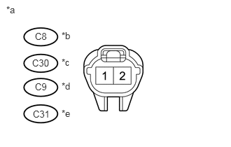
Disconnect the fuel injector assembly (for port injection) connector.
Turn the ignition switch to ON.
Measure the voltage according to the value(s) in the table below.
- Standard Voltage:
Tester Connection Condition Specified Condition C8-1 - Body ground Ignition switch ON 11 to 14 V C30-1 - Body ground Ignition switch ON 11 to 14 V C9-1 - Body ground Ignition switch ON 11 to 14 V C31-1 - Body ground Ignition switch ON 11 to 14 V
| *a | Front view of wire harness connector
(to Fuel Injector Assembly) |
| *b | No. 1 cylinder |
| *c | No. 2 cylinder |
| *d | No. 3 cylinder |
| *e | No. 4 cylinder |
OK
NG
Check the harness and connector of fuel injector assembly (for port injection) (See page Engine / Hybrid System>FA20 (ENGINE CONTROL)>SFI SYSTEM>P0201).
Check the harness and connector of fuel injector assembly (for direct injection) (See page Engine / Hybrid System>FA20 (ENGINE CONTROL)>SFI SYSTEM>P062D).
OK
NG
Check the fuel injector assembly (for port injection) [whether fuel volume is high or low, and whether injection pattern is poor] (See page Engine / Hybrid System>FA20 FUEL>FUEL INJECTOR(for Port Injection)>INSPECTION).
Check the fuel injector assembly (for direct injection) [whether fuel volume is high or low, and whether injection pattern is poor] (See page Engine / Hybrid System>FA20 FUEL>FUEL INJECTOR(for Direct Injection)>INSPECTION).
- Result:
Result Proceed to OK A Fuel injector assembly (for port injection) is NG. B Fuel injector assembly (for direct injection) is NG. C
A
B
C
If the cause of the problem has not been found even after performing the troubleshooting procedure, perform the inspection below.
Check the intake valve for deposits.
- HINT:
-
As the DTC may have been stored due to deposits on the intake valve, remove the cylinder head and check the intake valve.
NEXT
Connect the GTS to the DLC3.
Turn the ignition switch to ON.
Turn the GTS on.
Clear the DTCs (See page Engine / Hybrid System>FA20 (ENGINE CONTROL)>SFI SYSTEM>DTC CHECK / CLEAR).
Turn the ignition switch off and wait for at least 30 seconds.
Turn the ignition switch to ON.
Turn the GTS on.
Drive the vehicle in accordance with the driving pattern described in Confirmation Driving Pattern.
Enter the following menus: Powertrain / Engine / Trouble Codes.
Check for DTCs.
- Result:
P219A is not output.
NEXT