HEATING / AIR CONDITIONING AIR CONDITIONING UNIT(for LHD) INSTALLATION
CAUTION / NOTICE / HINT
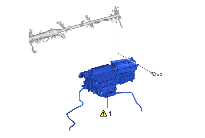
| Procedure | Part Name Code | 
|

|

|
|
| 1 | TEMPORARILY TIGHTEN AIR CONDITIONER UNIT ASSEMBLY | - | ( ) |
- | - |
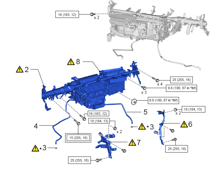
| Procedure | Part Name Code |
|
|
|
|
|---|---|---|---|---|---|
| 2 | INSTRUMENT PANEL REINFORCEMENT ASSEMBLY WITH AIR CONDITIONING UNIT ASSEMBLY | - | ()
|
- | - |
| 3 | COOLER UNIT DRAIN HOSE GROMMET | 88539G | ()
|
- | - |
| 4 | NO. 4 COOLER UNIT DRAIN HOSE | 88539N | - | - | - |
| 5 | NO. 3 COOLER UNIT DRAIN HOSE | 88539E | - | - | - |
| 6 | NO. 2 INSTRUMENT PANEL BRACE SUB-ASSEMBLY | 55307C | ()
|
- | - |
| 7 | NO. 1 INSTRUMENT PANEL BRACE SUB-ASSEMBLY | 55306A | ()
|
- | - |
| 8 | TIGHTEN AIR CONDITIONER UNIT ASSEMBLY | - | ()
|
- | - |

|
Tightening torque for "Major areas involving basic vehicle performance such as moving/turning/stopping": N*m (kgf*cm, ft.*lbf) | 
|
N*m (kgf*cm, ft.*lbf): Specified torque |
| ● | Non-reusable part | - | - |
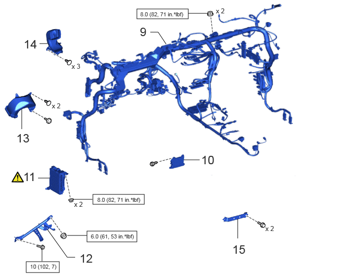
| Procedure | Part Name Code |
|
|
|
|
|---|---|---|---|---|---|
| 9 | INSTRUMENT PANEL WIRE | 82141 | - | - | - |
| 10 | AIR CONDITIONING AMPLIFIER ASSEMBLY WITH HEATER BRACKET | - | - | - | - |
| 11 | DRIVER SIDE JUNCTION BLOCK ASSEMBLY WITH MAIN BODY ECU | - | ()
|
- | - |
| 12 | NO. 3 INSTRUMENT PANEL TO COWL BRACE SUB-ASSEMBLY | 55308B | - | - | - |
| 13 | NO. 1 HEATER TO REGISTER DUCT | 55843A | - | - | - |
| 14 | NO. 3 HEATER TO REGISTER DUCT | 55845A | - | - | - |
| 15 | NO. 1 INSTRUMENT PANEL SHIFT MOUNTING BRACKET | 55381D | - | - | - |
|
|
N*m (kgf*cm, ft.*lbf): Specified torque | - | - |
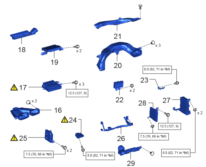
| Procedure | Part Name Code |
|
|
|
|
|---|---|---|---|---|---|
| 16 | NO. 4 HEATER TO REGISTER DUCT | 55846A | - | - | - |
| 17 | TELEMATICS TRANSCEIVER WITH BRACKET | - | ()
|
- | - |
| 18 | LOWER DEFROSTER NOZZLE ASSEMBLY | 55990B | - | - | - |
| 19 | NAVIGATION ECU ASSEMBLY WITH BRACKET | - | - | - | - |
| 20 | NO. 2 SIDE DEFROSTER NOZZLE DUCT | 55972C | - | - | - |
| 21 | NO. 5 HEATER TO REGISTER DUCT | 55847B | - | - | - |
| 22 | STEREO COMPONENT EQUALIZER ASSEMBLY | 86240A | - | - | - |
| 23 | WIRING HARNESS CLAMP BRACKET | 82715 | - | - | - |
| 24 | NO. 1 SEMICONDUCTOR POWER INTEGRATION ECU | 82644A | ()
|
- | - |
| 25 | SHIFT CONTROL ECU | 894C1 | ()
|
- | - |
| 26 | FRONT COMPARTMENT WIRE MAIN | 82111C | - | - | - |
| 27 | PASSENGER SIDE JUNCTION BLOCK ASSEMBLY | 82730D | - | - | - |
| 28 | EV CONTROL ECU WITH EV CONTROL ECU BRACKET | - | - | - | - |
| 29 | NO. 3 AIR DUCT SUB-ASSEMBLY | 87201F | - | - | - |
|
|
N*m (kgf*cm, ft.*lbf): Specified torque | - | - |
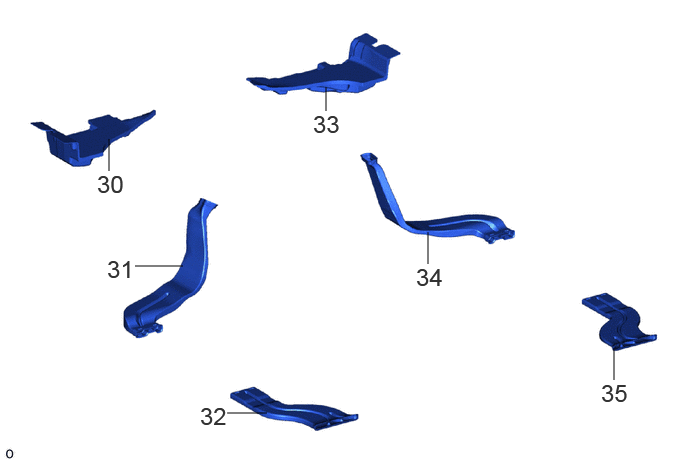
| Procedure | Part Name Code |
|
|
|
|
|---|---|---|---|---|---|
| 30 | FRONT FLOOR MAT LH | 58512B | - | - | - |
| 31 | REAR NO. 3 AIR DUCT | 87212G | - | - | - |
| 32 | REAR NO. 4 AIR DUCT | 87212H | - | - | - |
| 33 | FRONT FLOOR MAT RH | 58511H | - | - | - |
| 34 | REAR NO. 1 AIR DUCT | 87212 | - | - | - |
| 35 | REAR NO. 2 AIR DUCT | 87212F | - | - | - |
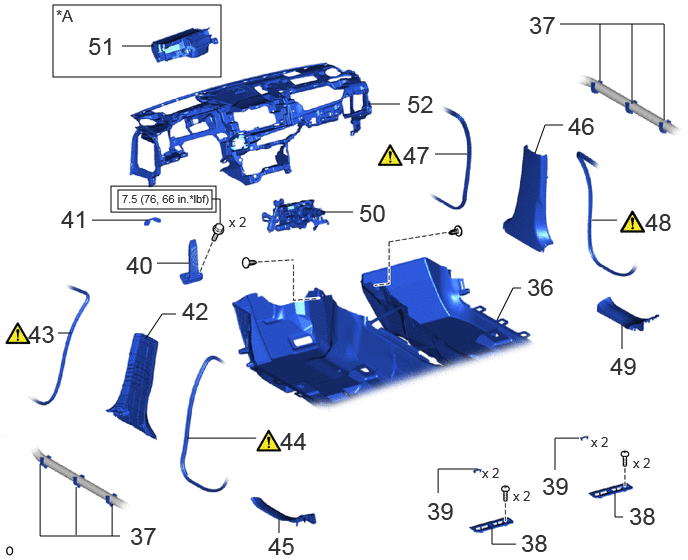
| Procedure | Part Name Code |
|
|
|
|
|---|---|---|---|---|---|
| 36 | FRONT FLOOR FRONT CARPET ASSEMBLY | 58510C | - | - | - |
| 37 | NO. 2 FLOOR CARPET HOOK | 58521C | - | - | - |
| 38 | REAR NO. 5 AIR DUCT | 87212J | - | - | - |
| 39 | AIR DUCT PLUG | 87217B | - | - | - |
| 40 | ACCELERATOR PEDAL ASSEMBLY | 78010F | - | - | - |
| 41 | ACCELERATOR PEDAL PAD | 78118 | - | - | - |
| 42 | LOWER CENTER PILLAR GARNISH LH | 62414A | - | - | - |
| 43 | FRONT DOOR OPENING TRIM WEATHERSTRIP LH | 62312B | ()
|
- | - |
| 44 | REAR DOOR OPENING TRIM WEATHERSTRIP LH | 62332A | ()
|
- | - |
| 45 | REAR DOOR SCUFF PLATE INSIDE LH | 67918F | - | - | - |
| 46 | LOWER CENTER PILLAR GARNISH RH | 62413A | - | - | - |
| 47 | FRONT DOOR OPENING TRIM WEATHERSTRIP RH | 62311B | ()
|
- | - |
| 48 | REAR DOOR OPENING TRIM WEATHERSTRIP RH | 62331A | ()
|
- | - |
| 49 | REAR DOOR SCUFF PLATE INSIDE RH | 67917F | - | - | - |
| 50 | STEERING COLUMN ASSEMBLY | - | - | - | - |
| 51 | METER MIRROR SUB-ASSEMBLY | 83108 | - | - | - |
| 52 | INSTRUMENT PANEL SAFETY PAD | - | - | - | - |
| *A | w/ Headup Display | - | - |
|
|
Tightening torque for "Major areas involving basic vehicle performance such as moving/turning/stopping": N*m (kgf*cm, ft.*lbf) | - | - |
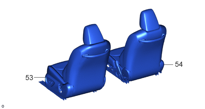
| Procedure | Part Name Code |
|
|
|
|
|---|---|---|---|---|---|
| 53 | FRONT SEAT ASSEMBLY LH | - | - | - | - |
| 54 | FRONT SEAT ASSEMBLY RH | - | - | - | - |
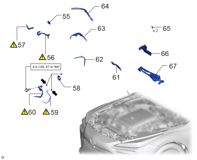
| Procedure | Part Name Code |
|
|
|
|
|---|---|---|---|---|---|
| 55 | GROMMET | 88898D | - | - | - |
| 56 | WATER HOSE SUB-ASSEMBLY C | 87209C | ()
|
- | - |
| 57 | WATER HOSE SUB-ASSEMBLY E | 87209E | ()
|
- | - |
| 58 | COOLER PIPE GROMMET | 88897K | - | - | - |
| 59 | NO. 1 LIQUID TUBE | 88G16M | ()
|
- | - |
| 60 | SUCTION HOSE SUB-ASSEMBLY A | 88704A | ()
|
- | - |
| 61 | FC CONVERTER POWER OUTLET CABLE (INVERTER WITH CONVERTER ASSEMBLY) | G9200A | - | - | - |
| 62 | FC AIR COMPRESSOR MOTOR CABLE ASSEMBLY | 17A90 | - | - | - |
| 63 | FLOOR UNDER WIRE | 821H1 | - | - | - |
| 64 | NO. 1 BATTERY PACK WIRE | 821H3A | - | - | - |
| 65 | HOLE PLUG | - | - | - | - |
| 66 | COWL VENTILATOR SPLASH SHIELD LH | 55752A | - | - | - |
| 67 | FRONT WIPER MOTOR AND LINK | - | - | - | - |
|
|
N*m (kgf*cm, ft.*lbf): Specified torque | ● | Non-reusable part |

|
Compressor oil ND-OIL 11 or equivalent | - | - |
| Procedure | Part Name Code |
|
|
|
|
|---|---|---|---|---|---|
| 68 | ADD COOLANT (TOYOTA GENUINE FC STACK COOLANT (Pre-mixed)) | - | - | ()
|
- |
| 69 | CHARGE AIR CONDITIONING SYSTEM WITH REFRIGERANT | - | ()
|
- | - |
| 70 | INSPECT FOR COOLANT (TOYOTA GENUINE FC STACK COOLANT (Pre-mixed)) LEAK | - | ()
|
- | - |
| 71 | WARM UP COMPRESSOR | - | ()
|
- | - |
| 72 | INSPECT FOR REFRIGERANT LEAK | - | ()
|
- | - |
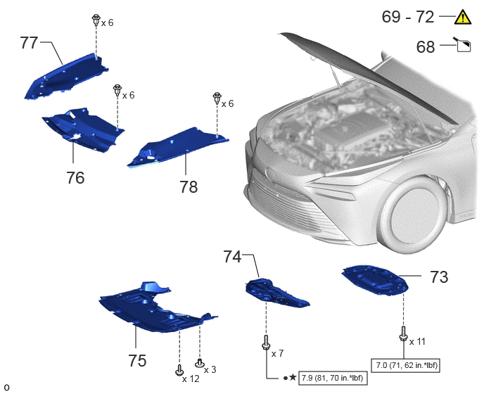
| 73 | FRONT COMPARTMEMT UNDER COVER ASSEMBLY | 51420A | - | - | - |
| 74 | FRONT LOWER SUSPENSION MEMBER PROTECTOR | 51219 | - | - | - |
| 75 | FRONT COMPARTMENT UNDER COVER | 51441N | - | - | - |
| 76 | LOWER RADIATOR AIR DEFLECTOR | 53295 | - | - | - |
| 77 | UPPER RADIATOR SUPPORT SEAL | 53292A | - | - | - |
| 78 | RADIATOR COVER PLATE | 53291B | - | - | - |
|
|
N*m (kgf*cm, ft.*lbf): Specified torque | ● | Non-reusable part |
| ★ | Precoated part | - | - |
CAUTION / NOTICE / HINT
- HINT:
-
A bolt without a torque specification is shown in the standard bolt chart.
-
Click hereGeneral>SPECIFICATIONS>STANDARD BOLT>SPECIFIED TORQUE FOR STANDARD BOLTS
PROCEDURE

 1.TEMPORARILY TIGHTEN AIR CONDITIONER UNIT ASSEMBLY
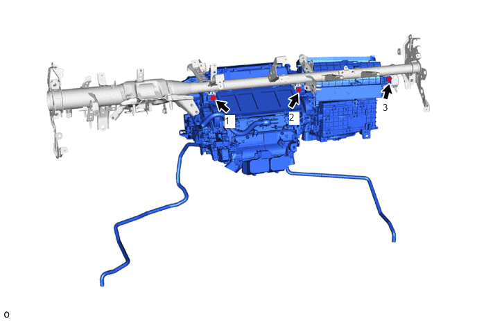
Temporarily tighten the air conditioning unit assembly with the 3 bolts in the order shown in the illustration.
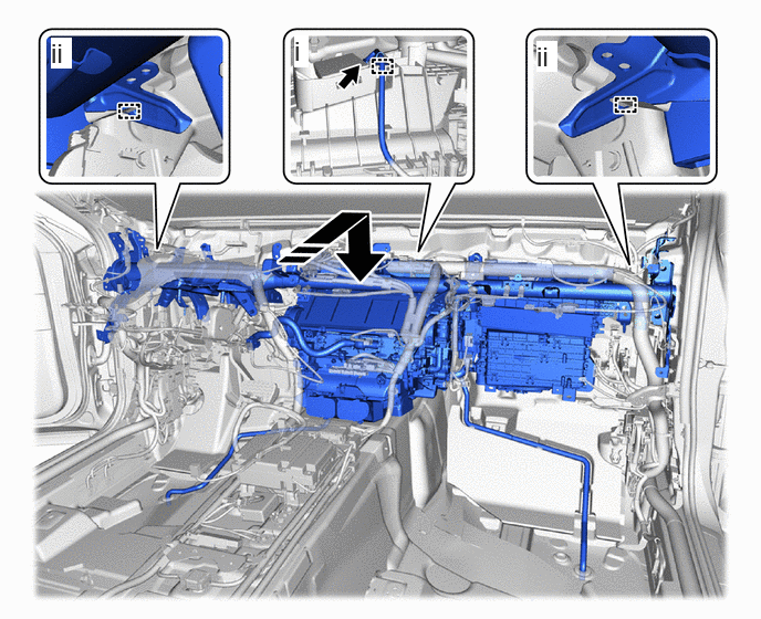
2.INSTALL INSTRUMENT PANEL REINFORCEMENT ASSEMBLY WITH AIR CONDITIONING UNIT ASSEMBLY
|
|
|

|
Install to Guide by Inserting to the End | - | - |
Connect the connector and attach the clamp.
Install the instrument panel reinforcement assembly with air conditioning unit assembly to the guide as shown in the illustration.
- NOTICE:
- ·
Be careful not to damage the internal components of the instrument panel reinforcement assembly and air conditioning unit assembly on the glass etc. Only perform installation after first taking the appropriate actions.
·Make sure that both parts are securely installed to the guide.
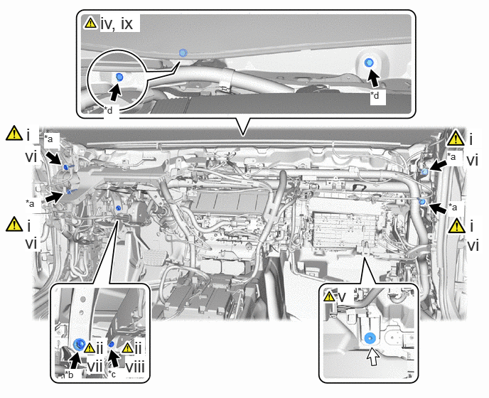
| *a | Bolt (A) | *b | Bolt (B) |
| *c | Bolt (C) | *d | Bolt (D) |
|
|
Bolt | 
|
Nut |
Temporarily install the 4 bolts (A).
Temporarily install the bolt (C).
Temporarily install the bolt (B).
Using a universal socket wrench 12 mm, temporarily install the 2 bolts (D).
Temporarily install the nut.
Tighten the 4 bolts (A).
- Torque:
- 25 N*m (255 kgf*cm, 18 ft.*lbf)
Tighten the bolt (C).
- Torque:
- 16 N*m (163 kgf*cm, 12 ft.*lbf)
Tighten the bolt (B).
- Torque:
- 15 N*m (153 kgf*cm, 11 ft.*lbf)
Using a universal socket wrench 12 mm, tighten the 2 bolts (D).
- Torque:
- 16 N*m (163 kgf*cm, 12 ft.*lbf)
88539G
3.INSTALL COOLER UNIT DRAIN HOSE GROMMET
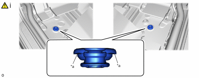
| *a | Lip | - | - |
Press the entire upper surface of the rib on a new cooler unit drain hose grommet, and fit the entire circumference of the lip to the hole.
- NOTICE:
- ·
If the drain cooler hose is disconnected from the cooler unit drain hose grommet, make sure to replace the cooler unit drain hose grommet with a new one. Failure to do so may lead to water ingress.
·Make sure that the entire lip of the cooler unit drain hose grommet is securely engaged to the vehicle body.
88539N
4.INSTALL NO. 4 COOLER UNIT DRAIN HOSE
88539E
5.INSTALL NO. 3 COOLER UNIT DRAIN HOSE
55307C
6.INSTALL NO. 2 INSTRUMENT PANEL BRACE SUB-ASSEMBLY
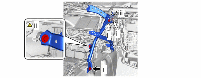
|
|
Bolt |
|
Nut |

|
Screw | - | - |
Install the No. 2 instrument panel brace sub-assembly with the 2 nuts and bolt.
- Torque:
- Bolt : 25 N*m (255 kgf*cm, 18 ft.*lbf)
- Nut : 18 N*m (184 kgf*cm, 13 ft.*lbf)
Temporarily install the screw.
Attach the clamp.
55306A
7.INSTALL NO. 1 INSTRUMENT PANEL BRACE SUB-ASSEMBLY
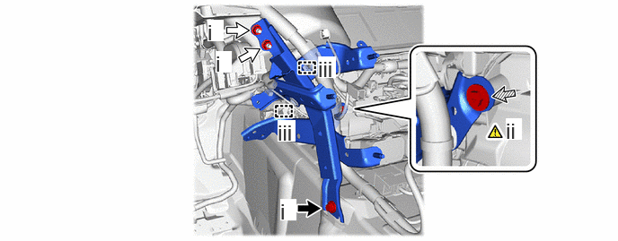
|
|
Bolt |
|
Nut |
|
|
Screw | - | - |
Install the No. 1 instrument panel brace sub-assembly with the 2 nuts and bolt.
- Torque:
- Bolt : 25 N*m (255 kgf*cm, 18 ft.*lbf)
- Nut : 18 N*m (184 kgf*cm, 13 ft.*lbf)
Temporarily install the screw.
Attach the clamp.
8.TIGHTEN AIR CONDITIONER UNIT ASSEMBLY
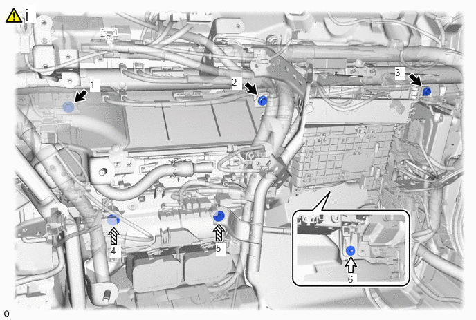
|
|
Bolt |
|
Nut |
|
|
Screw | - | - |
Tighten the 3 bolts, 2 screws and nut in the order shown in the illustration.
- Torque:
- Bolt : 9.8 N*m (100 kgf*cm, 87 in.*lbf)
- Nut : 9.8 N*m (100 kgf*cm, 87 in.*lbf)
82141
9.CONNECT INSTRUMENT PANEL WIRE
- Torque:
- 8.0 N*m (82 kgf*cm, 71 in.*lbf)
10.INSTALL AIR CONDITIONING AMPLIFIER ASSEMBLY WITH HEATER BRACKET
11.INSTALL DRIVER SIDE JUNCTION BLOCK ASSEMBLY WITH MAIN BODY ECU
|
|
Click here()
|
55308B
12.INSTALL NO. 3 INSTRUMENT PANEL TO COWL BRACE SUB-ASSEMBLY
- Torque:
- Bolt : 10 N*m (102 kgf*cm, 7 ft.*lbf)
- Nut : 6.0 N*m (61 kgf*cm, 53 in.*lbf)
55843A
13.INSTALL NO. 1 HEATER TO REGISTER DUCT
55845A
14.INSTALL NO. 3 HEATER TO REGISTER DUCT
55381D
15.INSTALL NO. 1 INSTRUMENT PANEL SHIFT MOUNTING BRACKET
55846A
16.INSTALL NO. 4 HEATER TO REGISTER DUCT
17.INSTALL TELEMATICS TRANSCEIVER WITH BRACKET
|
|
Click here()
|
55990B
18.INSTALL LOWER DEFROSTER NOZZLE ASSEMBLY
19.INSTALL NAVIGATION ECU ASSEMBLY WITH BRACKET
55972C
20.INSTALL NO. 2 SIDE DEFROSTER NOZZLE DUCT
55847B
21.INSTALL NO. 5 HEATER TO REGISTER DUCT
86240A
22.INSTALL STEREO COMPONENT EQUALIZER ASSEMBLY
82715
23.INSTALL WIRING HARNESS CLAMP BRACKET
- Torque:
- 8.0 N*m (82 kgf*cm, 71 in.*lbf)
82644A
24.INSTALL NO. 1 SEMICONDUCTOR POWER INTEGRATION ECU
|
|
Click here()
|
894C1
25.INSTALL SHIFT CONTROL ECU
|
|
Click here()
|
82111C
26.CONNECT FRONT COMPARTMENT WIRE MAIN
82730D
27.INSTALL PASSENGER SIDE JUNCTION BLOCK ASSEMBLY
- Torque:
- 8.0 N*m (82 kgf*cm, 71 in.*lbf)
28.INSTALL EV CONTROL ECU WITH EV CONTROL ECU BRACKET
87201F
29.INSTALL NO. 3 AIR DUCT SUB-ASSEMBLY
58512B
30.INSTALL FRONT FLOOR MAT LH
87212G
31.INSTALL REAR NO. 3 AIR DUCT
87212H
32.INSTALL REAR NO. 4 AIR DUCT
58511H
33.INSTALL FRONT FLOOR MAT RH
87212
34.INSTALL REAR NO. 1 AIR DUCT
87212F
35.INSTALL REAR NO. 2 AIR DUCT
58510C
36.INSTALL FRONT FLOOR FRONT CARPET ASSEMBLY
58521C
37.INSTALL NO. 2 FLOOR CARPET HOOK
87212J
38.INSTALL REAR NO. 5 AIR DUCT
87217B
39.INSTALL AIR DUCT PLUG
78010F
40.INSTALL ACCELERATOR PEDAL ASSEMBLY
78118
41.INSTALL ACCELERATOR PEDAL PAD
62414A
42.INSTALL LOWER CENTER PILLAR GARNISH LH
62312B
43.INSTALL FRONT DOOR OPENING TRIM WEATHERSTRIP LH
|
|
Click here()
|
62332A
44.INSTALL REAR DOOR OPENING TRIM WEATHERSTRIP LH
|
|
Click here()
|
67918F
45.INSTALL REAR DOOR SCUFF PLATE INSIDE LH
62413A
46.INSTALL LOWER CENTER PILLAR GARNISH RH
62311B
47.INSTALL FRONT DOOR OPENING TRIM WEATHERSTRIP RH
Use the same procedure described for the LH side.
62331A
48.INSTALL REAR DOOR OPENING TRIM WEATHERSTRIP RH
Use the same procedure described for the LH side.
67917F
49.INSTALL REAR DOOR SCUFF PLATE INSIDE RH
45250
50.INSTALL STEERING COLUMN ASSEMBLY
for Manual Tilt and Manual Telescopic Steering Column:
for Power Tilt and Power Telescopic Steering Column:
83108
51.INSTALL METER MIRROR SUB-ASSEMBLY (w/ Headup Display)
52.INSTALL INSTRUMENT PANEL SAFETY PAD
53.INSTALL FRONT SEAT ASSEMBLY LH
54.INSTALL FRONT SEAT ASSEMBLY RH
Use the same procedure described for the LH side.
88898D
55.INSTALL GROMMET
87209C
56.CONNECT WATER HOSE SUB-ASSEMBLY C
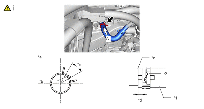
| *1 | Water Hose Sub-assembly C | *2 | Hose Clip |
| *a | View A | *b | Marking (Green) |
| *c | Hose Clip Installation Angle (30 to 60° From Above the Vehicle) | *d | Hose Clip Installation Range (3 to 7 mm (0.119 to 0.276 in.)) |
| *e | Stopper | - | - |
Connect the water hose sub-assembly C with its marking facing upward and install the hose clip within the range shown in the illustration.
- NOTICE:
-
Do not apply excessive force to the water hose sub-assembly c.
87209E
57.CONNECT WATER HOSE SUB-ASSEMBLY E
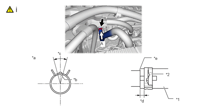
| *1 | Water Hose Sub-assembly E | *2 | Hose Clip |
| *a | View A | *b | Marking (Blue) |
| *c | Hose Clip Installation Angle (15° From Above the Vehicle) | *d | Hose Clip Installation Range (3 to 7 mm (0.119 to 0.276 in.)) |
| *e | Stopper | - | - |
Connect the water hose sub-assembly E with its marking facing upward and install the hose clip within the range shown in the illustration.
- NOTICE:
-
Do not apply excessive force to the water hose sub-assembly E.
88897K
58.INSTALL COOLER PIPE GROMMET
88G16M
59.CONNECT NO. 1 LIQUID TUBE
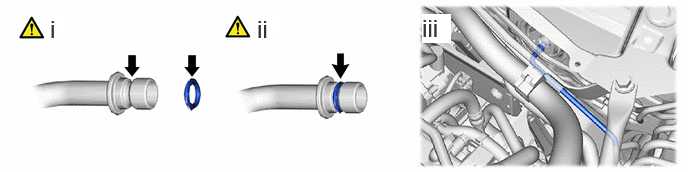
Sufficiently apply compressor oil to a new O-ring and the fitting surface of the No. 1 liquid tube.
- Compressor Oil:
ND-OIL 11 or equivalent
Install the O-ring to the No. 1 liquid tube.
- NOTICE:
-
Keep the O-ring and O-ring fitting surface free of foreign matter.
Connect the No. 1 liquid tube.
88704A
60.CONNECT SUCTION HOSE SUB-ASSEMBLY A
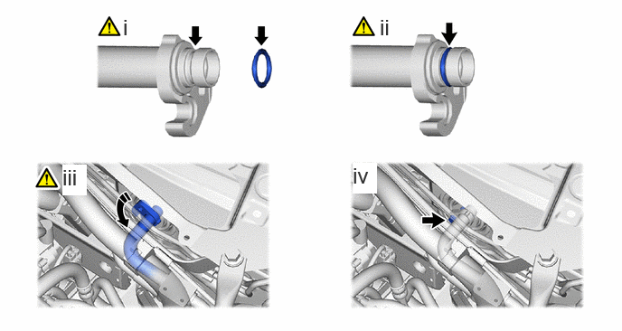
|
|
Install in this Direction | - | - |
Sufficiently apply compressor oil to a new O-rings and the fitting surface of the suction hose sub-assembly A.
- Compressor Oil:
ND-OIL 11 or equivalent
Install the O-ring to the suction hose sub-assembly A.
- NOTICE:
-
Keep the O-ring and O-ring fitting surface free of foreign matter.
Rotate the 1-point tightening plate as shown in the illustration.
Install the bolt.
- Torque:
- 9.8 N*m (100 kgf*cm, 87 in.*lbf)
G9200A
61.CONNECT FC CONVERTER POWER OUTLET CABLE (INVERTER WITH CONVERTER ASSEMBLY)
17A90
62.CONNECT FC AIR COMPRESSOR MOTOR CABLE ASSEMBLY
821H1
63.CONNECT FLOOR UNDER WIRE
821H3A
64.CONNECT NO. 1 BATTERY PACK WIRE
65.INSTALL HOLE PLUG
55752A
66.INSTALL COWL VENTILATOR SPLASH SHIELD LH
67.INSTALL FRONT WIPER MOTOR AND LINK
68.ADD COOLANT (TOYOTA GENUINE FC STACK COOLANT (Pre-mixed))
69.CHARGE AIR CONDITIONING SYSTEM WITH REFRIGERANT
for HFC-134a(R134a):
Click hereVehicle Interior>HEATING / AIR CONDITIONING>REFRIGERANT (for HFC-134a(R134a))>REPLACEMENT
for HFO-1234yf(R1234yf):
Click hereVehicle Interior>HEATING / AIR CONDITIONING>REFRIGERANT (for HFO-1234yf(R1234yf))>REPLACEMENT
70.INSPECT FOR COOLANT (TOYOTA GENUINE FC STACK COOLANT (Pre-mixed)) LEAK
71.WARM UP COMPRESSOR
for HFC-134a(R134a):
Click hereVehicle Interior>HEATING / AIR CONDITIONING>REFRIGERANT (for HFC-134a(R134a))>REPLACEMENT
for HFO-1234yf(R1234yf):
Click hereVehicle Interior>HEATING / AIR CONDITIONING>REFRIGERANT (for HFO-1234yf(R1234yf))>REPLACEMENT
72.INSPECT FOR REFRIGERANT LEAK
for HFC-134a(R134a):
Click hereVehicle Interior>HEATING / AIR CONDITIONING>REFRIGERANT (for HFC-134a(R134a))>REPLACEMENT
for HFO-1234yf(R1234yf):
Click hereVehicle Interior>HEATING / AIR CONDITIONING>REFRIGERANT (for HFO-1234yf(R1234yf))>REPLACEMENT
51420A
73.INSTALL FRONT COMPARTMEMT UNDER COVER ASSEMBLY
51219
74.INSTALL FRONT LOWER SUSPENSION MEMBER PROTECTOR
51441N
75.INSTALL FRONT COMPARTMENT UNDER COVER
53295
76.INSTALL LOWER RADIATOR AIR DEFLECTOR
53292A
77.INSTALL UPPER RADIATOR SUPPORT SEAL
53291B
78.INSTALL RADIATOR COVER PLATE