2WW ENGINE MECHANICAL ENGINE UNIT REASSEMBLY
CAUTION / NOTICE / HINT
- NOTICE:
- ·
Always be sure to check the tightening torque.
·If the pressure lines are leaking after installation, they must be replaced.
·Do not overtighten the pressure lines.
·All pressure lines may only be reused 3 times. After the 3rd time, they must be replaced.
PROCEDURE

 15709
1.INSTALL NO. 2 OIL NOZZLE SUB-ASSEMBLY
Using an E8 "TORX" socket wrench, install the No. 2 oil nozzle sub-assembly with the bolt.
- Torque:
- : 10 N*m (102 kgf*cm, 7 ft.*lbf)
13613
2.INSTALL INJECTION PUMP DRIVE GEAR
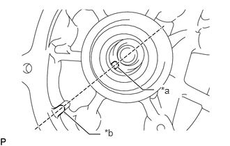
| *a | Cutout |
| *b | Protrusion |
Align the cutout of the fuel supply pump assembly with the protrusion of the cylinder block and temporarily install the fuel supply pump with the 2 bolts.
Set the chain sub-assembly to the crankshaft.
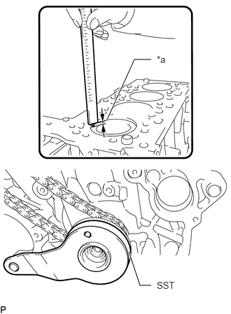
| *a | 0.5 to 1.0 mm (0.0197 to 0.0394 in.) |
Install SST by rotating the crankshaft as shown in the illustration.
- SST:
PZ4TB-04964-42
- HINT:
-
The No. 1 piston position is 0.5 to 1.0 mm (0.0197 to 0.0394 in.) lower than the top of the cylinder block.
Install the injection pump drive gear with the chain sub-assembly.
Install the fuel supply pump assembly with the 2 bolts.
- Torque:
- : 19 N*m (194 kgf*cm, 14 ft.*lbf)
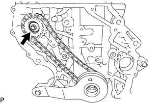
Install the central bolt to the injection pump drive gear.
- Torque:
- : 65 N*m (663 kgf*cm, 48 ft.*lbf)
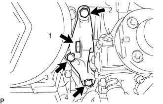
Temporarily install the fuel supply pump assembly support with the 4 bolts by hand in the sequence shown in the illustration.
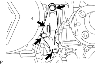
Tighten the 4 bolts in the sequence shown in the illustration.
- Torque:
- : 19 N*m (194 kgf*cm, 14 ft.*lbf)
13566B
3.INSTALL TIMING CHAIN GUIDE
Using a T45 "TORX" socket wrench, install the timing chain guide with the 2 bolts.
- Torque:
- : 20 N*m (204 kgf*cm, 15 ft.*lbf)
13591
4.INSTALL TIMING CHAIN TENSION ARM
Using a T45 "TORX" socket wrench, install the timing chain tension arm with the bolt.
- Torque:
- : 20 N*m (204 kgf*cm, 15 ft.*lbf)
13540
5.INSTALL NO. 1 CHAIN TENSIONER ASSEMBLY
Using an E8 "TORX" socket wrench, install the No. 1 chain tensioner assembly with the 2 bolts.
- Torque:
- : 10 N*m (102 kgf*cm, 7 ft.*lbf)
Remove the 3.0 mm hexagon wrench from the No. 1 chain tensioner assembly.
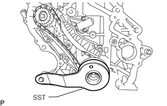
Remove SST.
- SST:
PZ4TB-04964-42
13591
6.INSTALL NO. 2 TIMING CHAIN TENSION ARM
Using a T45 "TORX" socket wrench, install the No. 2 timing chain tension arm with the bolt.
- Torque:
- : 20 N*m (204 kgf*cm, 15 ft.*lbf)
13507
7.INSTALL NO. 2 CHAIN SUB-ASSEMBLY
Install the No. 2 chain sub-assembly to the injection pump drive gear.
13507A
8.INSTALL OIL PUMP DRIVE CHAIN SUB-ASSEMBLY
Install the oil pump drive chain sub-assembly to the crankshaft.
11324
9.INSTALL TIMING CHAIN COVER PLATE
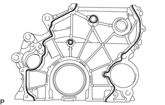
Apply seal packing in a continuous line as shown in the illustration.
- Standard seal diameter:
1.5 to 2.0 mm (0.0591 to 0.0787 in.)
- NOTICE:
- ·
Remove any oil from the contact surface.
·Install the timing chain cover plate within 3 minutes of applying seal packing.
·Do not start the engine for at least 4 hours after installation.
Using an E8 "TORX" socket wrench, install the timing chain cover plate with the 11 bolts.
- Torque:
- : 20 N*m (204 kgf*cm, 15 ft.*lbf)
Apply a light coat of engine oil to a new O-ring, and install it to the sealing cap.
Install the sealing cap to the timing case housing.
- Torque:
- : 20 N*m (204 kgf*cm, 15 ft.*lbf)
11401L
10.INSTALL REAR ENGINE OIL SEAL
15100
11.INSTALL OIL PUMP WITH VACUUM PUMP ASSEMBLY
15104
12.INSTALL OIL STRAINER SUB-ASSEMBLY
12101
13.INSTALL OIL PAN SUB-ASSEMBLY
14.INSTALL FLYWHEEL WITH DAMPER ASSEMBLY
31250
15.INSTALL CLUTCH DISC ASSEMBLY
31210
16.INSTALL CLUTCH COVER ASSEMBLY
31210
17.INSPECT AND ADJUST CLUTCH COVER ASSEMBLY
11301C
18.INSTALL TIMING GEAR CASE OR TIMING CHAIN CASE OIL SEAL
13471
19.INSTALL CRANKSHAFT PULLEY
11115
20.SELECT CYLINDER HEAD GASKET
11115
21.INSTALL CYLINDER HEAD GASKET
11101
22.INSTALL CYLINDER HEAD SUB-ASSEMBLY
13750
23.INSPECT VALVE LASH ADJUSTER ASSEMBLY
13750
24.INSTALL VALVE LASH ADJUSTER ASSEMBLY
13801
25.INSTALL NO. 1 VALVE ROCKER ARM SUB-ASSEMBLY
11103
26.INSTALL CAMSHAFT HOUSING SUB-ASSEMBLY
27.SET NO. 1 CYLINDER TO TDC/COMPRESSION
13511
28.INSTALL CAMSHAFT AND NO. 2 CAMSHAFT
11201
29.INSTALL CYLINDER HEAD COVER SUB-ASSEMBLY
12108
30.INSTALL OIL FILLER CAP SUB-ASSEMBLY
Install the oil filler cap sub-assembly to the cylinder head cover sub-assembly.
15600
31.INSTALL OIL FILTER ASSEMBLY
15601
32.INSTALL OIL FILTER SUB-ASSEMBLY
16331
33.INSTALL WATER OUTLET
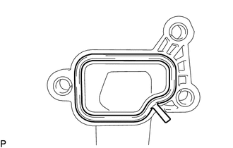
Install a new gasket to the water outlet.
Using an E10 "TORX" socket wrench, install the water outlet with the 3 bolts.
- Torque:
- : 10 N*m (102 kgf*cm, 7 ft.*lbf)
16323
34.INSTALL WATER INLET HOUSING
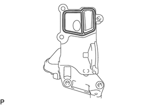
Apply seal packing in a continuous line as shown in the illustration.
- Standard seal diameter:
2.0 to 2.5 mm (0.0787 to 0.0984 in.)
- NOTICE:
- ·
Remove any oil from the contact surface.
·Install the water inlet housing within 3 minutes of applying seal packing.
·Do not start the engine for at least 4 hours after installation.
Using an E11 "TORX" socket wrench, install the water inlet housing with the 5 bolts.
- Torque:
- : 20 N*m (204 kgf*cm, 15 ft.*lbf)
16331A
35.INSTALL THERMOSTAT
16321
36.INSTALL WATER INLET
16268L
37.INSTALL WATER BY-PASS PIPE
Using a 5 mm hexagon socket wrench, install the water by-pass pipe to the water inlet housing with the bolt.
- HINT:
-
Refer to "SPECIFICATIONS - STANDARD BOLT" for the tightening torque.
16100
38.INSTALL ENGINE WATER PUMP ASSEMBLY
23670
39.INSTALL INJECTOR ASSEMBLY
23760
40.INSTALL NOZZLE LEAKAGE PIPE ASSEMBLY
83530
41.INSTALL ENGINE OIL PRESSURE SWITCH ASSEMBLY
89422C
42.INSTALL ENGINE COOLANT TEMPERATURE SENSOR
43.INSTALL CRANKSHAFT POSITION SENSOR
44.INSTALL CAMSHAFT POSITION SENSOR