B58 ENGINE MECHANICAL PISTON REMOVAL
PROCEDURE

 1.REMOVE ENGINE ASSEMBLY
2.REMOVE SPARK PLUG
17882
3.REMOVE NO. 2 AIR CLEANER HOSE
15620
4.REMOVE OIL FILTER CAP ASSEMBLY
12101A
5.REMOVE OIL PAN DRAIN PLUG
12101A
6.INSTALL OIL PAN DRAIN PLUG
15620
7.INSTALL OIL FILTER CAP ASSEMBLY
23801P
8.REMOVE NO. 1 FUEL PIPE SUB-ASSEMBLY
23100X
9.REMOVE FUEL (ENGINE ROOM SIDE) PUMP ASSEMBLY
23250
10.REMOVE FUEL INJECTOR ASSEMBLY (for Front Side)
23250
11.REMOVE FUEL INJECTOR ASSEMBLY (for Rear Side)
15370J
12.REMOVE CAM TIMING OIL CONTROL SOLENOID ASSEMBLY
11201
13.REMOVE CYLINDER HEAD COVER SUB-ASSEMBLY
17111
14.REMOVE INTAKE MANIFOLD
15474
15.REMOVE OUTLET TURBO OIL PIPE
17293
16.REMOVE TURBOCHARGER STAY
17.SET NO. 1 CYLINDER TO TDC (COMPRESSION)
13540
18.REMOVE NO. 1 CHAIN TENSIONER ASSEMBLY
135A0
19.LOOSEN RELEASING INTAKE CAMSHAFT TIMING GEAR BOLT ASSEMBLY
135A0A
20.LOOSEN EXHAUST CAMSHAFT TIMING GEAR BOLT ASSEMBLY
135A0
21.REMOVE INTAKE CAMSHAFT TIMING GEAR BOLT ASSEMBLY
135A0A
22.REMOVE EXHAUST CAMSHAFT TIMING GEAR BOLT ASSEMBLY
13050
23.REMOVE CAMSHAFT TIMING GEAR ASSEMBLY
13070A
24.REMOVE CAMSHAFT TIMING EXHAUST GEAR ASSEMBLY
25.REMOVE SST
11101
26.REMOVE CYLINDER HEAD SUB-ASSEMBLY
11115
27.REMOVE CYLINDER HEAD GASKET
12101
28.REMOVE OIL PAN SUB-ASSEMBLY
15100
29.REMOVE OIL PUMP ASSEMBLY
12121
30.REMOVE NO. 1 OIL PAN BAFFLE PLATE
13201
31.REMOVE CONNECTING ROD SUB-ASSEMBLY
- NOTICE:
- ·
Damage on the cylinder wall and oil spray nozzles.
Major force can scratch the cylinder wall and bend the oil spray nozzles.
-Carefully move the piston and connecting rod sub-assembly in the engine block.
·Piston, gudgeon pin, connecting rod sub-assembly and connecting rod bearings are matched to each other and balanced.
Always install the piston, gudgeon pin, connecting rod and connecting rod bearing shells in the cylinder from which they were removed.
·The connecting rod sub-assemblies of the engine are balanced and are matched to each other.
A single connecting rod sub-assembly is not permitted to be replaced. Always replace all connecting rod sub-assemblies.
- HINT:
-
The description is for one component only. The procedure is identical for all further components.
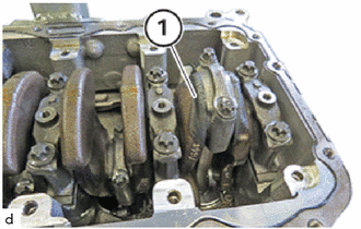
Turn the crankshaft until the connecting rod bearing journal (1) reaches a vertical position.
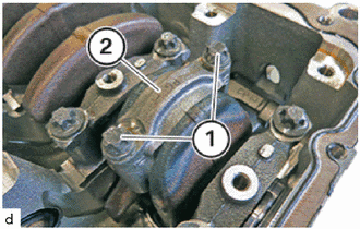
Loosen E12 bolts (1).
- NOTICE:
- ·
Engine damage caused by incorrectly installed connecting rod bearings and connecting rod bearing caps.
Engine damage may result from incorrectly installing connecting rod bearings and connecting rod bearing caps.
-Always install all connecting rod bearings and connecting rod bearing caps in the same position from which they were removed.
Remove the connecting rod bearing cap (2) and put to one side in the correct order.
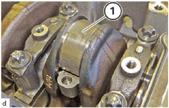
Remove connecting rod bearing (1).
- NOTICE:
- ·
Engine damage caused by incorrectly installed connecting rod bearings and connecting rod bearing caps.
Engine damage may result from incorrectly installing connecting rod bearings and connecting rod bearing caps.
-Always install all connecting rod bearings and connecting rod bearing caps in the same position from which they were removed.
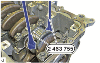
Bolt special tool 2 463 755 in at large connecting rod eye.
- SST
- 09200-WA730
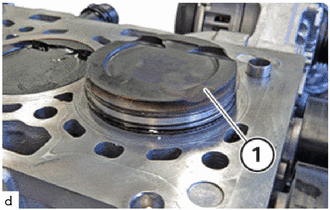
Push the piston (1) and the connecting rod upwards out of the crankcase.
32.INSPECT PISTON
- HINT:
-
The description is for one component only. The procedure is identical for all further components.
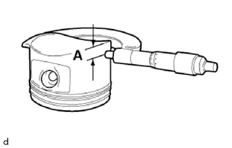
Position measuring bolt in area (A) and measure piston installation clearance transversely to gudgeon pin.
- Piston diameter:
Distance (A) to the lower end of the piston skirt Nominal dimension of piston diameter 14 mm (0.551 in.) 81.938 to 81.956 mm (3.226 to 3.227 in.) 26 mm (1.02 in.) 81.870 to 81.884 mm (3.223 to 3.224 in.) 49 mm (1.93 in.) 81.285 to 81.309 mm (3.200 to 3.201 in.)
- HINT:
-
If the piston diameter is not as specified, replace the piston.
33.REMOVE PISTON PIN HOLE SNAP RING
- NOTICE:
-
The description is for one component only. The procedure is identical for all further components.
- HINT:
-
Wear safety goggles.
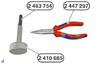
Use special tools 2 463 754 , 2 410 685 and 2 447 297 to remove the piston from the connecting rod sub-assembly.
- SST
- 09200-WA580
09200-WA750
09900-WA150
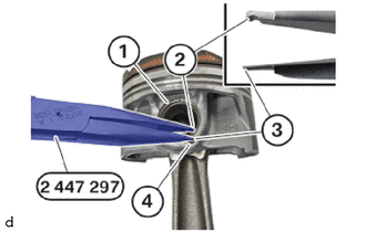
Use special tool 2 447 297 to remove the piston pin hole snap ring.
- SST
- 09900-WA150
- CAUTION:
- ·
Spring preload.
Danger of injury!
-The use of the specified special tool for the disassembly or installation is mandatory.
-Wear safety goggles.
Insert the flat side (3) of the special tool into the groove (4).
Remove piston pin hole snap ring (1).
- HINT:
-
Piston and piston pin are matched to each other.
-
Always install piston and piston pin together and do not switch by mistake.
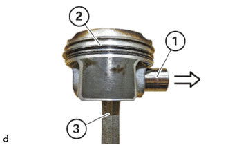
Check whether the piston pin (1) demonstrates tangible play in the piston.
Check whether the piston pin (1) can be removed without excessive force.
Removing the piston pin (1) is very difficult, or piston pin (1) has noticeable play.
Replace the piston (2) and the Piston pin (1).
34.REMOVE PISTON RING
- CAUTION:
- ·
Very wide spreading of the piston rings during installation / removal.
·Damage to the piston rings.
-Spread the piston rings only until the piston ring can just be slid over the piston.
-Use piston ring pliers to install and remove the piston rings.
·Wear safety goggles.
- NOTICE:
-
The description is for one component only. The procedure is identical for all further components.
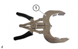
Keep the standard piston ring pliers (1) ready.
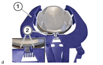
Position the piston ring pliers (1) on the top piston ring (2).
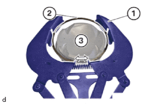
Tension the piston ring pliers (1) in the direction of arrow, feed out and remove the top piston ring (2).
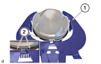
Position the piston ring pliers (1) on the middle piston ring (2).
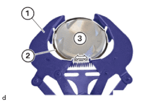
Tension the piston ring pliers (1) in the direction of arrow, feed out and remove the top piston ring (2).
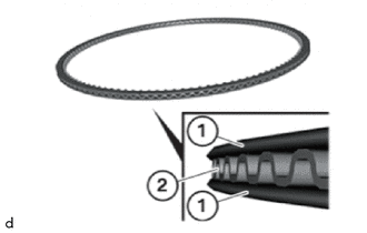
Remove the oil scraper ring (1) and the spring (2) by hand.
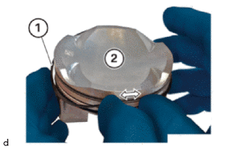
Feed out both oil scraper rings (1) in the direction of arrow on the piston (2) and remove.
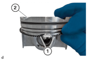
Feed out and remove the spring (1) in the direction of arrow on the piston (2).
35.INSPECT PISTON RING END GAP
- NOTICE:
-
Schematic diagram is for example purposes. Some parts may differ in certain details.
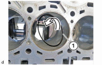
Place new piston rings (1) into the cylinder to be measured and turn through 90° in direction of the arrow.
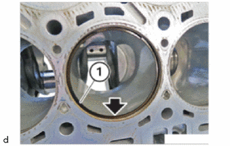
Position all new piston rings (1) in succession in the cylinder barrel below the top dead centre (arrow).
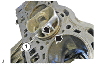
Press in all new piston rings in succession with the help of the piston (1) up to the last annular groove (arrows) in parallel.
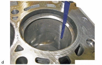
In succession, measure the end clearance of all piston rings as shown with a feeler gauge.
- Standard End Gap:
End Gap, top (plain rectangular compression ring) End Gap, middle (taperfaced pistonring) 0.2 to 0.3 mm (0.0079 to 0.0118 in.) 0.2 to 0.3 mm (0.0079 to 0.0118 in.)
- HINT:
- ·
The End Gap of the piston rings is outside of the tolerance.
-Check cylinder for wear; measure the cylinder if necessary.
36.INSPECT RING GROOVE CLEARANCE
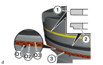
Observe the arrangement of the piston rings:
Upper piston ring (1): Plain rectangular compression ring (engraving must point upwards)
Centre piston ring (2): Taper faced piston ring (engraving must point upwards)
Oil scraper ring (3): Consisting of 2 piston rings (O1) and (O3) with a spring (O2) in the centre
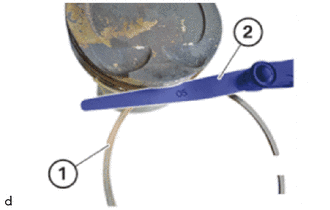
With a feeler gauge, measure the side clearance of the new upper piston ring (plain rectangular compression ring).
- Standard Ring Groove Clearance:
Ring groove clearance of the piston ring, middle 0.035 to 0.85 mm (0.0014 to 0.0335 in.)
- HINT:
- ·
The clearance is outside of the tolerance.
-Renew the piston.
With a feeler gauge, measure the side clearance of the newcentre piston ring (taper faced piston ring).
- Standard Ring Groove Clearance:
Ring groove clearance of the piston ring, middle 0.015 to 0.06 mm (0.0006 to 0.0024 in.)
- HINT:
- ·
The clearance is outside of the tolerance.
-Renew the piston.